


CM3 GYM SYSTEM
WARNING:
Read and follow all directions for each step to insure proper assembly of this product.
USER’S GUIDE
CLASS H |
1 |
Version: CM3-105 |
PART # 7657801 |
|
Revision: 09/01/05 |
REV.A |
|
|

TABLE OF CONTENTS
Safety Statement |
.............2 |
General Notes.................. |
3 |
Tools Required................ |
3 |
Gym Layout................... |
4 |
Parts list ........................ |
5 |
Cabling Diagrams........... |
6-10 |
Assembly Instructions.... |
10-28 |
General Maintenance....... |
29 |
Warranty Statement......... |
30 |
Product Services............. |
31 |
Insert-Registration Card |
|
IMPORTANT SAFETY INFORMATION
THERE IS A RISK ASSUMED BY INDIVIDUALS WHO USE THIS TYPE OF
EQUIPMENT. TO MINIMIZE RISK FOLLOW THESE RULES!
1.Before using, read all the warnings and instructions on the use of this machine. Use only for intended exercise. DO NOT modify the machine.
2.Obtain a medical exam before beginning any exercise program.
3.Keep body and clothing free of all moving objects.
4.Inspect the machine before use. DO NOT use it if it appears damaged. DO NOT attempt to fix a broken or
jammed machine. Notify your authorized ParaBody dealer before use and have repairs made by an authorized service technician.
5. Be certain that weight pin is completely inserted. Use only the pin provided by the manufacturer. If unsure, call your authorized ParaBody dealer.
6. Never pin the weights or prop plate into an elevated position. DO NOT use the machine if found in this condition. DO NOT attempt to fix. Notify your authorized ParaBody dealer.
7. Inspect cables and their connections before using machine. Pay particular attention to the cable ends. DO NOT attempt to fix. Notify your authorized ParaBody dealer before use and have repairs made by an authorized service technician.
8.Make sure all spring loaded pull pins are fully engaged in the adjustment position and fully tighten thumbscrew before use.
9.Children must not be allowed near this machine. Supervise teenagers.
.
NOTE: In a continual effort to improve our products, specifications are subject to change © 2005 Life Fitness, a division of Brunswick Corporation. All rights reserved. ParaBody is a trademark of Brunswick Corporation
www.parabody.com
2
IMPORTANT NOTES
Please note:
*Thank you for purchasing the ParaBody CM3 Gym System. Please read these instructions thoroughly and keep them for future reference.
*This product must be assembled on a flat, level surface to assure its proper function.
*Do not securely tighten any frame connections until the entire frame have been assembled unless otherwise specified.
Tools Required for Assembly
*Rubber mallet or hammer
*3/4” wrench
*9/16” wrench
*Ratchet with 3/4” and 9/16” sockets
*5/32” Allen wrench
*Adjustable wrench
*Tape measure
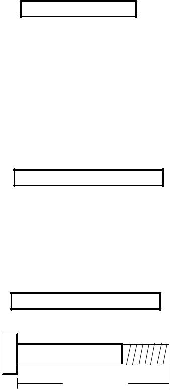
Bolt Length Ruler
NOTE: BOLT LENGTH IS MEASURED FROM THE UNDERSIDE OF THE HEAD OFTHE BOLT.
BOLT LENGTH
BOLT LENGTH RULER:
|
1/2 |
|
1/2 |
|
1/2 |
|
1/2 |
|
1/2 |
|
|
1/2 |
|
|||||||||||
0 |
|
|
1 |
|
|
2 |
|
|
3 |
|
|
4 |
|
|
5 |
|
6 |
|||||||
|
|
|
|
|
|
|
|
|
|
|
|
|
|
|
|
|
|
|
|
|
|
|
|
|
3
1’ |
2’ |
3’ |
4’ |
5’ |
6’ |
7’ |
8’ |
9’ |
1’
2’
3’
4’
5’
6’
7’
8’
9’
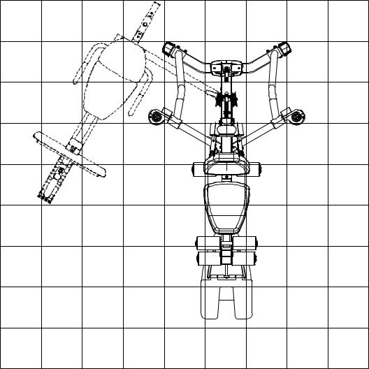
1 Square = 1’ X 1’
Minimum Required Usable Space
Length |
= 90 inches (229 cm) 7’ 6” |
Width |
= 103 inches (262 cm) 8’ 7” |
Height |
= 84 inches (213.5 cm) 7” |
Dimensions Including LP5 Leg Press (optional)
Length |
= 102 inches (259 cm) 8’ 6” |
Width |
= 130 inches (330 cm) 10’ 10” |
4

PARTS LIST
KEY |
PART # |
DESCRIPTION |
QTY |
1 |
ACU04-0906 |
FRONT BASE |
1 |
2 |
ACU04-0909 |
UPRIGHT |
1 |
3 |
ACU04-0907 |
BASECONNECTOR |
1 |
4 |
ACU04-0908 |
REAR BASE |
1 |
5 |
ACU04-0902 |
RIGHTARM |
1 |
6 |
ACU04-0903 |
LEFTARM |
1 |
7 |
ACU04-1162 |
SEATADJUST |
1 |
8 |
ACU04-1157 |
LEGPEDESTAL |
1 |
9 |
ACU04-1172 |
PULLEYBRACKET |
1 |
10 |
ACU02-1071 |
PULLEYPLATE |
2 |
11 |
ACU02-1093 |
BASE PLATE |
2 |
12 |
ACU05-0295 |
C-RING |
2 |
13 |
ACU02-1092 |
BOOMPULLEYPLATE |
2 |
14 |
ACU04-0905 |
RIGHT BOOM PLATE |
1 |
15 |
ACU04-0904 |
LEFTBOOM PLATE |
1 |
16 |
ACU07-0100 |
SEAT/BACK PAD |
2 |
17 |
ACU06-0337 |
ROLLERPAD |
6 |
18 |
ACU01-2155 |
76”GUIDEROD |
2 |
19 |
ACU12-0067 |
ADJUST. SEWN HANDLE |
2 |
20 |
ACU12-0068 |
SHORTSEWN HANDLE |
2 |
21 |
ACU7292501 |
WEIGHT PLATE |
15 |
22 |
ACU04-0622 |
LOW ROW BAR |
1 |
23 |
ACU10-0204ASY |
HEAD PLATEASSY |
1 |
24 |
ACU04-0932A |
3/4 X 18” TUBE |
1 |
25 |
ACU04-0934A |
3/4 X 18-3/8” TUBE |
1 |
26 |
ACU04-0935 |
3/4 X 21” TUBE |
1 |
27 |
ACU11-0060 |
WEIGHT STACK PIN |
1 |
28 |
ACU06-0034 |
WEIGHT STACK CUSHION |
2 |
29 |
ACU13-0112-2 |
WEIGHTSTACK CABLE |
1 |
30 |
ACU13-0112-4 |
LEGCABLE |
1 |
31 |
ACU13-0112-5 |
ARM CABLE |
1 |
32 |
ACU13-0112-1 |
BOOM CABLE |
1 |
33 |
ACU04-1165 |
WEIGHTSTACK SPACER |
2 |
34 |
ACU04-1171 |
3-1/2 CABLE GUARD |
1 |
35 |
ACU04-1342 |
4-1/2 CABLE GUARD |
1 |
36 |
ACU05-0212 |
SHAFT COLLAR |
2 |
KEY |
PART # |
DESCRIPTION |
QTY |
37 |
ACU06-0051 |
3-1/2”PULLEY |
18 |
38 |
ACU06-0035 |
4-1/2”PULLEY |
3 |
39 |
ACUKN000097 |
QUICKCONNECT |
4 |
40 |
ACU11-0068 |
T-HANDLE SPRING PIN |
1 |
41 |
ACUDI1080080U |
SNAP LINK |
4 |
42 |
ACU04-1343 |
GUIDEBRACKET |
1 |
43 |
ACU06-0194 |
3PRONGKNOB |
1 |
44 |
ACU05-0277 |
ROLLER PAD CAP |
6 |
45 |
ACU06-0363 |
PLASTIC WASHER |
12 |
46 |
ACU05-0146 |
1/2” RH WASHER |
2 |
47 |
ACU06-0021 |
RH CAP |
2 |
48 |
ACU08-0074 |
3/8” X 3/4” FLANGE SPACER |
2 |
49 |
ACU08-0066 |
3/8 X 1-1/16” FLANGE SPACER |
2 |
50 |
ACU05-0300 |
ACCESSORYRING |
2 |
51 |
ACU03-0042 |
3/8” X 1” SPACER |
9 |
52 |
ACUMD000059 |
WEIGHT STACK LABEL |
1 |
53 |
ACUDA1E03813416NB |
3/8 X 1-3/4” BOLT |
10 |
54 |
ACUDAEE51610018YB |
5/16 x 1” BUTTON HEAD |
6 |
55 |
ACUDA1E03820016NB |
3/8 X 2” BOLT |
2 |
56 |
ACU06-0358 |
2” NYLON SPACER |
4 |
57 |
ACUDA1E03833416NB |
3/8 X 3-3/4” BOLT |
20 |
58 |
ACUDA1C01210413NB |
1/2 X 104mm BOLT |
1 |
59 |
ACU05-0030 |
12 LINK CHAIN |
1 |
60 |
ACUDA1E03823416NB |
3/8 X 2-3/4” BOLT |
2 |
61 |
ACUDA1C01253413NB |
1/2 X 5-3/4” BOLT |
1 |
62 |
ACUDB2E01208000B |
1/2” LOW HEIGHT LOCK NUT |
2 |
63 |
ACUDB2E03811000B |
3/8” LOCK NUT |
40 |
64 |
ACUDC1250100020B |
3/8” FLAT WASHER |
18 |
65 |
ACU13-0112-3 |
GUIDECABLE |
2 |
66 |
ACU04-1100 |
FOOT PLATE |
1 |
67 |
ACUDA1E03830016NB |
3/8 X 3” BOLT |
4 |
68 |
ACUDA1E03841416NB |
3/8 X 4-1/4” BOLT |
4 |
70 |
ACUDA1E03811416NB |
3/8 X 1-1/4” BOLT |
2 |
71 |
AP04-0910 |
BACK PADADJUSTMENT |
1 |
72 |
P04-0911 |
SWIVELPULLEYASSEMBLY |
2 |
73 |
ACU12-0041 |
ANKLE STRAP |
1 |
NOTE: SOMEOFTHEPARTSLISTEDMAYBEPRE-INSTALLED.
|
1/2 |
|
1/2 |
|
1/2 |
|
1/2 |
|
1/2 |
|
|
1/2 |
|
|||||||||||
0 |
|
|
1 |
|
|
2 |
|
|
3 |
|
|
4 |
|
|
5 |
|
6 |
|||||||
|
|
|
|
|
|
|
|
|
|
|
|
|
|
|
|
|
|
|
|
|
|
|
|
|
5
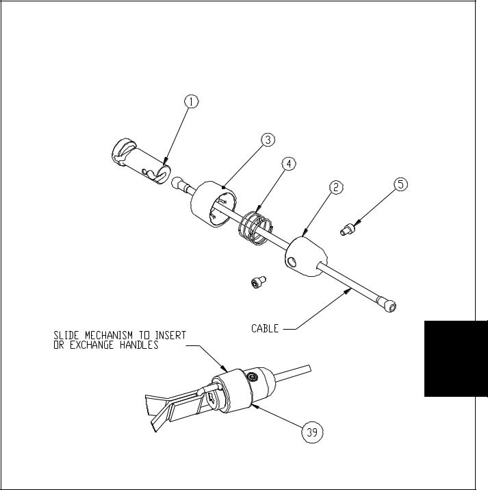
ITEM |
QTY. |
PART NO. |
DESCRIPTION |
1 |
1 |
7726201 |
COUPLER, QUICK CONNECT |
2 |
1 |
7726401 |
HSNG, QUICK CONNECT |
3 |
1 |
7726301 |
SLEEVE, QUICK CONNECT |
4 |
1 |
3249901 |
SPRING, COMPRESSION |
5 |
2 |
3250002 |
M5 X 0.8 HXS SOC CS ST BZ X 8 |
DIAGRAM 1 |
• |
Slide each item onto the cable as follows: ITEM 2, ITEM 4, ITEM 3, and insert cable end into ITEM 1. |
• |
Slide entire assembly over ITEM 1 and secure by screwing ITEM 5 both sides into ITEM 4 and TIGHTEN. |
6
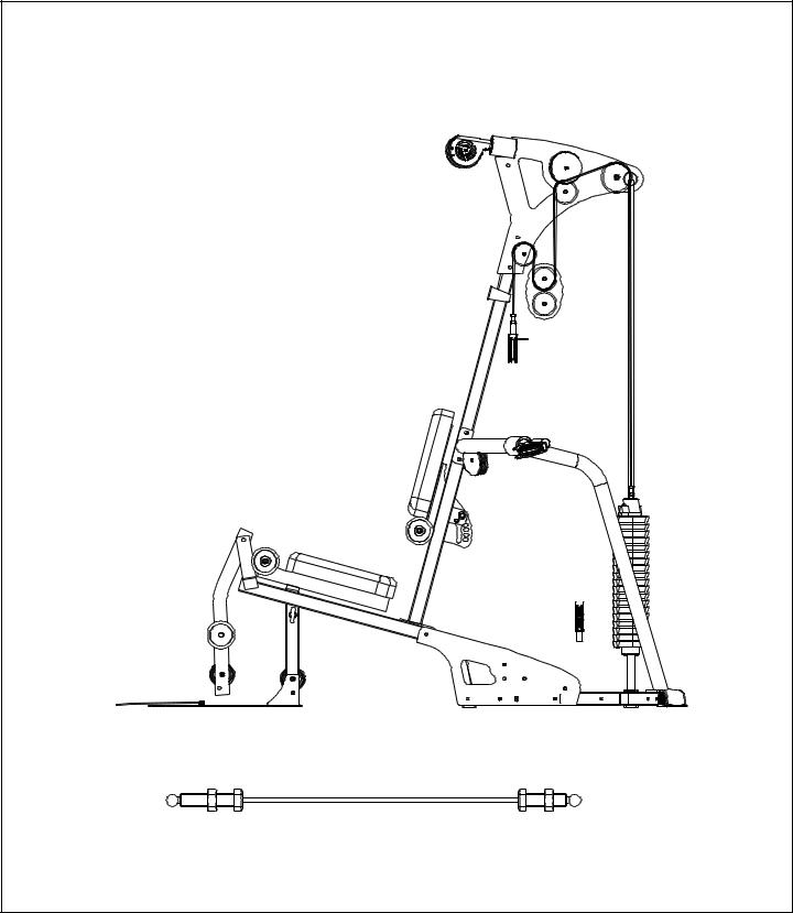
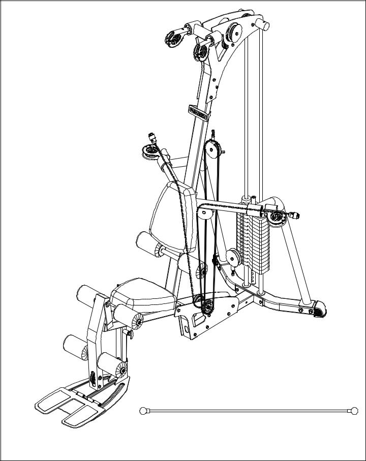
P13-0112-2 DIAGRAM 2
7

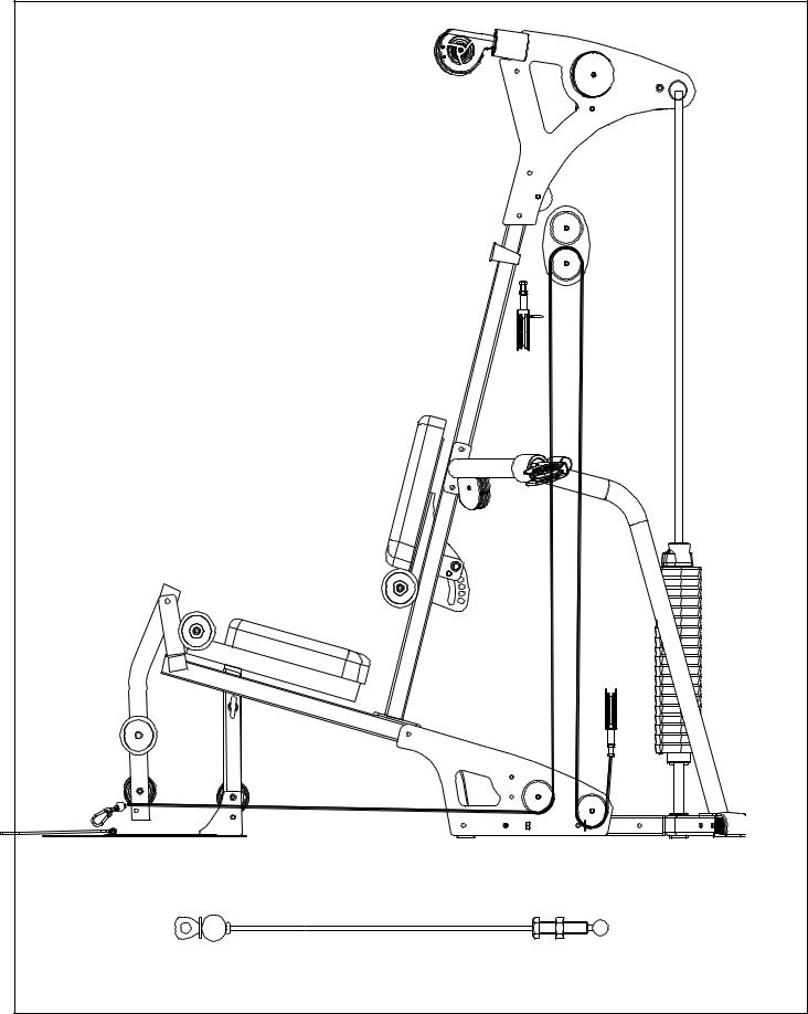
P13-0112-1 |
DIAGRAM 3 |
8 |
P13-0112-5 |
DIAGRAM 4 |
9 |
P13-0112-4 |
DIAGRAM 5 |
10 |
 Loading...