


Leg Press Factor 625
9/t~ inch wrench
~ odiustable wrench
inch wrench
¯ hammer or rubber mallet
inch wrench
¯ s~2 allen wrench
¯ THE PARABODY FACTOR 625 BASE UNIT MUST BE ASSEMBLED ON A FLAT, LEVEL SURFACE TO ASSURE ITS PROPER FUNC1
¯ PARABODY STRONGLY RECOMMENDS THAT THIS PRODUCT BE ASSEMBLED BY TWO PERSONS TO AVOID POSSIBLE INJURY.
,, KEEP ALL FRAME BOLT CONNECTIONS LOOSE UNTIL INSTRUCTED IN THE ASSEMBLY STEP SEQUENCES TO SECURELY TIGHTi
MAKE SURE SNAP HOOKS ARE FASTENED BEFORE DOING EXERCISES.
NOTE:We recommend cleaning your produd (pads and the frame members
PoraBody Customer Service Representative at 1-800-328-9714.
on a regular basis, using worm soapy water. Also, touch-up paint can be purchnsed from your
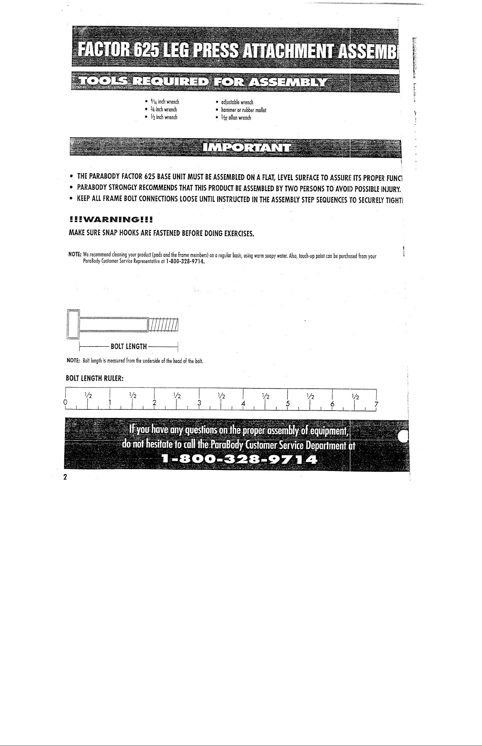
BOLT LENGTH
NOTE: Bolt length ismensured from the underside of the head of the bolt.
BOLT LENGTH RULER:
TTS/PARTS:
OTY.
NAME/DESCRIPTION
~
~(P~78-011
1
Back Pod
~--~B0-01 )
1
Leg Press Frame
~PB3170-01)
1
Telescoping Tube Plated ~"-’~43-01)
l
~~- -- (PB3047-01)
1
Pivot Axle __
[PB3OBI-01)
1
(PB3236-01)
l
Leg Press Cable 17
’~
~634-01)
4
Non-Skid Strip 4" x
count all parts before beginning assembly.
’ARE:
NAME/DESCRIPTION
QTY.
-
’
Gr---’-~p I I/4
"
x S"
2
~/4" x I" Oilite Bushing
-- I
~Compressi.___~on Spr~
l
Co~e~ Pin
l
P~unger
Spacer
Knob
~" Square E.nd_ Cop (I 0-I 4 ga)~
Weight Stock Bumper
3/B" x l lh
’’
Bol~ ’t
-~e" Washer
~osher
~ Washer
~Pulley
3/~" x 4~/~
"
Bol~
1
l
l
5
7
2
2
4
1
3
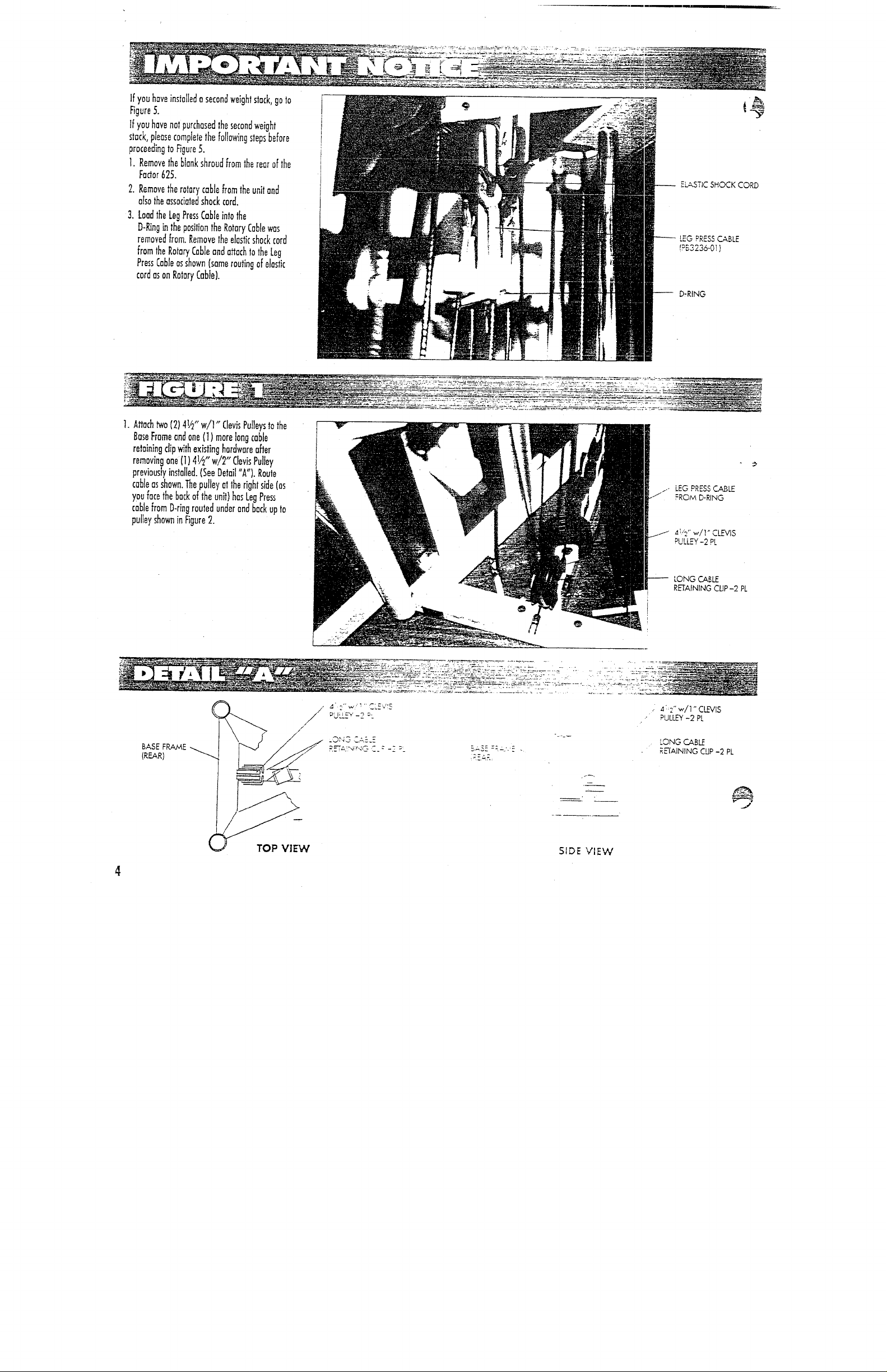
If you have installed a second weight stack, go to
Figure 5.
If you have not purchased the second weight
stack, please camp]ere the folJowing steps before
proceeding to F~gure 5.
1.Remove the blank shroud from the rear of the
Factor 625.
2.Remove the rotary cable from the unit and
also the assadated shock cord.
3.Load the Leg Press Cable into the
D-Ring in the position the Rotary Cable was
removed from. Remove the elastic shock cord
from the Rotary Cable and attach to the Leg
Press Cable as shown (same routing of elastic
cord as on Rotary Cable).
ELASTIC SHOCK CORD
LEG PRESS CABLE
(PB3236-01)
-- D:RING
1. Attach two (2) 4V2 w/l Clev;s Pulleys to the
t
’~ ’--:~ ~ --~’-
Base Frame and one {I) mare long cable
retaining clip with existing hardware after
removing one (1) 41/2" w/2" Clevis Pulley
previously installed. (See Detail "A"). Route
~
cable as shown. The pulley at the right side (as ~k~.
LEG PRESS C.ABLE
you face the back of the unit) has Leg Press
FRO,~ D-RING
cable from D-ring routed under and back up to
pulley shown in Figure 2.
PULLEY-2 PL
LONG
R~AINING CUP-2 PL
. PULL~ -2 PL
SIDE VIEW
 Loading...