

Page 1
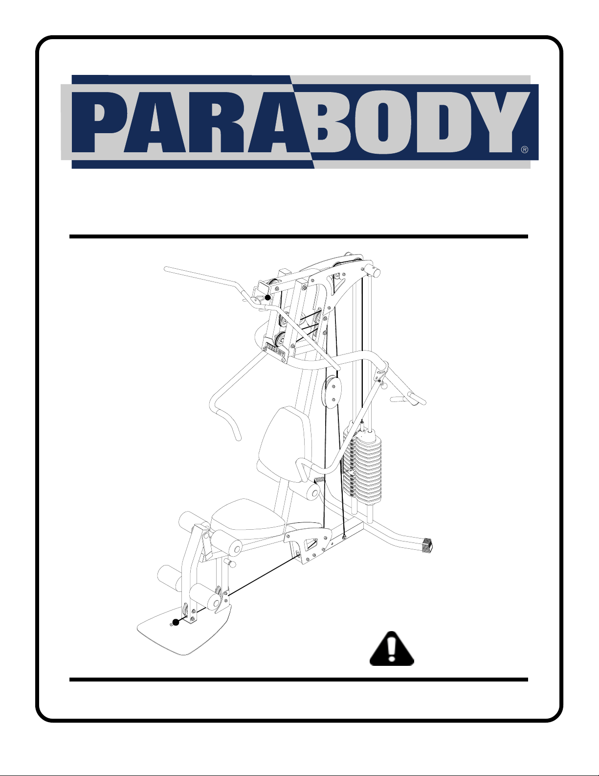
220 GYM SYSTEM
CLASS H
PART # 7017301
REV . G
USER’S GUIDE
1
WARNING:
Read and follow all directions
for each step to insure proper
assembly of this product.
Version: 220101
Revision: 09/13/01
Page 2
j
TABLE OF CONTENTS
Safety Statement.............2
General Notes..................3
Tools Required................3
Gym Layout.....................4
Parts list..........................5
Assembly Instructions.....6-21
General Maintenance.......22
W arranty Statement..........23
Product Services..............24
Insert-Registration Card
IMPORTANT SAFETY INFORMATION
THERE IS A RISK ASSUMED BY INDIVIDUALS WHO USE THIS TYPE OF
EQUIPMENT. TO MINIMIZE RISK FOLLOW THESE RULES!
1. Before using, read all the warnings and instructions
on the use of this machine. Use only for intended
exercise. DO NOT modify the machine.
2. Obtain a medical exam before beginning any
exercise program.
3. Keep body and clothing free of all moving objects.
4. Inspect the machine before use. DO NOT use it if it
appears damaged. DO NOT attempt to fix a broken or
ammed machine. Notify your authorized ParaBody
dealer before use and have repairs made by an
authorized service technician.
6. Never pin the weights or prop plate into an elevated
position. DO NOT use the machine if found in this
condition. DO NOT attempt to fix. Notify your
authorized ParaBody dealer.
7. Inspect cables and their connections before using
machine. Pay particular attention to the cable ends.
DO NOT attempt to fix. Notify your authorized
ParaBody dealer before use and have repairs made by
an authorized service technician.
8. Make sure all spring loaded pull pins are fully
engaged in the adjustment position and fully tighten
thumbscrew before use.
5. Be certain that weight pin is completely inserted.
Use only the pin provided by the manufacturer. If
unsure, call your authorized ParaBody dealer.
9. Children must not be allowed near this machine.
Supervise teenagers.
.
NOTE: In a continual effort to improve our products, specifications are subject to change
2001 Life Fitness, a division of Brunswick Corporation. All rights reserved.
©
ParaBody is a trademark of Brunswick Corporation
www.parabody.com
2
Page 3
IMPORTANT NOTES
Please note:
* Thank you for purchasing the ParaBody 220 Gym System. Please read these
instructions thoroughly and keep them for future reference.
* This product must be assembled on a flat, level surface to assure its proper function. DO NOT
securely tighten any frame connections until the entire frame has been assembled, unless
otherwise stated.
T ools Required for Assembly
* Rubber mallet or hammer
* 3/4” wrench
* 9/16” wrench
* Ratchet with 3/4” and 9/16” sockets
* 5/32” Allen wrench
* Adjustable wrench
* T ape measure
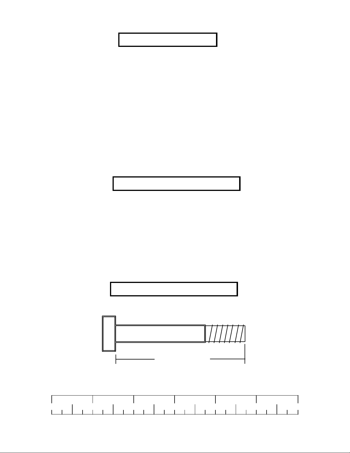
Bolt Length Ruler
NOTE: BOL T LENGTH IS MEASURED FROM THE UNDERSIDE OF THE HEAD OF THE BOLT.
BOLT LENGTH
BOL T LENGTH RULER:
1/2 1/2 1/2 1/2 1/2 1/2
0
1
2
345
3
6
Page 4
1’
2’
3’
4’
5’
4’
5’
6’
7’ 8’
9’1’ 2’ 3’
6’
7’
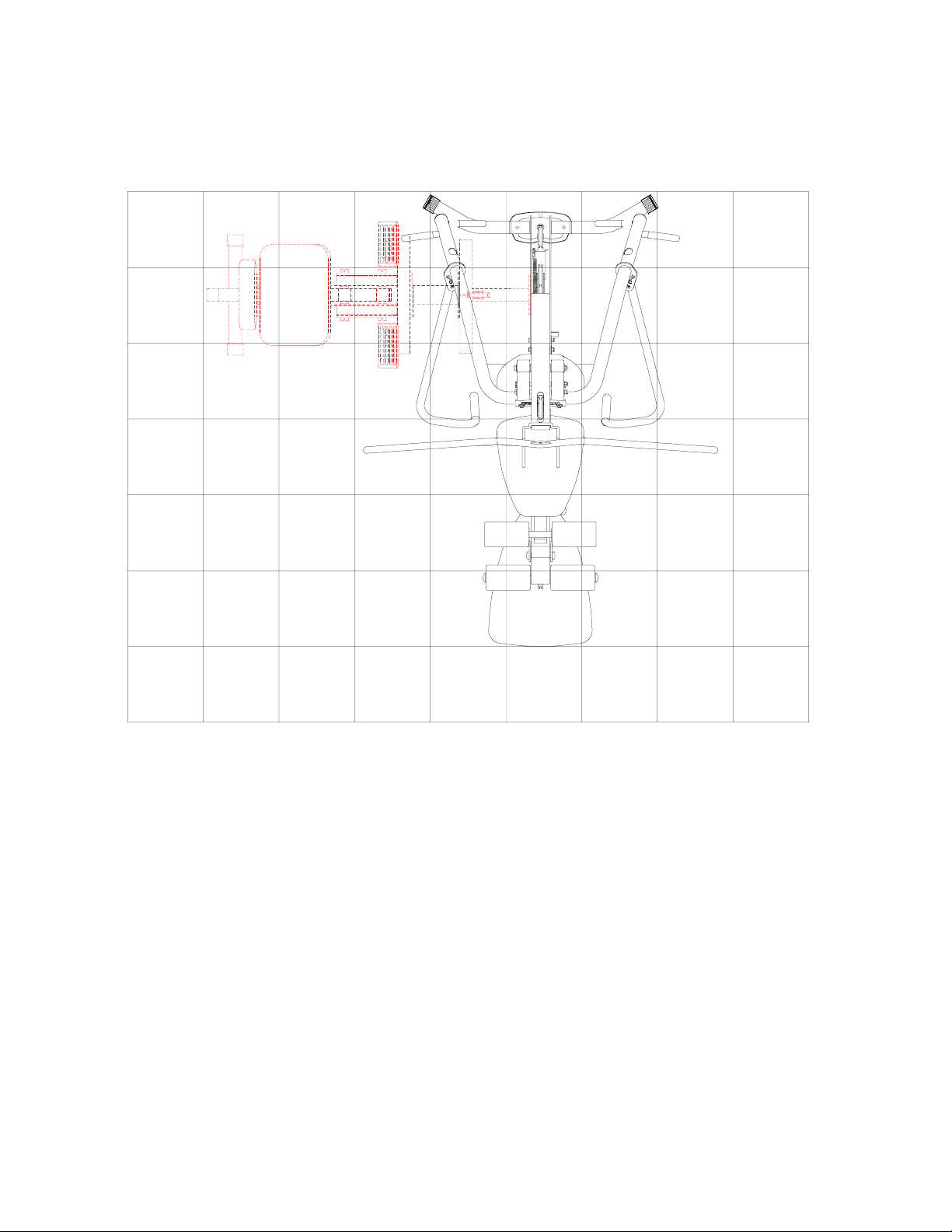
1 Square = 1’ X 1’
Minimum Required Usable Space
Length = 82 inches (208.5 cm) 6’ 10”
Width = 71 inches (180.5 cm) 5’11”
Height = 83 inches (211 cm) 6’ 11”
Dimensions Including Leg Press (optional)
Length = 82 inches (208.5 cm) 6’ 10”
Width = 108 inches (180.5 cm) 9’ 0”
4
Page 5
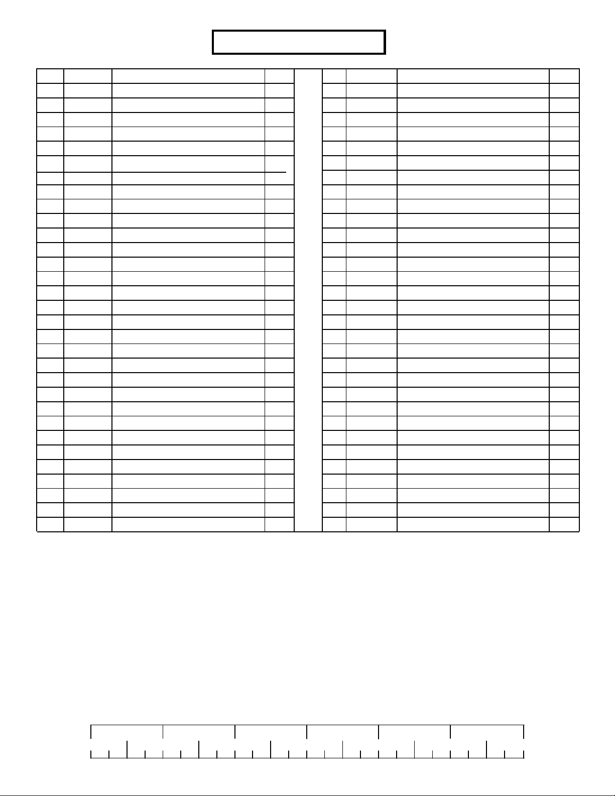
PARTS LIST
KEY
1
2
3
4
5
6
7
8
9
10
11
12
13
14
15
16
17
18
19
20
21
22
23
24
25
26
27
28
29
30
PART #
7005008
7005708
6994608
7005308
7005208
7005408
7005508
6999708
7005108
7005808
7005608
6940808
6994721
6549301
6194601
6523401
7006202
7015701
6953702
7014101
7014201
6939202
6382301
3116201
6409101
6075906
3102924
3102922
3102904
3102905
DESCRIPTION
FRAME
BASE
BASE PLA TE
BOOM PLA TE LEFT
BOOM PLA TE RIGHT
PRESS HANDLE RIGHT
PRESS HANDLE LEFT
PRESS ARM
PRIMARY PIVOT
SEA T ADJUST
LEG PEDEST AL
PULLEY PLATE
SEA T P AD
3/4 X 17” TUBE
4 X 7” ROLLER PAD
72-3/8” GUIDE ROD
ERGO BAR
WEIGHT ST ACK SHAFT
HEAD PLA TE
LA T CABLE
LOW CABLE
WEIGHT PLA TE
WEIGHT PLA TE BUSHING 10 CT
3-1/2” PULLEY
ANKLE STRAP
CHAIN
3/8 X 1-3/4” BOLT
3/8 X 2-3/4” BOLT
3/8 X 3” BOLT
3/8 X 3-3/4” BOLT
QTY
1
1
2
1
1
1
1
1
1
1
1
2
2
3
6
2
1
1
1
1
1
15
3
12
1
1
2
4
4
15
KEY
31
32
33
34
35
36
37
38
39
40
41
42
43
44
45
46
47
48
49
50
51
52
53
54
55
56
57
58
60
61
62
PART #
3223323
3102917
3202104
3102802
3102804
3102501
3102502
3102503
3108901
6020601
6480301
6480302
6122701
6122705
7012102
3108002
3110005
3103302
7193101
6412001
6972201
6145801
6595101
3105401
6866601
6866801
3103801
6416601
3221702
6978101
7071802
DESCRIPTION
3/8 X 8” BOLT
1/2 X 4” BOLT
1/2 X 8” BOLT
3/8” LOCK NUT
1/2” LOW HT LOCK NUT
3/8” FLA T WASHER
1/2” FLA T WASHER
3/4” FLA T WASHER
3/4” PLASTIC WASHER
1/2” FLANGE BEARING
3/8 X 9/16” FLANGE SPACER
3/8 X 1-1/16” FLANGE SPACER
3/8 X 1” LG SPACER
3/8 X 1-3/16” LG SPACER
WEIGHT ST ACK SP ACER
WEIGHT ST ACK CUSHION
5/16 X 2” ROLL PIN ASSEMBLY
SHAFT COLLAR
3/8” LOCKING SPRING PIN
3/8” SPRING PIN
WEIGHT SELECTOR PIN
3-PRONG KNOB
ADJUST ABLE GLIDE
ST ARLOCK COLLAR
RH CAP
1/2” RHCAP HOLDER WASHER
SNAP LINK
P ARAGLIDES (QTY 8)
E - RING
WEIGHT ST ACK LABEL
FOOTPLATE
QTY
2
1
1
25
2
17
2
2
2
6
2
8
6
4
2
2
2
2
2
1
1
1
1
6
2
2
2
1
1
1
1
1/2 1/2 1/2 1/2 1/2 1/2
0
1
2
345
5
6
Page 6
3/8 X 3-3/4
30
1
2
29
62
41
3
34
34
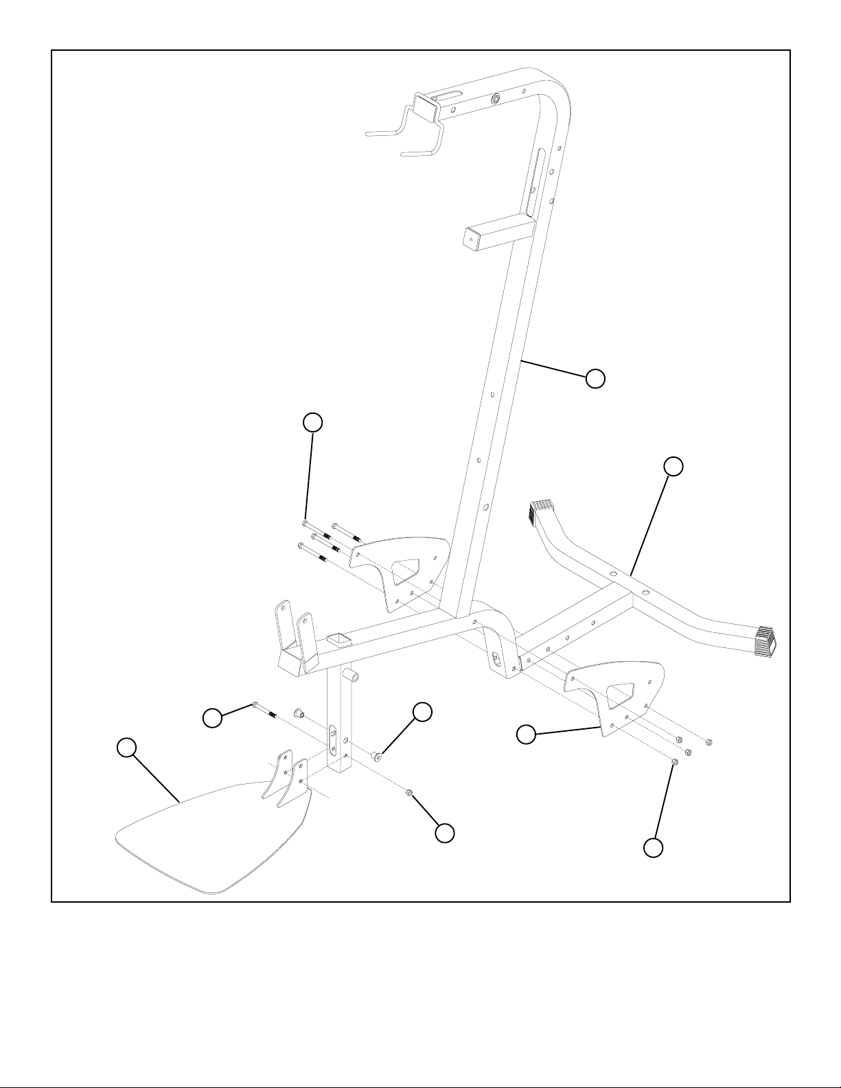
FIGURE 1
STEP 1:
• LOOSELY assemble two BASE PLATES (3) to the FRAME (1) and BASE (2) using four 3/8 X 3-3/4” BOLTS (30)
and four 3/8” LOCK NUTS (34). See FIGURE 1.
• Insert two 3/8 x 9/16” FLANGE SPACERS (41) into the upper holes in the FRAME (1) as shown in figure 1
• LOOSELY assemble the FOOTPLATE (62) to the lower holes in the FRAME (1) using one 3/8 x 3” BOLT (29) and one
3/8 LOCKNUT (34)
6
Page 7
23
22
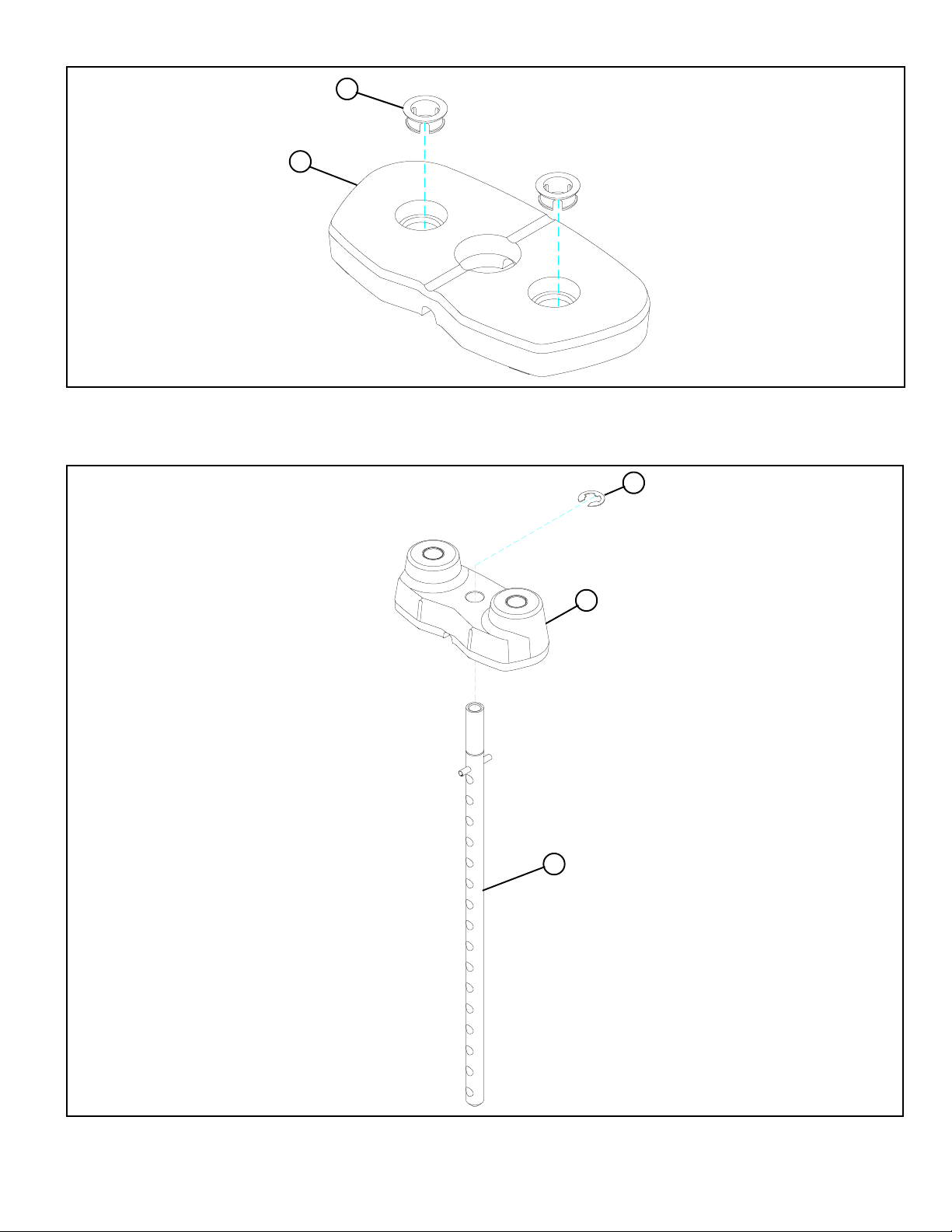
FIGURE 2
STEP 2:
• Insert two WEIGHT PLATE BUSHINGS (23) into each of the fifteen WEIGHT PLATES (22) as shown in FIGURE 2.
60
18
19
FIGURE 3
STEP 3:
• Slide the WEIGHT PLATE SHAFT (18) thru the hole in the HEAD PLATE (19), and lock in place using one E-RING (60) as shown
in FIGURE 3.
7
Page 8
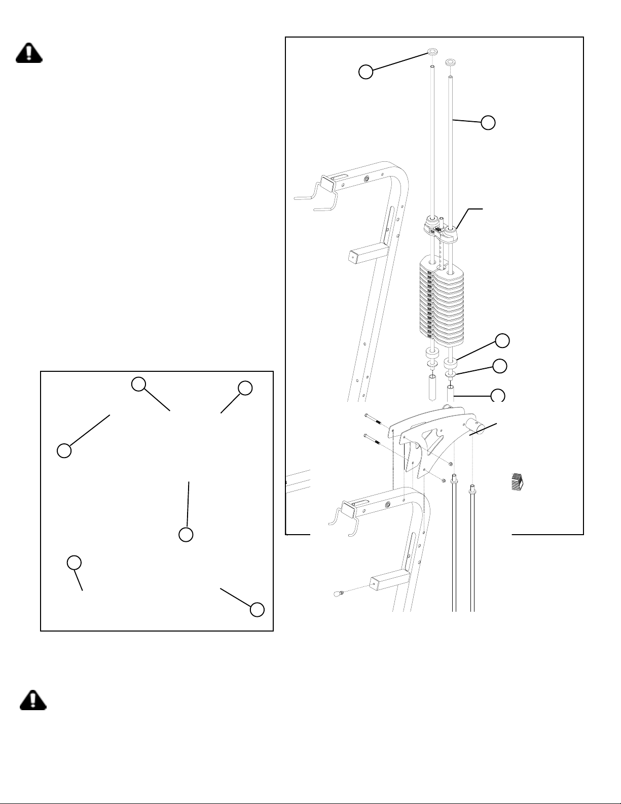
STEP 4:
• Insert two GUIDE RODS (16) into the BASE (2) as
shown on FIGURE 4. (NOTE: If the 220 SHROUD
OPTION was purchased, place the GUIDE RODS
(16) through the BOTTOM SHROUD BRACKET
(FOUND IN THE SHROUD KIT BOX) into the BASE
(2), as shown in FIGURE 4.
• (NOTE: Lubricate GUIDE RODS (16) with silicon
or teflon spray available at most hardware stores.)
• Slide the following items in order down each GUIDE
ROD (16), one WEIGHT STACK SPACER (45), one
3/4” FLAT WASHER (38) and one WEIGHT STACK
CUSHION (46)
• Using EXTREME CARE slide all fifteen
WEIGHT PLATES (22) down the GUIDE RODS (16)
onto the WEIGHT ST ACK CUSHIONS (46). Make sure
that the keyholes of the WEIGHT PLATES (22) are all
facing the right way .
• Slide the head plate assembly down GUIDE RODS
(16) onto the weight stack.
• Slide one SHAFT COLLAR (48) down each
GUIDE ROD (16).
48
16
HEAD
PLATE
ASSY
46
38
30
3/8 X 3-3/4
53
FIGURE 5
STEP 5:
5
34
4
45
220 SHROUD
BRACKET
OPTION ONL Y
2
FIGURE 4
16
• Carefully slide the RIGHT (5) and LEFT (4) BOOM PLATES onto the GUIDE RODS (16 )as shown in FIGURE 5 and loosely
assembly BOOM PLATES (5), (4) to frame (1) using two 3/8 x 3-3/4” BOLTS (30) and two 3/8” LOCK NUT (34)
[CAUTION MUST BE TAKEN NOT TO PULL GUIDE RODS (16) OUT OF BASE (2)]
• Screw ADJUSTABLE GLIDE (53) approximately 1/2” into FRAME (1) and tighten jam nut securely as shown
8
Page 9
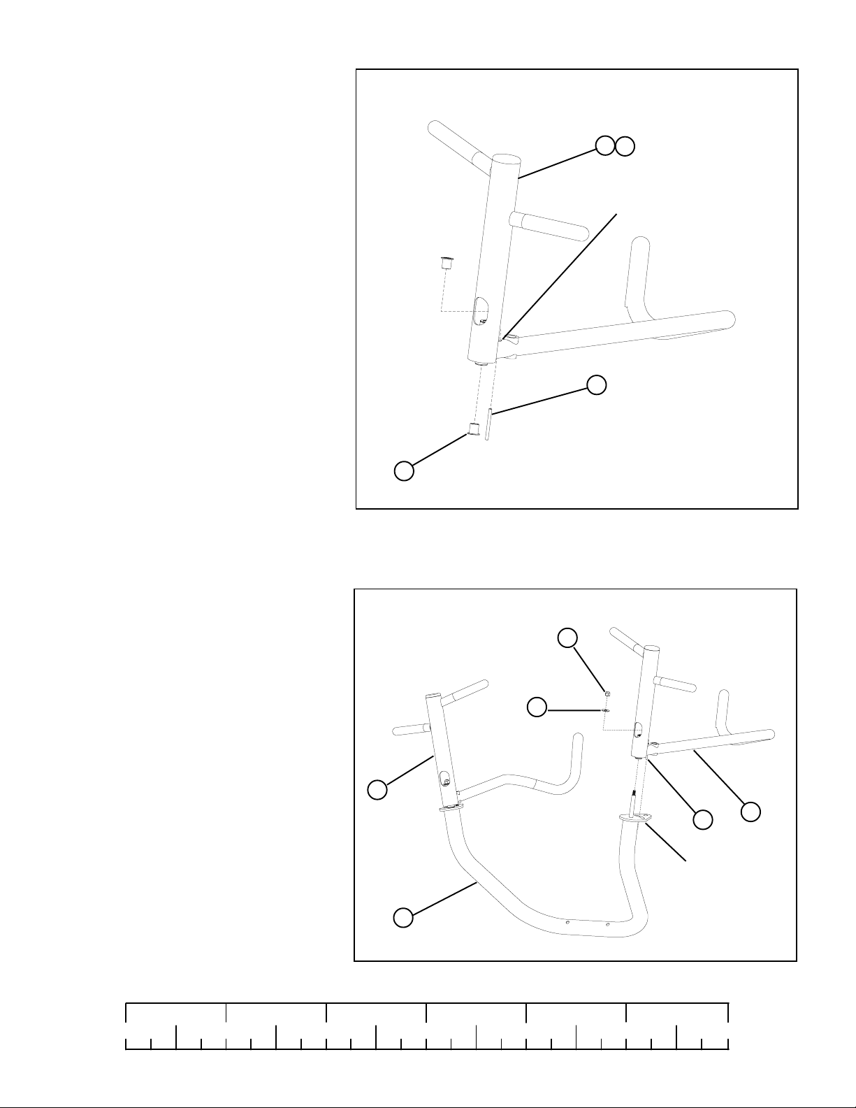
STEP 6:
• Insert two 1/2” FLANGE BEARINGS (40) into
the LEFT PRESS HANDLE (7) as shown in
FIGURE 6
• Using hammer tap one 5/16 X 2” ROLL PIN (47)
thru LEFT PRESS HANDLE (7) until it is flush
with other side of HANDLE as shown in
FIGURE 6
• Repeat STEP 6 for the RIGHT PRESS
ARM HANDLE (6)
40
22
6
47
FIGURE 6
7
22
FLUSH SIDE
STEP 7:
• Place LEFT PRESS HANDLE (7) onto PRESS
ARM (8). Make sure that the 5/16 X 2” ROLL
PIN (47) passes into the slot located in the plate
of the PRESS ARM (8)
• Once in place secure and tighten the LEFT
PRESS HANDLE (7) to PRESS ARM (8)
using one 3/8” WASHER (36) and one
3/8” LOCK NUT (34)
• IMPORTANT! Do not overtighten: PRESS
ARM should rotate freely
• Repeat STEP 7 for the RIGHT PRESS
ARM HANDLE (6)
NOTE:
Place PRESS ARM (8) upside down on floor as shown to complete this step
34
36
6
47
SLOT
8
7
FIGURE 7
1/2 1/2 1/2 1/2 1/2 1/2
0
1
2
345
9
6
Page 10
3/8 X 3”
29
36
9
34
Locking
Spring Pin
8
49
FIGURE 8
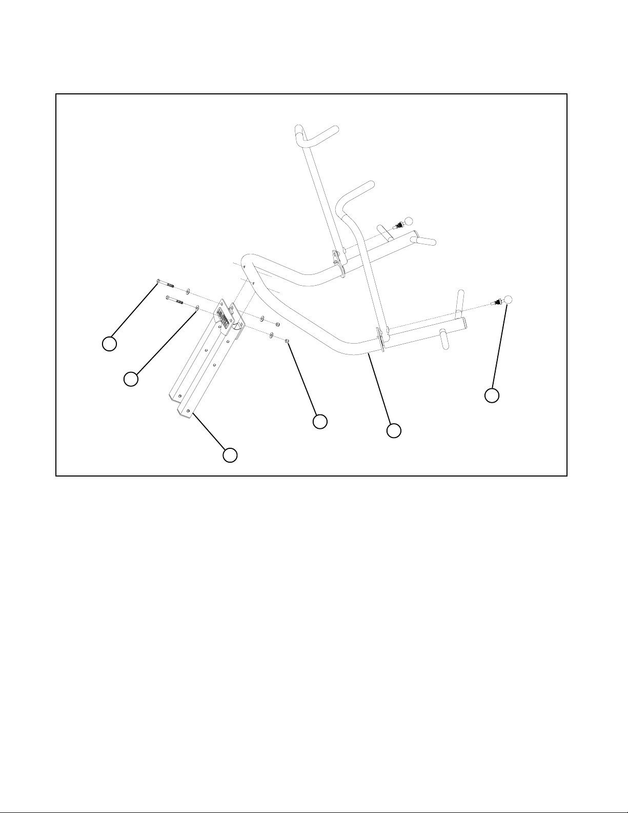
STEP 8:
• Place PRESS ARM (8) into PRIMARY PIVOT (9) and securely tighten using two 3/8 X 3” BOLTS (29), four 3/8” FLAT
WASHERS (36) two 3/8” LOCK NUTS (34)
• Insert and tighten two 3/8” LOCKING SPRING PINS (49) into PRESS HANDLES (6), (7).
• Lock PRESS ARMS (6), (7) into place using 3/8” LOCKING SPRING PINS (49)
• To disengage LOCKING SPRING PINS (49), pull out and twist 1/4 turn.
10
Page 11

33
1
1/2 X 8”
37
48
SECUREL Y
TIGHTEN
9
FIGURE 9
DO NOT
TIGHTEN
35
STEP 9
• SECUREL Y TIGHTEN ALL FRAME CONNECTION BEFORE PROCEEDING T O NEXT STEP
• SECURELY TIGHTEN top of both SHAFT COLLARS (48) flush to bottom of both BOOM PLATES (4),(5)
• Assemble the PRIMARY PIVOT (9) of the PRESS ARM ASSEMBLY to the top of the FRAME (1) using 1/2 X 8” BOLT (33),
two 1/2” FLAT WASHERS (37) and 1/2” LOW HT LOCK NUT (35). IMPORTANT! DO NOT TIGHTEN YET
1/2 1/2 1/2 1/2 1/2 1/2
0
1
2
345
11
6
Page 12
10
13
19
36
22
58
52
3/8 X 2-3/4”
28
61
1
50
FIGURE 10
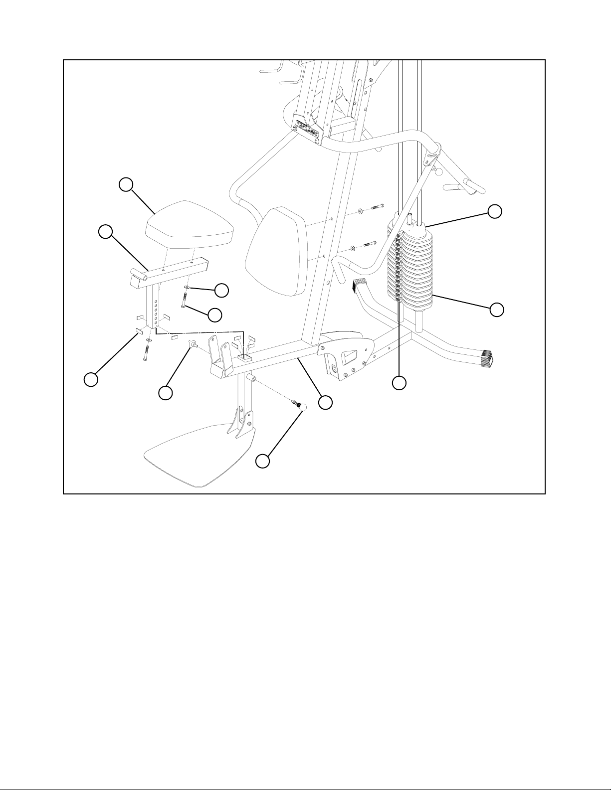
STEP 10:
• Apply WEIGHT STACK LABELS (61) to WEIGHTS (22) and HEAD PLA TE (19) as shown in FIGURE 10.
Begin with number one at the HEAD PLATE (19) with larger numbers in consecutive order towards bottom of weight stack.
• Apply four PARAGLIDES (58) to the INSIDE of the tube of FRAME (1) as shown. Apply the remaining four
PARAGLIDES (58) to the OUTSIDE and FLUSH TO BOTTOM of tube located on SEAT ADJUSTMENT (10)
• Securely assemble one SEAT PAD (13) to the SEAT ADJUSTMENT (10) using two 3/8 X 2-3/4” BOLTS (28) and two
3/8” WASHERS (36) as shown.
• Securely assemble one SEAT PAD (13) to the FRAME (1) using two 3/8 X 2-3/4” BOLTS (28) and two 3/8” WASHERS (36)
as shown.
• Gently insert SEAT ADJUSTMENT (10) into tube located on FRAME (1)
DO NOT FORCE THE SEAT ADJUSTMENT IN. THIS MAY CAUSE THE P ARAGLIDES T O TEAR.
• Securely tighten the SPRING PIN (50) to the FRAME (1) and hand tighten the THREE PRONG KNOB (52)
12
Page 13
55
1/2 X 4”
32
56
40
1
11
35
FIGURE 11
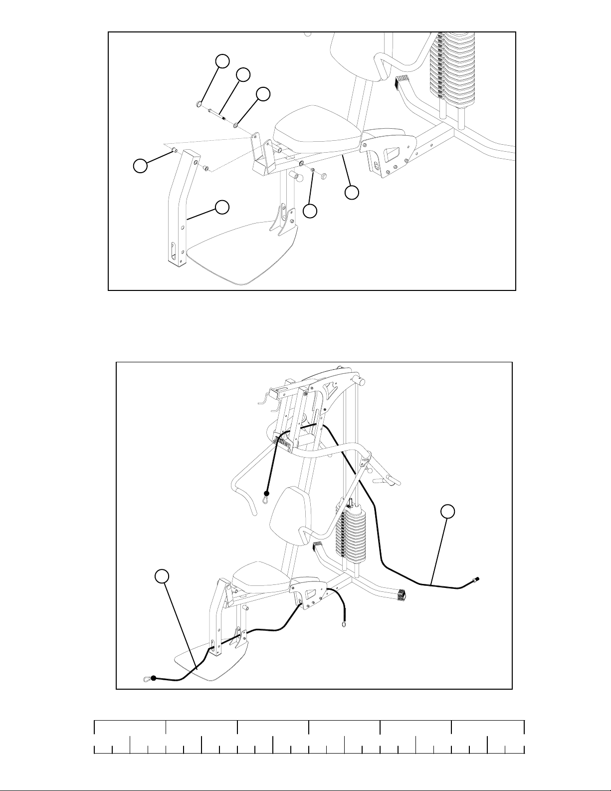
STEP 11:
• Insert two 1/2” FLANGE BEARINGS (40) into LEG PEDESTAL (1 1) as shown.
• Assemble the LEG PEDESTAL (11) to the FRAME (1) using one 1/2 X 4” BOLT (32), two RH WASHERS (56)
and one 1/2” LOW HT LOCK NUT (35)
• Assemble two RH CAPS (55) to the 1/2” RH WASHERS (56) as shown in FIGURE 11
21
STEP 12:
• Route LAT CABLE (20) and LOW CABLE (21) as shown in FIGURE 12
1/2 1/2 1/2 1/2 1/2 1/2
0
1
2
345
13
20
FIGURE 12
6
Page 14
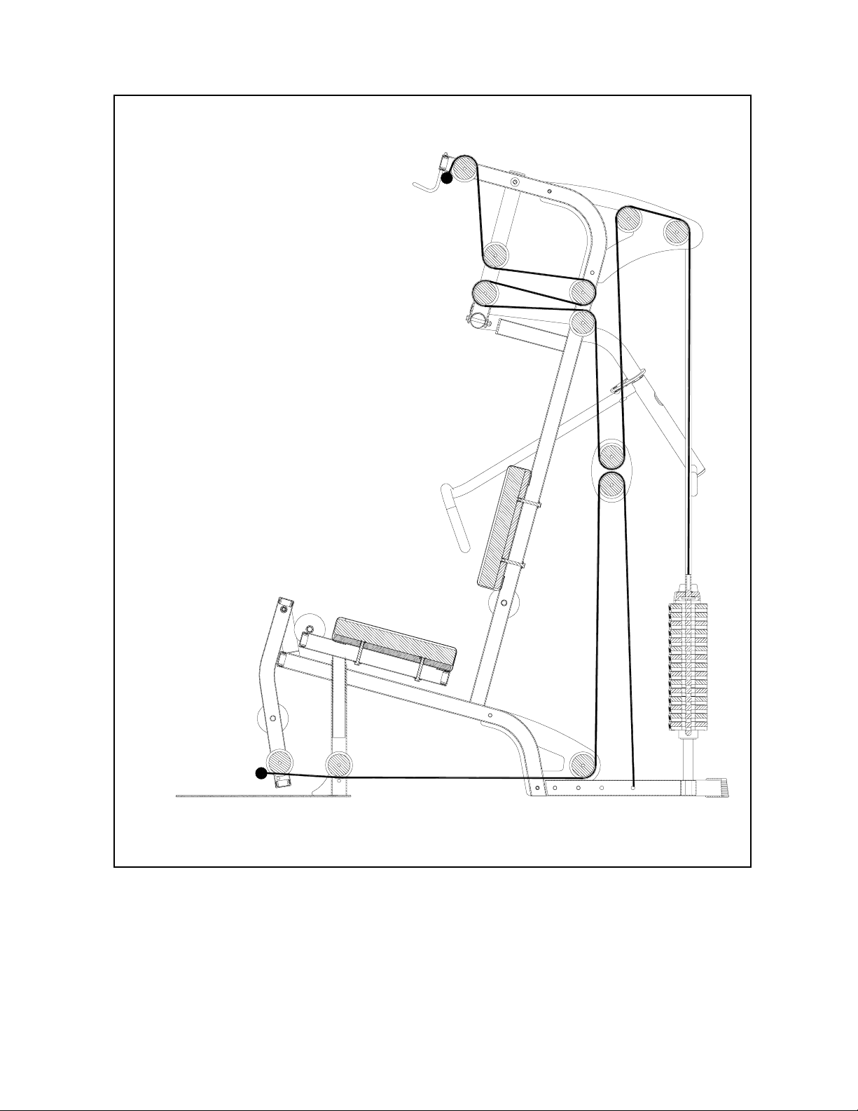
ILLUSTRA TION A
• ILLUSTRATION “A” used as cable routing reference for steps 13-16
NOTE: IF YOU PURCHASED A LEG PRESS, PLEASE REFER TO THE
CABLE ROUTING INSTRUCTIONS INCLUDED WITH THE LEG
PRESS KIT
14
Page 15
3/8 X 3-3/4”
30
42
31
3/8 X 8”
FIGURE 13
36
44
24
1
34
9
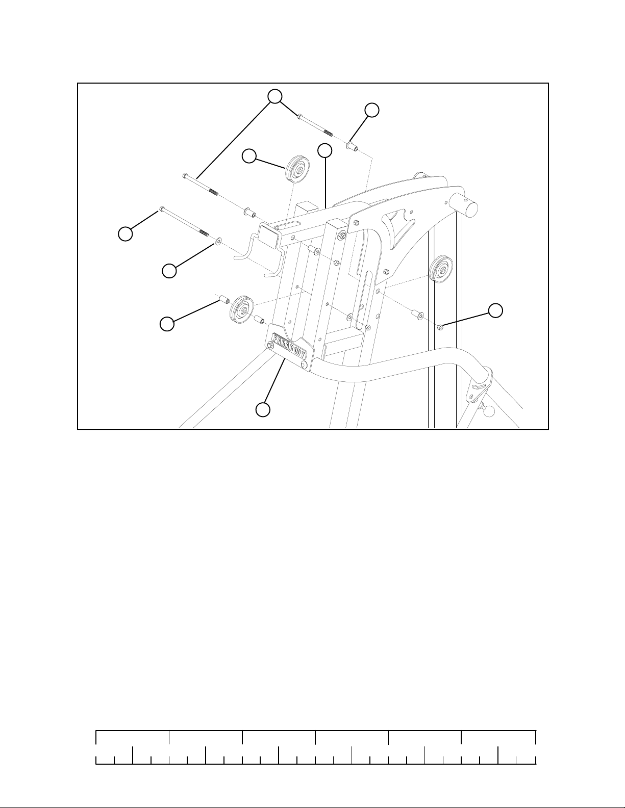
STEP 13:
• Refer to cable ILLUSTRATION “A” on page 11 for cable routing while installing pulleys.
• Assemble two 3-1/2” PULLEYS (24) into FRAME (1) using two 3/8 X 3-3/4” BOLTS (30), four 3/8 X 1-1/16”
FLANGE SPACERS (42) and two 3/8” LOCK NUTS (34) and tighten securely.
• Assemble one 3-1/2” PULLEY (24) into PRIMARY PIVOT (9) upper hole using one 3/8 X 8” BOLT (31),
two 3/8” FLAT WASHERS (36), two 3/8 X 1-3/16” SPACERS (44) and one 3/8” LOCK NUT (34) and tighten securely
1/2 1/2 1/2 1/2 1/2 1/2
0
1
2
345
15
6
Page 16
3/8 X 3-3/4”
30
24
3/8 X 8”
31
1
43
42
34
36
44
9
27
FIGURE 14
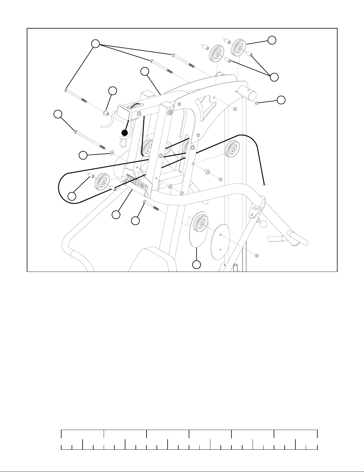
STEP 14:
• Refer to cable ILLUSTRATION “A” on page 11 for cable routing while installing pulleys.
• Assemble one 3-1/2” PULLEY (24) into the PRIMARY PIVOT (9) lower hole using one 3/8 X 8” BOLT (31),
two 3/8” FLAT WASHERS (36), two 3/8 X 1-3/16” SPACERS (44) and one 3/8” LOCK NUT (34) and tighten securely.
• Assemble one 3-1/2” PULLEY (24) to the FRAME (1) using one 3/8 X 3-3/4” BOLT (30), two 3/8 X 1-1/16”
FLANGE SPACERS (42), one 3/8” LOCK NUT (34) and tighten securely
• Loosely assemble one 3-1/2” PULLEY (24) between PULLEY PLATES (12) using one 3/8 X 1-3/4” BOLT (27) and
one 3/8” LOCK NUT (34).
• Assemble two 3-1/2” PULLEYS (24) between the left and right BOOM PLATES (4) and (5) using two 3/8 X 3-3/4” BOLTS (30),
four 3/8 X 1” SPACERS (43) and two 3/8” LOCK NUTS (34)
1/2 1/2 1/2 1/2 1/2 1/2
0
1
2
12
345
6
16
Page 17
DO NOT
OVERTIGHTEN
35
20
SECURELY
TIGHTEN
JAM NUT
18
FIGURE 15
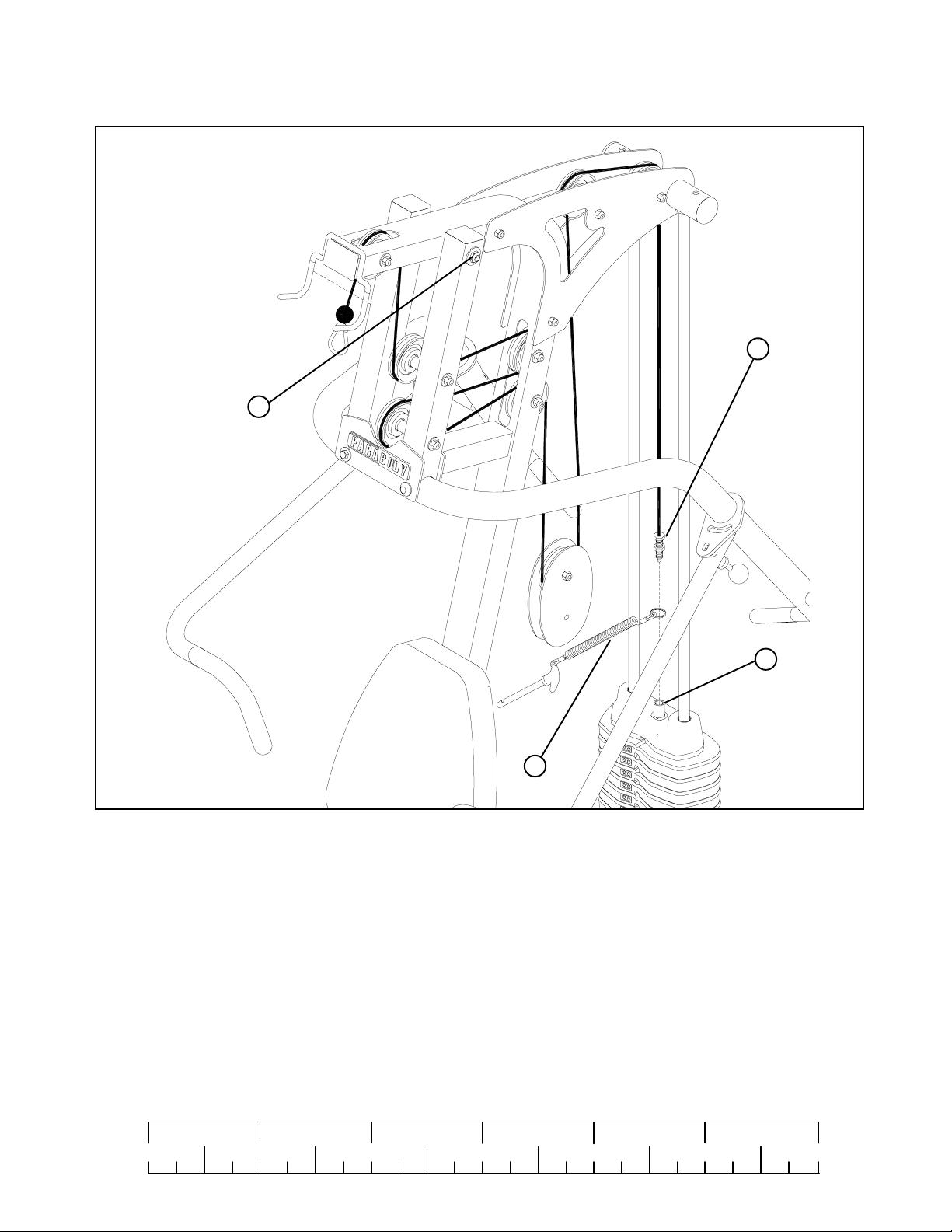
STEP 15
• Slip ring of WEIGHT SELECTOR PIN (51) down WEIGHT STACK SHAFT (18) and insert pin into one of the weights
• Screw end of LAT CABLE (20) into top of PLATE SHAFT (18) and securely tighten JAM NUT as shown in FIGURE 15
• Securely tighten 1/2” LOCK NUT (35) on PRIMARY PIVOT of PRESS ARM (9).
IMPORTANT! DO NOT OVER TIGHTEN: PRESS ARM SHOULD ROT A TE FREELY.
1/2 1/2 1/2 1/2 1/2 1/2
0
1
2
345
17
51
6
Page 18
11
3/8 x 3”
3/8 x 3-3/4”
24
FIGURE 16
29
30
21
1
34
42
34
36
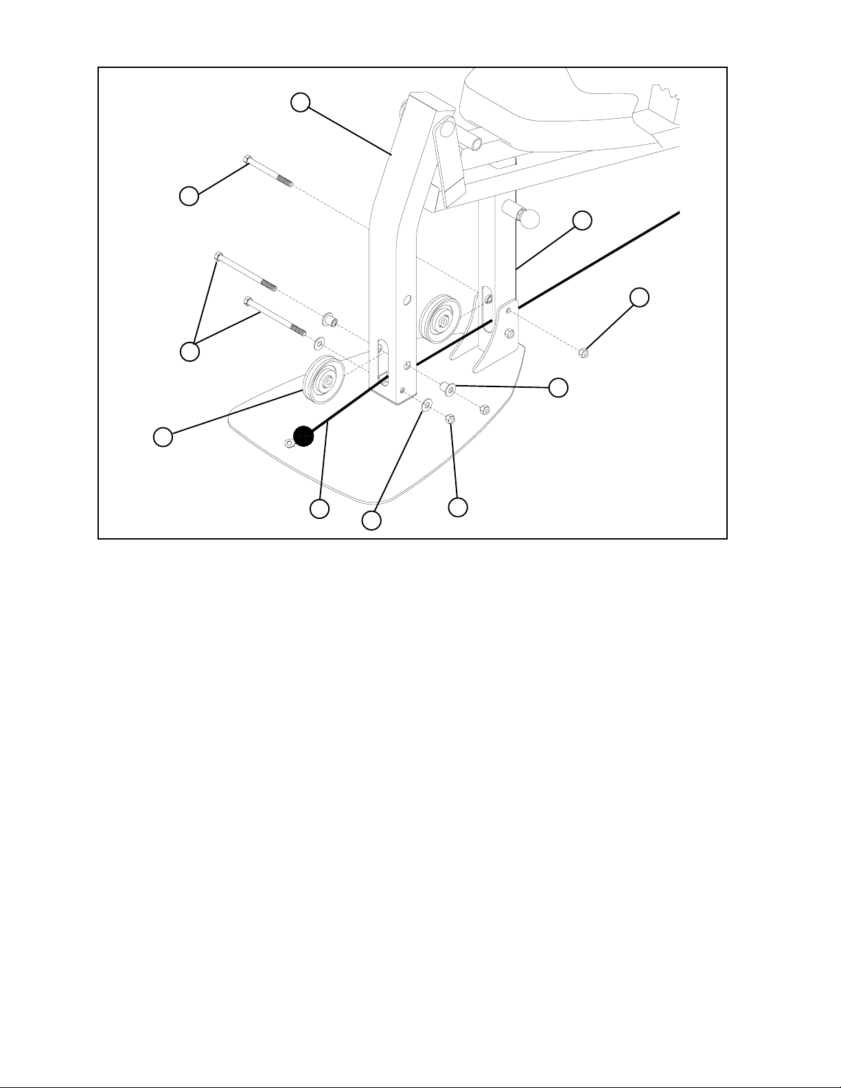
STEP 16:
• Refer to cable ILLUSTRATION “A” on page 11 for cable routing while installing pulleys.
• [CABLE MUST BE POSITIONED BETWEEN PULLEY AND LOWER BOLT ASSEMBLY ON
LEG PEDESTAL (11) AND FRAME (1)]
• Securely assemble the ball end of the LOW CABLE (21) and one 3-1/2” PULLEY (24) to the LEG PEDESTAL (11) using two
3/8 X 3-3/4” BOLTS (30), two 3/8” X 1-1/16” FLANGE SPACERS (42), two 3/8” WASHERS (36), and two 3/8” LOCKNUTS (34).
(NOTE: The LEG CABLE (21) should be routed over the retaining bolt as shown in FIGURE 16.)
• Securely assemble one 3-1/2” PULLEY (24) to the FRAME (1) using one 3/8 X 3” BOLTS (29), and one 3/8” LOCKNUT (34).
(NOTE: The LEG CABLE (21) should be routed over the retaining bolt as shown in FIGURE 16.)
18
Page 19
3/8 X 1 -3/4”
27
12
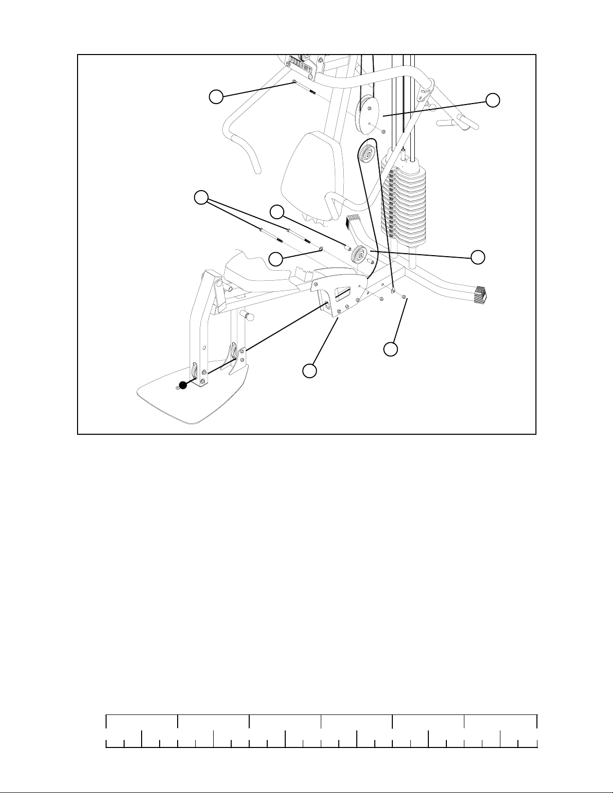
STEP 17:
3/8 X 3-3/4”
FIGURE 17
30
43
36
24
34
3
• Refer to cable ILLUSTRATION “A” on page 11 for cable routing while installing pulleys.
• Assemble one 3-1/2” PULLEY (24) between BASE PLATES (3) using one 3/8 X 3-3/4” BOLT (30), two 3/8 X 1” SPACERS
(43), one 3/8” LOCK NUT (34) and tighten securely.
• Loosely assemble one 3-1/2” PULLEY (24) between the PULLEY PLATES (12) using one 3/8 X 1-3/4” BOLT (27), and one
3/8” LOCK NUT (34).
• Secure end of LOW CABLE (21) using one 3/8 x 3-3/4 BOLT (30), one 3/8” FLAT WASHER (36) one 3/8” LOCK NUT (34)
as shown in FIGURE 17
• Tighten both 3-1/2” PULLEYS (24) located on PULLEY PLATES (12)
1/2 1/2 1/2 1/2 1/2 1/2
0
1
2
345
19
6
Page 20
10
39
1
54
15
14
11
FIGURE 18
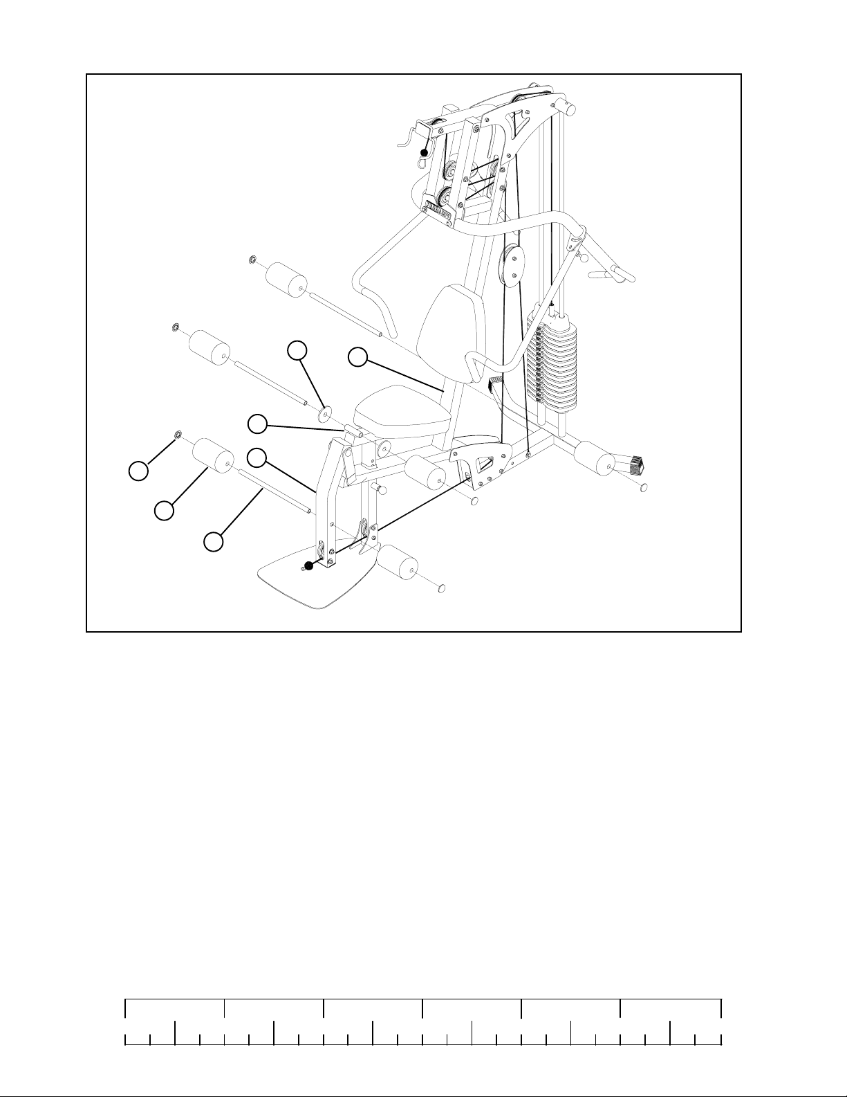
STEP 18:
• Attach two 4 X 7” ROLLER PADS (15) to the LEG PEDESTAL (11) using one 3/4 X 17” TUBE (14) and two
3/4” STARLOCK COLLARS (54) as shown in FIGURE 18.
• Attach two 4 X 7” ROLLER PADS (15) to the SEAT ADJUST (10) using one 3/4 X 1” TUBE (14), two PLASTIC
WASHERS (39) and two 3/4” STARLOCK COLLARS (54) as shown in FIGURE 18.
• Attach two 4 X 7” ROLLER PADS (15) to the FRAME (1) using one 3/4 X 17” TUBE (14) and two
3/4” STARLOCK COLLARS (54) as shown in FIGURE 18.
1/2 1/2 1/2 1/2 1/2 1/2
0
1
2
345
20
6
Page 21
17
PULL AND
TWIST TO
DISENGAGE
49
53
ADJUSTMENT
ADJUSTMENT
19
TIGHTEN
JAM NUT
SECURELY
57
25
26
51
FIGURE 19
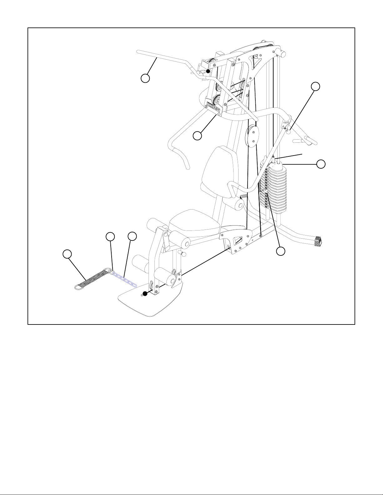
STEP 19:
• If upon completion of assembly, the HEAD PLATE (19) does not sit on top of the first WEIGHT PLATE (22), push the
HEAD PLATE (19) down, insert the WEIGHT SELECTOR PIN (51) and perform several repetitions at the press station.
This will relax the cable system and prevent the HEAD PLATE (19) from lifting up. See FIGURE 19
• If after completing previous step, the HEAD PLATE (19) still does not sit on top of the first WEIGHT PLATE (22) or if
there is excess slack in the cable system, adjust the threaded end of the LAT CABLE (20) and ADJUSTABLE GLIDE (53)
accordingly and retighten the jam nuts. See figure 19
• For maximum performance, the HEAD PLATE (19) should just barely sit on the top WEIGHT PLATE (22)
• Attach the ERGO BAR (17) to the ball end of LAT CABLE (20) using one SNAP LINK (57) as shown in FIGURE 19.
• Attach the ANKLE STRAP (25) to the 12 LINK CHAIN (26) using one SNAP LINK (57) as shown in FIGURE 19
Thank you for purchasing the ParaBody 220 Gym System. If unsure of proper use of equipment, call
your local ParaBody distributor or call the ParaBody customer service department at (800) 328-9714
21
Page 22

MAINTENANCE
Please note:
* We recommend cleaning your product (pads and frame) on a regular basis, using warm soapy
water. Touch-up paint can be purchased from your ParaBody customer service representative
at (800) 328-9714.
* Inspect equipment daily. T ighten all loose connections are replace worn parts immediately.
Failure to do so may result in serious injury
* Lubricate guide rods with a teflon based (or equivalent) lubricant on a regular basis
* PLEASE RECORD THE INFORMATION REQUESTED BELOW. IN THE EVENT
YOU MAY NEED SER VICE YOU WILL BE ASKED FOR THIS INFORMATION.
REMEMBER TO FILL OUT YOUR WARRANTY REGISTRATION CARD AND
MAIL BACK.
MODEL #________________________
SERIAL #_________________________
DATE OF PURCHASE: _____________
DEALERS NAME: _________________
DEALERS PHONE #_______________
Thank you for pur chasing the ParaBody 220 Gym System.
22
Page 23

LIMITED W ARRANTY
ParaBody extends the following LIMITED WARRANTY to the original owner of the ParaBody products. The Warranty terms apply to IN HOME USE ONL Y.
1. LIMITED WARRANTY ON FRAME AND WELDS. If the frame of the ParaBody product or a weld should crack or break, it will be repaired
or replaced by ParaBody. Terms: Lifetime – for so long as the Customer owns the ParaBody product.
2. LIMITED WARRANTY ON P ARTS. If the following part s are defective in material or workmanship, ParaBody will supply replacement parts:
all bolts, nuts, washers, bearings, bushings, pulleys, thumbscrews, collars, cable retaining clips, adjustable pre-stretch slides, roller pad
shafts, allen head bolts, weight selector pin, weight stack shaft, set screws, protector caps, adjustment chain, cotter pin, plunger , spring
and knob. Terms: Lifetime – for so long as the Customer owns the ParaBody product.
3. LIMITED WARRANTY ON CABLES AND UPHOLSTERY. If the coated cables or upholstery are defective in material or workmanship,
ParaBody will repair or replace them, at its option. Terms: Three (3) years.
4. CONDITIONS AND EXCEPTIONS. Any product misuse, abuse or alteration, any attempt to repair by a person other than an authorized
ParaBody Service Center, any improper assembly, accident, or any other condition resulting from occurrences beyond the control of
ParaBody will void this Limited Warranty .
5. REPLACEMENT AND REPAIR EXPENSES. ParaBody will provide only replacement parts or rep air under this warranty. The Owner is
responsible for all other costs. Such costs may include, but are not limited to: a. labor charges for service, removal, repair or reinstallation
of the ParaBody product or any component part; b. shipping, delivery , handling and administrative charges for returning parts to ParaBody;
and c. all necessary or incidental costs related to installation of the replacement parts.
6. SHIPPING . If shipping by the Owners is deemed necessary (in sole discretion of ParaBody), parts should be shipped in their original carton
or equivalent packaging, fully insured with shipping charges prepaid. ParaBody will not assume any responsibility for any loss or damage
incurred in shipping.
7. CLAIM PROCEDURES. If service on your ParaBody product is required during the warranty period, please contact our Customer Service
Department at 1-800-328-9714 for instructions regarding returning or replacing parts. Please have available the following information: (i) the
dealer’s name; (ii) the date of purchase; (iii) the serial # (s) of your product (the serial number location is called out on the final assembly
drawing included with your assembly instruction); (iv) a description of the nature of the problem.
8. OWNER’S RIGHT . This Limited W arranty gives you specific legal rights. Y ou may also have other rights, which vary depending on local law .
9. LIMITATION OF IMPLIED W ARRANTIES. All implied warranties, except to the extent prohibited by applicable law , shall have no greater
duration than the warranty period set forth above. There are no warranties which extend beyond the description in this Limited Warranty .
Because local laws do not allow limitations on how long an implied warranty lasts, the above limitations may not apply to you.
10. DISCLAIMER. No other express warranty has been made or will be made on behalf of ParaBody with respect to any ParaBody product or
the operation, repair or replacement of any ParaBody product. ParaBody shall not be responsible for injury , loss of use of the ParaBody
product, inconvenience, loss or damage to personal property, whether direct or indirect, and incidental or consequential damages, so the
above limitation or exclusion may not apply to you.
NOTES:
23
Page 24

LIFE FITNESS CONSUMER DIVISION
14150 Sunfish Lake Blvd. Ramsey Minnesota, 55303 U.S.A.
T el: 763.323.4500 Fax: 763.323.4797
800.328.9714 (T oll-free within the U.S. and Canada)
www.parabody.com
INTERNATIONAL OFFICES
Life Fitness Atlantic BV
Atlantic Headquarters
Bijdorpplein 25-31
2992 LB Barendrecht
The Netherlands
Phone: (180) 646 666
Fax: (180) 646 703
Life Fitness EUROPE GmbH
Siemensstrasse 3
85716 Unterschleissheim
Germany
Phone: (089) 31 77 51-0
Fax: (089) 31 77 51 99
Life Fitness Italia S.R.L.
V ia Elvas 92
39042 Bressanone
Italy
Phone: 39 (472) 835-470
Fax: 39 (472) 833-150
Life Fitness (UK) Ltd.
Queen Adelaide
Ely , Cambs CB7 4UB
United Kingdom
Phone CSS: (01353) 665507
Fax CSS: (01353) 666719
Life Fitness Benelux N.V.
Bijdorpplein 25-31
2992 LB Barendrecht
The Netherlands
Phone: 31 (180) 64 66 69
Fax: 31 (180) 64 66 99
Life Fitness Japan
8/F , Nippon Brunswick Building
5-27-7 Sendagaya
Shibuya-Ku, T okyo 151-0051
Japan
Phone: 81 (3) 3359-4309
Fax: 81 (3) 3359-4307
Life Fitness Asia Pacific Limited
Room 2610, Miramar T ower
132 Nathan Road, T simshatsui
Kowloon, Hong Kong
Phone: (852) 2891-6677
Fax: (852) 2575-6001
24
Life Fitness Do Brazil
Al. Rio Negro, 433-Predio 2-Sala 2
º andar (Confab)
3
Aplhaville-Barueri-Sao Paulo
CEP: 06454-904
Brazil
Phone: 55 (11)7295-2217
Fax: 55 (11) 7295-2218
 Loading...