


Leg Press 5
LP5 LEG PRESS 5
WARNING:
Read and follow all directions
for each step to insure proper
assembly of this product.
ASSEMBLY INSTRUCTIONS
CLASS H
P ART# 7357701
REV . B
1
V ersion: LP5A-101
Revision: 11/08/02
j
TABLE OF CONTENTS
Safety Statement.............2
General Notes..................3
Tools Required................3
Parts List.........................4
Assembly Instructions.....5-12
General Maintenance.......13
W arranty Statement.........14
Product Services.............15
Insert-Registration Card
IMPORTANT SAFETY INFORMATION
THERE IS A RISK ASSUMED BY INDIVIDUALS WHO USE THIS TYPE OF
EQUIPMENT. TO MINIMIZE RISK FOLLOW THESE RULES!
1. Before using, read all the warnings and instructions
on the use of this machine. Use only for intended
exercise. DO NOT modify the machine.
2. Obtain a medical exam before beginning any
exercise program.
3. Keep body and clothing free of all moving objects.
4. Inspect the machine before use. DO NOT use it if it
appears damaged. DO NOT attempt to fix a broken or
ammed machine. Notify your authorized ParaBody
dealer before use and have repairs made by an
authorized service technician.
6. Never pin the weights or prop plate into an elevated
position. DO NOT use the machine if found in this
condition. DO NOT attempt to fix. Notify your
authorized ParaBody dealer.
7. Inspect cables and their connections before using
machine. Pay particular attention to the cable ends.
DO NOT attempt to fix. Notify your authorized
ParaBody dealer before use and have repairs made by
an authorized service technician.
8. Make sure all spring loaded pull pins are fully
engaged in the adjustment position and fully tighten
thumbscrew before use.
5. Be certain that weight pin is completely inserted.
Use only the pin provided by the manufacturer. If
unsure, call your authorized ParaBody dealer.
9. Children must not be allowed near this machine.
Supervise teenagers.
.
NOTE: In a continual effort to improve our products, specifications are subject to change
2002 Life Fitness, a division of Brunswick Corporation. All rights reserved.
©
ParaBody is a trademark of Brunswick Corporation
www.parabody.com
2
IMPORTANT NOTES
Please note:
* Thank you for purchasing the ParaBody LP5 Leg Press. Please read these
instructions thoroughly and keep them for future reference.
* This product must be assembled on a flat, level surface to assure its proper function. DO NOT
securely tighten any frame connections until the entire frame has been assembled, unless
otherwise stated.
T ools Required for Assembly
* 3/4” wrench
* 9/16” wrench
* Ratchet with 3/4” and 9/16” sockets
* Adjustable wrench
* T ape measure
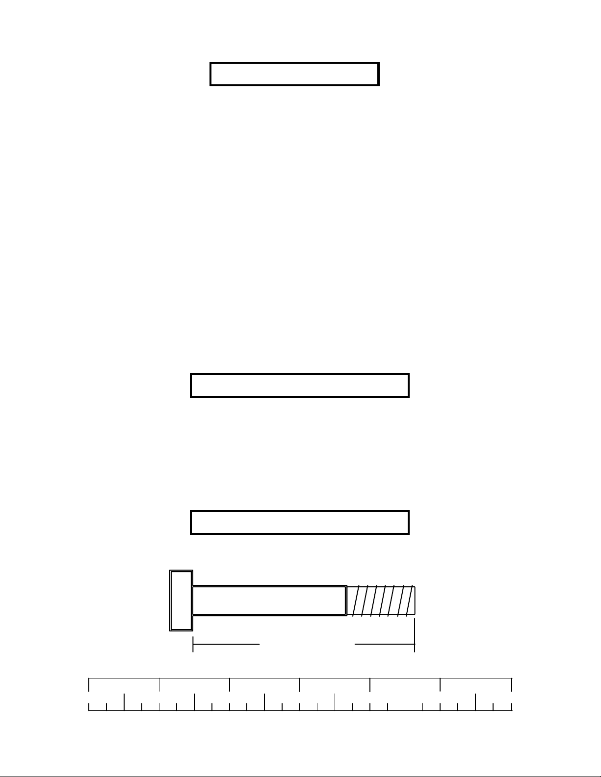
Bolt Length Ruler
NOTE: BOL T LENGTH IS MEASURED FROM THE UNDERSIDE OF THE HEAD OF THE BOLT.
BOLT LENGTH
BOL T LENGTH RULER:
1/2 1/2 1/2 1/2 1/2 1/2
0
1
2
345
3
6
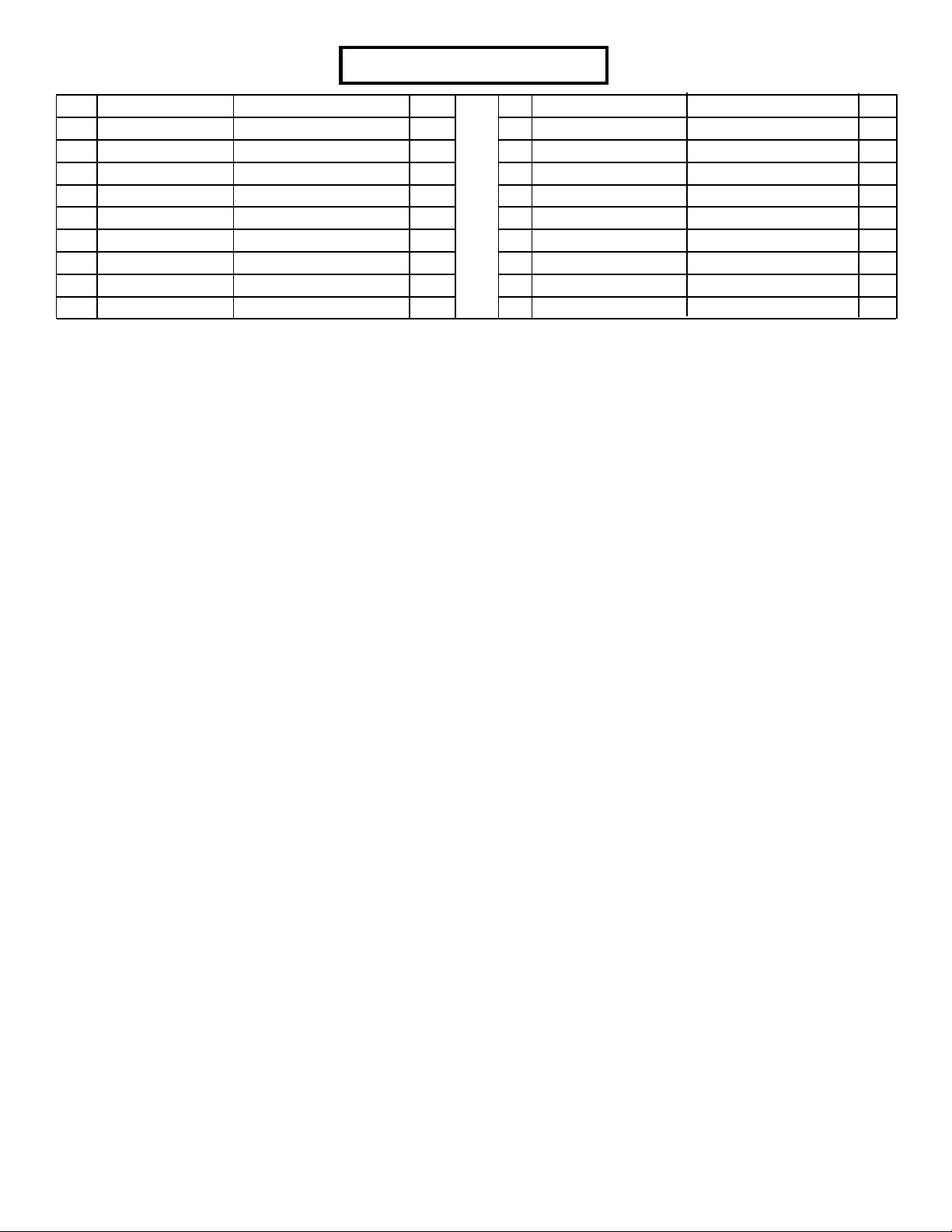
PARTS LIST
KEY
1
2
3
4
5
6
7
8
9
ACU04-1444
ACU04-1447
ACU04-1449
ACU04-1445
ACU04-1446
ACU04-1448
ACU02-1298
ACU07-0135
ACUDA1E03830016NB
PART #
DESCRIPTION
FRAME
SEA T ADJUST
HANDLE
MAIN ARM
SECOND ARM
FOOTPLATE
PULLEY BRACKET
PAD
3/8 X 3” BOL T
NOTE: Some of the component may be pre-assembled.
QTY
1
1
1
1
1
1
1
2
6
KEY
10
11
12
ACUDA1E02143413NB
13
14
15
16
17
ACUDACM04006007YB
PART #
ACUDC1250100020B
ACUDB2E03811000B
ACUDB2E01212000B
ACU11-0080
ACU05-0372
ACU06-0437
DESCRIPTION
3/8” FLA T W ASHER
3/8” LOCK NUT
1/2 X 4-3/4” BOL T
1/2” LOCK NUT
SPRING PIN KNOB
3/4 X 4” SHAFT
BUMPER, 1-1/2 X 2
SET SCREW , M4X0.7X6L
QTY
8
2
4
4
1
4
2
1
4
For assembly to the GS1, GS2, GS4, GS8 Gym Systems .
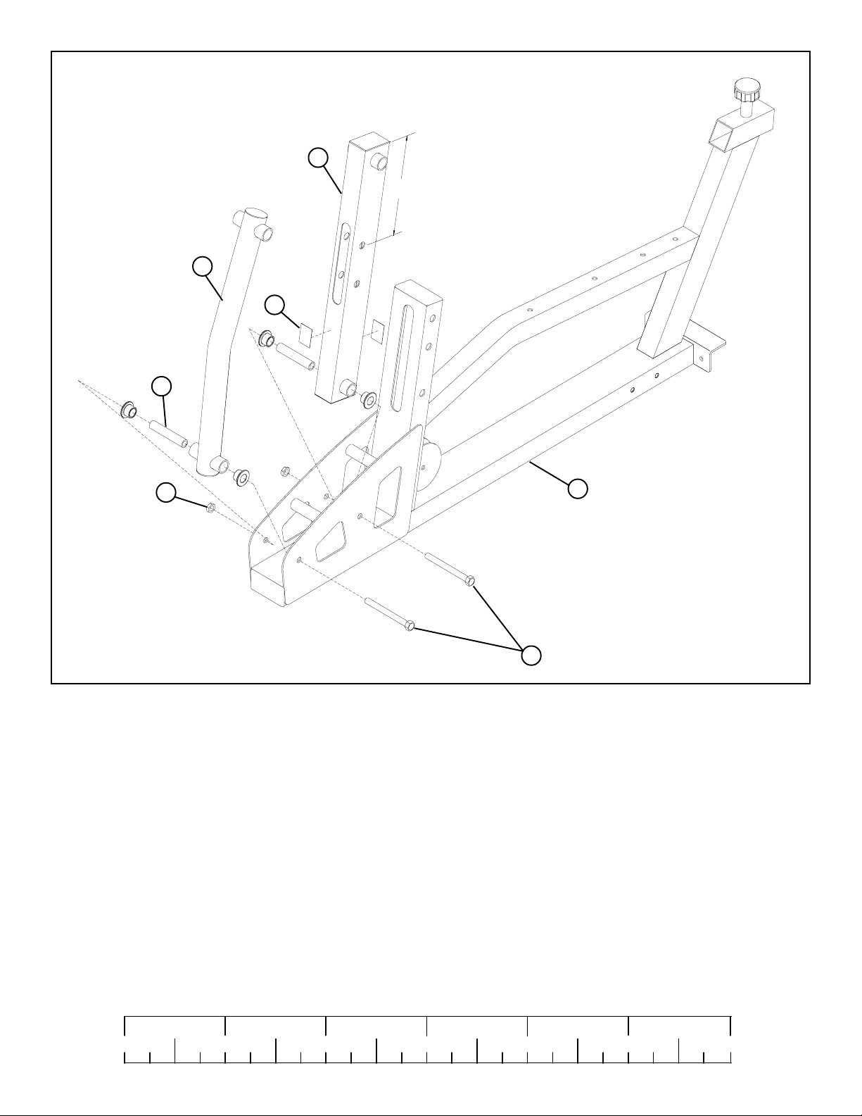
4
5
16
15
Make sure MAIN ARM
9−1/2"
is orientated correctly
13
12 1/2 X 4-3/4”
1
FIGURE 1
STEP 1:
• NOTE: Follow STEP 1 for the assembly of the LEG PRESS to the GS1, GS2, GS4 and GS8 Gym Systems. If you have the CM3 or GS6
Gym System proceed to STEP 2.
• NOTE: FLANGE BEARINGS SHOULD BE PRE-INSTALLED
• SECUREL Y assemble the SECOND ARM (5) to the FRAME (1) using one 1/2 X 4-3/4” BOL T (12), one 3/4 X 4” SHAFT (15)
and one 1/2” LOCK NUT (13). See FIGURE 1.
• SECUREL Y assemble the MAIN ARM (4) to the FRAME (1) using one 1/2 X 4-3/4” BOL T (12), two 3/4” FLANGE BEARINGS (14), one
3/4 X 4” SHAFT (15) and one 1/2” LOCK NUT (13). See FIGURE 1. (NOTE: Make sure MAIN ARM is orientated correctly , top hole
should be 9-1/2” from the top of arm as shown in FIGURE 1.)
• SECUREL Y assemble two 1-1/2 X 2 “ BUMPERS (16) to each side of the MAIN ARM (4) where the MAIN ARM (4) contacts the FRAME
(1) See FIGURE 1.
• Proceed to to STEP 3.
1/2 1/2 1/2 1/2 1/2 1/2
0
1
2
345
5
6
 Loading...