


893103 PRO SYSTEM
ASSEMBLY INSTRUCTIONS
Part # 6753901 |
1 |
Revision:10/27/97 |
IMPORTANT NOTES
Please note: WELCOMETOTHEWORLDOF Serioussteel!
*Thank you for purchasing the Parabody 893103 PRO SYSTEM. Please read these instructions thoroughly and keep them for future reference. This product must be assembled on a flat, level surface to assure its proper function.
*We recommend cleaning your product (pads and frame) on a regular basis, using warm soapy water. Touch-up paint can be purchased from your Parabody customer service representative
at (800) 328-9714.
There is a risk assumed by individuals who use this type of equipment. To minimize risk, please follow these rules:
1.Inspect equipment daily. Tighten all loose connections and replace worn parts immediately. Failure to do so may result in serious injury.
2.Do not allow minors or children to play on or around this equipment.
3.Exercise with care to avoid injury.
4.If unsure of proper use of equipment, call your local Parabody distributor or call the Parabody customer service department at (800) 328-9714.
5.Consult a physician before beginning any exercise program.
Tools Required for Assembly
*3/4” wrench
*9/16” wrench
*Ratchet with 3/4” and 9/16” sockets
*Adjustable wrench
*Tape measure
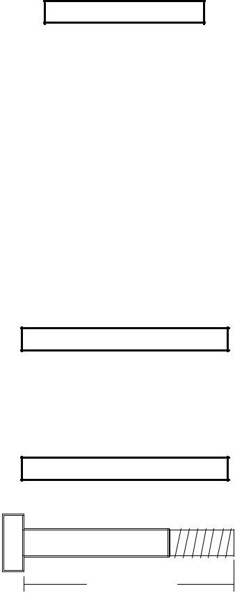
Bolt Length Ruler
NOTE: BOLT LENGTH IS MEASURED FROM THE UNDERSIDE OF THE HEAD OF THE BOLT.
BOLT LENGTH
BOLT LENGTH RULER:
|
1/2 |
|
1/2 |
|
1/2 |
|
1/2 |
|
1/2 |
|
|
1/2 |
|
|||||||||||
0 |
|
|
1 |
|
|
2 |
|
|
3 |
|
|
4 |
|
|
5 |
|
6 |
|||||||
|
|
|
|
|
|
|
|
|
|
|
|
|
|
|
|
|
|
|
|
|
|
|
|
|
2
PARTS LIST
KEY |
PART # |
DESCRIPTION |
QTY |
|
KEY |
PART # |
DESCRIPTION |
QTY |
1 |
6566603 |
UPRIGHT FRAME |
1 |
|
29 |
3102933 |
3/8 X 2” BOLT |
7 |
2 |
6566702 |
TOP BOOM |
1 |
|
30 |
3102502 |
1/2” WASHER |
3 |
3 |
6546302 |
CARRIAGE |
1 |
|
31 |
3102501 |
3/8” WASHER |
6 |
4 |
6566903 |
BENT TUBE |
1 |
|
32 |
3102602 |
1/2” LOCK WASHER |
3 |
5 |
6567002 |
UPRIGHT |
2 |
|
33 |
3102601 |
3/8” LOCK WASHER |
2 |
6 |
6581102 |
LAT BAR |
1 |
|
34 |
3102801 |
1/2” LOCK NUT |
9 |
7 |
6569802 |
BOOM SUPPORT LEFT |
1 |
|
35 |
3102804 |
1/2” LOW HT LOCK NUT |
1 |
8 |
6567302 |
BOOM SUPPORT RIGHT |
1 |
|
36 |
3102802 |
3/8” LOCK NUT |
17 |
9 |
6567502 |
SAFETY RAIL |
2 |
|
37 |
3103801 |
SNAP LINK |
3 |
10 |
6567803 |
SWIVEL KNEE SUPPORT |
1 |
|
38 |
3108102 |
QUICK LINK |
2 |
11 |
6516502 |
PULLEY BRACKET |
1 |
|
39 |
6075906 |
CHAIN |
1 |
12 |
6568102 |
LOW ROW ATTACHMENT |
1 |
|
40 |
6412001 |
3/8” SPRING PIN ASSEMBLY |
3 |
13 |
6568303 |
BEARING HOUSING |
1 |
|
41 |
3104901 |
3/4” FLANGE BEARING |
4 |
14 |
6568603 |
PEC ARM RIGHT |
1 |
|
42 |
6480301 |
3/8”FLANGE SPACER |
8 |
15 |
6568703 |
PEC ARM LEFT |
1 |
|
43 |
6145801 |
THUMBSCREW |
2 |
16 |
6570403 |
CENTER PULLEY BRACKET |
1 |
|
44 |
6692601 |
3 X 2” END CAP |
1 |
17 |
6542402 |
1-3/4 X 5-1/4” PLATE |
2 |
|
45 |
3119301 |
2-1/2” ROUND END CAP |
2 |
18 |
6274402 |
LOW ROW BAR |
1 |
|
46 |
6236701 |
1-3/4” SQ. END CAP |
1 |
19 |
6597402 |
BACK PAD |
1 |
|
47 |
6405201 |
2” SQ. END CAP |
8 |
20 |
6194601 |
4 X 7” ROLLER PAD |
2 |
|
48 |
6467001 |
COVER CAP |
2 |
21 |
6176201 |
4 X 12” ROLLER PAD |
2 |
|
49 |
6484101 |
STARLOCK COLLAR |
2 |
22 |
6189501 |
UPRIGHT LABELS |
2 |
|
50 |
3103102 |
1 X 8” GRIP |
4 |
23 |
3116201 |
3-1/2” PULLEY |
11 |
|
51 |
3116001 |
1-1/4” SQ. RUBBER BUMPER |
1 |
24 |
6576201 |
PEC CABLE |
1 |
|
52 |
3120702 |
3/4” CAP NUT |
2 |
25 |
6492201 |
LAT & LOW ROW CABLE |
2 |
|
53 |
6140701 |
1” SQ. GLIDE |
10 |
26 |
3102918 |
1/2 X 3-1/4” BOLT |
7 |
|
54 |
6416601 |
1-1/2 X 3/4” GLIDE |
3 |
27 |
3102910 |
1/2 X 3” BOLT |
6 |
|
55 |
6177001 |
NON-SKID STRIP |
2 |
28 |
3102922 |
3/8 X 2-3/4” BOLT |
12 |
56 |
6533501 |
CABLE RETAINING CLIP |
4 |
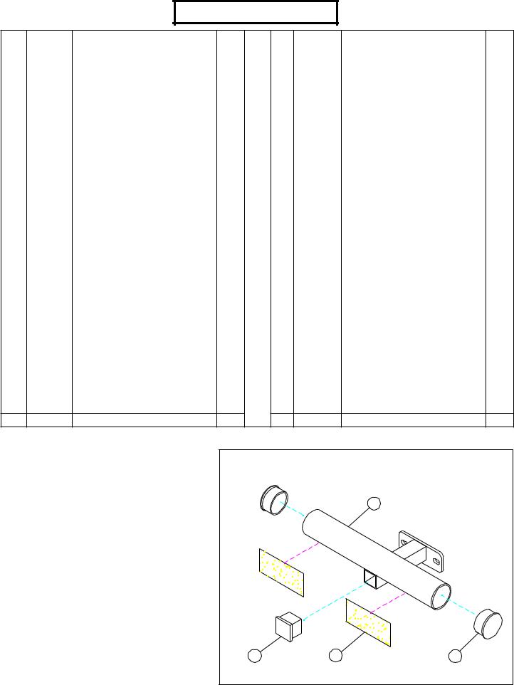
STEP 1: |
|
FIGURE 1 |
|
|
|
||
• Insert one 1-3/4” SQ. END CAP (46) to the LOW |
|
|
|
|
|
||
ROW ATTACHMENT (12) as shown in FIGURE 1. |
|
|
|
|
|
||
• Insert two 2-1/2” ROUND END CAPS (45) to the |
|
|
|
12 |
|
||
LOW ROW ATTACHMENT (12) as shown in |
|
|
|
|
|
||
FIGURE 1. |
|
|
|
|
|
|
|
• Attach two NON-SKID STRIPS (55) to the LOW |
|
|
|
|
|
||
ROW ATTACHMENT (12) as shown in FIGURE 1. |
|
|
|
|
|
||
|
|
|
|
46 |
55 |
45 |
|
|
|
|
|
3 |
|
|
|
47
1
47
4 |
34 |
48
12
1/2 X 3-1/4” 26
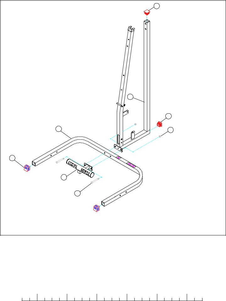
FIGURE 2
STEP 2:
•Assemble two COVER CAPS (48) to the ends of the BENT TUBE (4) as shown in FIGURE 2.
•Insert two 2” SQ. END CAPS (47) to the ends of the UPRIGHT FRAME (1) as shown in FIGURE 2.
•SECURELY assemble the LOW ROW ATTACHMENT (12) to the BENT TUBE (4) and UPRIGHT FRAME (1) using two 1/2 X 3-1/4” BOLTS (26) and two 1/2” LOCKNUTS (34) as shown in FIGURE 2.
|
1/2 |
|
1/2 |
|
1/2 |
|
1/2 |
|
1/2 |
|
|
1/2 |
0 |
1 |
2 |
3 |
4 |
5 |
6 |
||||||
4

5
22
3/8 X 2-3/4” 28
36
4
FIGURE 3
STEP 3:
• LOOSELY assemble the UPRIGHTS (5) to the BENT TUBE (4) using four 3/8 X 2-3/4” BOLTS (28) and four 3/8” LOCKNUTS (36) as shown in FIGURE 3.
• Attach UPRIGHT LABELS (22) to both of the UPRIGHTS (5) as shown in FIGURE 3.
5

40
54
TRIM EXCESS
43
9
FIGURE 4
STEP 4:
•Attach ten 1-1/2 X 3/4” GLIDES (54) to both SAFETY RAILS (9) as shown in FIGURE 4.
•SECURELY assemble one SPRING PIN ASSEMBLY (40) to both SAFETY RAILS (9) as shown in FIGURE 4.
•Thread one THUMBSCREW (43) into both SAFETY RAILS (9) as shown in FIGURE 4.
53
3
53
51
FIGURE 5
STEP 5:
•Apply eight 1” SQ. GLIDES (53) to the inside of the CARRIAGE (3) as shown in FIGURE 5.
•Attach one 1-1/4” SQ. RUBBER BUMPER (51) to the bottom of the CARRIAGE (3) as shown in FIGURE 5.
|
1/2 |
|
1/2 |
|
1/2 |
|
1/2 |
|
1/2 |
|
|
1/2 |
0 |
1 |
2 |
3 |
4 |
5 |
6 |
||||||
6
 Loading...