

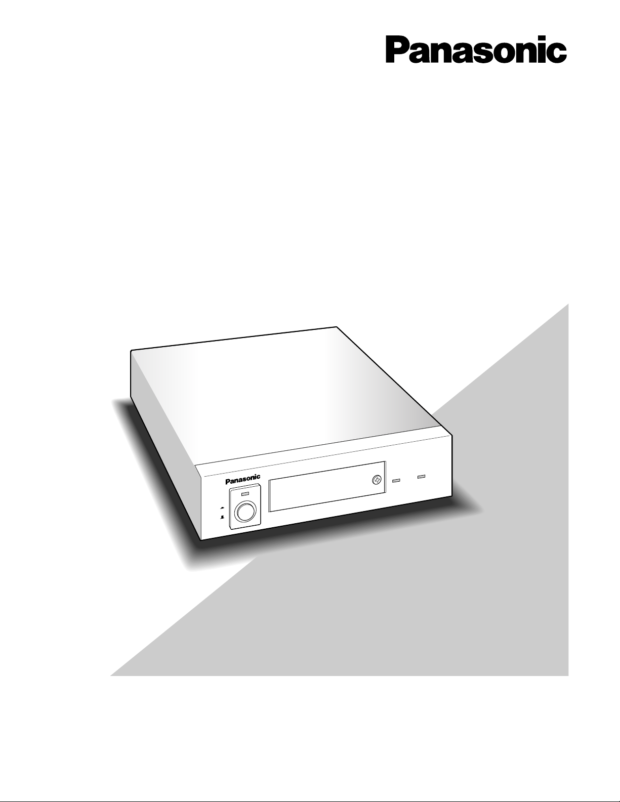
Page 1
Before attempting to connect or operate this product,
please read these instructions carefully and save this manual for future use.
Model No. WJ-MP204C
Data Multiplex Unit
Operating Instructions
POWER
ON
OFF
ALARM
ALARM
SUSPEND
Data Multiplex Unit WJ-MP204C
Page 2
2
The serial number of this product may be found on the bottom of the unit.
You should note the serial number of this unit in the space
provided and retain this book as a permanent record of your
purchase to aid identification in the event of theft.
Model No.
Serial No.
WARNING:
To reduce the risk of fire or electric shock, do not expose this appliance to rain or moisture.
The lightning flash with arrowhead symbol, within an equilateral triangle, is
intended to alert the user to the presence of uninsulated "dangerous voltage"
within the product's enclosure that may
be of sufficient magnitude to constitute a
risk of electric shock to persons.
The exclamation point within an equilateral triangle is intended to alert the user
to the presence of important operating
and maintenance (servicing) instructions
in the literature accompanying the appliance.
CAUTION: TO REDUCE THE RISK OF ELECTRIC SHOCK,
DO NOT REMOVE COVER (OR BACK).
NO USER-SERVICEABLE PARTS INSIDE.
REFER SERVICING TO QUALIFIED SERVICE PERSONNEL.
CAUTION
RISK OF ELECTRIC SHOCK
DO NOT OPEN
SA 1965
SA 1966
NOTE: This equipment has been tested and found to comply
with the limits for a Class A digital device, pursuant to Part
15 of the FCC Rules. These limits are designed to provide
reasonable protection against harmful interference when the
equipment is operated in a commercial environment. This
equipment generates, uses, and can radiate radio frequency
energy and, if not installed and used in accordance with the
instruction manual, may cause harmful interference to radio
communications.
Operation of this equipment in a residential area is likely to
cause harmful interference in which case the user will be
required to correct the interference at his own expense.
FCC Caution: To assure continued compliance, (example use only shielded interface cables when connecting to computer or peripheral devices). Any changes or modifications
not expressly approved by the party responsible for compliance could void the user’s authority to operate this equipment.
For U.S.A
Caution:
Before attempting to connect or operate this product,
please read the label on the bottom.
ENGLISH VERSION
Page 3

3
IMPORTANT SAFETY INSTRUCTIONS
1) Read these instructions.
2) Keep these instructions.
3) Heed all warnings.
4) Follow all instructions.
5) Do not use this apparatus near water.
6) Clean only with dry cloth.
7) Do not block any ventilation openings. Install in accordance with the manufacturer's instructions.
8) Do not use near any heat sources such as radiators, heat registers, stoves, or other apparatus (including amplifiers) that
produce heat.
9) Do not defeat the safety purpose of the polarized or grounding-type plug. A polarized plug has two blades with one wider
than the other. A grounding-type plug has two blades and a third grounding prong. The wide blade or the third prong are
provided for your safety. If the provided plug does not fit into your outlet, consult an electrician for replacement of the
obsolete outlet.
10) Protect the power cord from being walked on or pinched particularly at plugs, convenience receptacles and the points
where they exit from the apparatus.
11) Only use attachments/accessories specified by the manufacturer.
12) Use only with the cart, stand, tripod, bracket, or table specified by the manufacturer, or sold with the apparatus. When a
cart is used, use caution when moving the cart/apparatus combination to avoid injury from tip-overs.
13) Unplug this apparatus during lightning storms or when unused for long periods of time.
14) Refer all servicing to qualified service personnel. Servicing is required when the apparatus has been damaged in any way,
such as power-supply cord or plug is damaged, liquid has been spilled or objects fallen into the apparatus, the apparatus
has been exposed to rain or moisture, does not operate normally, or has been dropped.
S3125A
Page 4

4
CONTENTS
IMPORTANT SAFETY INSTRUCTIONS ........................................................................................................................................ 3
PREFACE ...................................................................................................................................................................................... 5
FEATURES .................................................................................................................................................................................... 5
PRECAUTIONS ............................................................................................................................................................................. 6
MAJOR OPERATING CONTROLS AND THEIR FUNCTIONS ...................................................................................................... 7
■ Front View ............................................................................................................................................................................. 7
■ Rear View .............................................................................................................................................................................. 8
INSTALLATION ............................................................................................................................................................................. 9
■ Mounting in the Rack ............................................................................................................................................................ 9
CONNECTION & SETTING ........................................................................................................................................................... 10
● Basic Connection (PS
•
Data) ............................................................................................................................................ 10
● Multi-unit Connection (PS
•
Data) ....................................................................................................................................... 11
● Video Multiplexer Connection (PS
•
Data) ..........................................................................................................................12
● Digital Disk Recorder Connection (PS
•
Data) ................................................................................................................... 13
● Matrix Switcher Connection (Camera Communication) ................................................................................................... 14
● DIP Switch Setting ............................................................................................................................................................ 15
● Unit Number Setting ......................................................................................................................................................... 15
● Alarm/Remote Terminal Setting ........................................................................................................................................ 16
● Internal Setting .................................................................................................................................................................. 17
● RS-485 DATA Port Connection (PS
•
Data) ........................................................................................................................ 17
● RS-485 Terminal Connection (Camera Communication) ................................................................................................. 18
SETUP PROCEDURES ................................................................................................................................................................. 19
■ Prior to setup ........................................................................................................................................................................ 19
● Confirmation ..................................................................................................................................................................... 19
● To open or close the setup menu ..................................................................................................................................... 19
● Buttons used in the setup ................................................................................................................................................. 19
● Setup menus ..................................................................................................................................................................... 20
■ Setup Menus for PS
•
Data ..................................................................................................................................................... 21
● Communication setup (PS
•
Data) ...................................................................................................................................... 21
● System setup (PS
•
Data) ................................................................................................................................................... 21
■ Setup Menus for Camera Communication Protocol ............................................................................................................. 24
● Communication setup (Camera Communication) ............................................................................................................ 24
● System setup (Camera Communication Protocol) ........................................................................................................... 25
OPERATION ................................................................................................................................................................................. 28
■ Camera Selection ................................................................................................................................................................. 28
● Front Panel Operation ....................................................................................................................................................... 28
● WV-CU360C Operation .................................................................................................................................................... 28
■ Alarm Operation ................................................................................................................................................................... 28
● Alarm Input ....................................................................................................................................................................... 28
● Processing ........................................................................................................................................................................ 28
● Alarm Output .................................................................................................................................................................... 28
● Alarm Reset ...................................................................................................................................................................... 29
● Alarm Suspension ............................................................................................................................................................. 29
SPECIFICATIONS ......................................................................................................................................................................... 30
STANDARD ACCESSORIES ......................................................................................................................................................... 31
ALL RESET ................................................................................................................................................................................... 31
Page 5

5
PREF ACE
FEATURES
The Data Multiplex Unit WJ-MP204C is designed for installation in a surveillance system, offering system flexibility
particularly when camera control functions are required.
The unit multiplexes video signals with control data and
VD2 sync into a coaxial cable. This makes installations
between the unit and cameras easy.
Front Panel Operations
• Camera channel selection from 1 to 4
• Alarm reset/suspension
• WJ-MP204C setup menus
In/Out Features
• Four camera inputs with multiplexed control and VD2
• Four camera outputs looped through
• Spot (monitor) in/out
• VS/VD (sync) in/out
• RS-485 for use of the Camera Communication Protocol
• RS-485 for use of the PS
•
Data protocol
• Alarm in/out and remote in/out, switchable
Displayed Image on the monitor screen
• Camera channel selected
• Alarm channel activated
• Setup menus
Camera control with WV-CU360C
• Pan/tilt head and housing control
• Motorized lens control (focus, zoom, iris, etc.)
• Camera setup menus
Alarm Function
• Inputs: Video Motion Detection by the camera/Alarm
input to the terminal.
• Output: Signal is supplied to respective alarm terminal.
• Preset: The camera moves to the preset position when
an alarm operates.
• Display: The activated channel picture and the channel
number are displayed.
The monitor and system controller can be located distant
from the camera site thanks to the use of a coaxial cable
and an RS-485 cable.
The unit includes two protocols, Panasonic Security Data
(PS
•
Data) and the Camera Communication one, selectable
with DIP switches.
Page 6

6
PRECAUTIONS
• Refer all work related to the installation of this
product to qualified service personnel or system
installers.
• Do not block the ventilation opening or slots on the
cover.
To prevent the appliance temperature from rising, place
the appliance at least 5 cm (2 inches) away from the
wall.
• Do not drop metallic parts through slots.
This could permanently damage the appliance. Turn
the power off immediately and refer servicing to qualified service personnel.
• Do not attempt to disassemble the appliance.
To prevent electric shock, do not remove screws or
covers.
There are no user-serviceable parts inside. Refer maintenance to qualified service personnel.
• Handle the appliance with care.
Do not strike or shake, as this may damage the appliance.
• Do not expose the appliance to water or moisture,
nor try to operate it in wet areas.
Do take immediate action if the appliance becomes
wet. Turn the power off and refer servicing to qualified
service personnel. Moisture can damage the appliance
and also cause electric shock.
• Do not use strong or abrasive detergents when
cleaning the appliance body.
Use a dry cloth to clean the appliance when it is dirty.
When the dirt is hard to remove, use a mild detergent
and wipe gently.
• Do not operate the appliance beyond its specified
temperature, humidity or power source ratings.
Do not use the appliance in an extreme environment
where high temperature or high humidity exists.
Use the appliance at temperatures within –10°C +50°C (14°F - 122°F) and a humidity below 90 %.
The input power source for this appliance is 120 V AC
60 Hz.
Page 7
7
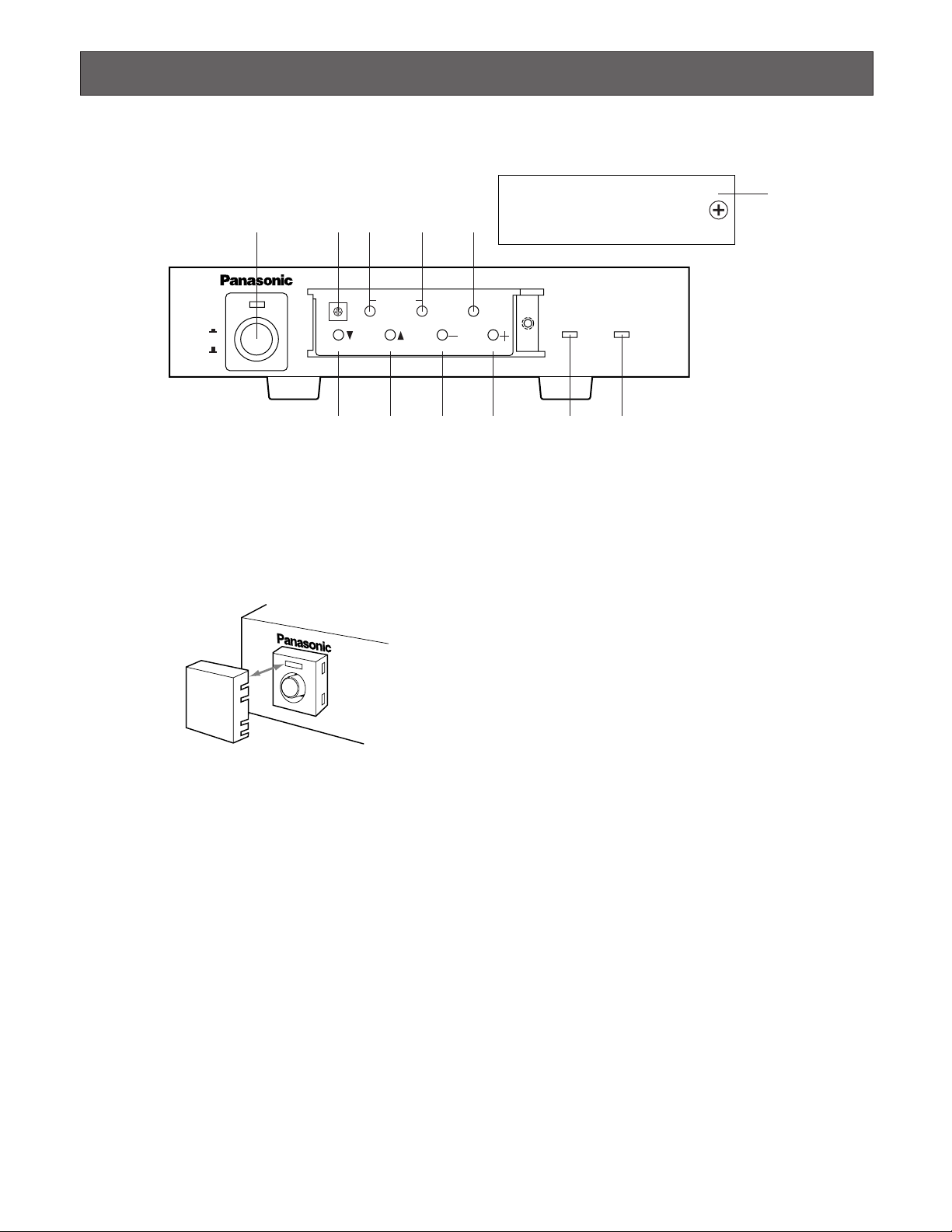
MAJOR OPERATING CONTROLS AND THEIR FUNCTIONS
q Power switch and power Indicator (POWER ON OFF)
To turn on or off the power of the unit, press the switch.
The indicator is lit while the power is supplied.
Note: Use the switch protector (supplied) to avoid acci-
dental power-off of the unit.
w Unit number switch (UNIT 0-8)
This switch specifies the WJ-MP204C unit number in a
PS
•
Data protocol system, or camera unit numbers in
the Camera Communication Protocol system. Refer to
page 15 for more information.
e Alarm reset button (ALARM)
This button resets the activated alarm. When this button
is pressed, the alarm indicator turns off, alarm display
“ALARM ***” on the monitor disappears, alarm status
output signal turns inactive on the rear, and an alarm
reset pulse is supplied on the rear.
Note: “***” is a camera number.
r Alarm suspend/set button (SUSPEND/SET)
In normal operation, pressing this button suspends the
activated alarm mode until it is pressed next.
In the setup operation, pressing this button confirms the
presently selected parameter or opens a submenu.
t Setup/escape button (SETUP/ESC)
Holding down this button opens or closes the setup
menu.
In the setup operation, pressing this button returns to
an upper layer setup menu.
y Down/1 button (C)
Selects camera #1 in normal operation.
Moves the cursor downward in the setup operation.
u Up/2 button (D)
Selects camera #2 in normal operation.
Moves the cursor upward in the setup operation.
i –/3 button (–)
Selects camera #3 in normal operation.
Decrements the parameter in the setup operation.
o +/4 button (+)
Selects camera #4 in normal operation.
Increments the parameter in the setup operation.
!0 Alarm indicator (ALARM)
This indicator blinks when an alarm is activated,
changes to steady light when the preset time elapses,
and turns off when the alarm is reset.
!1 Alarm suspension indicator (ALARM SUSPEND)
This is lit while the alarm is suspended.
!2 Front cover
Put the cover and fix it with the screw on the front panel
when these buttons are not required.
POWER
ON
OFF
ALARM
Data Multiplex Unit WJ-MP204C
ALARM
SUSPEND
1234
ESCSET
RESET
SUSPEND SET UP
ALARM
UNIT
0
9
8
7
6
5
4
3
2
1
q w e r
y
u i o !0 !1
t
!2
■ Front View
SWITCH
PROTECTOR
Page 8
8
■ Rear View
@1 Camera Input Connector 1-4 (CAMERA IN 1 2 3 4)
These connectors accept the composite video signal
supplied by the cameras while passing through the
control data and VD2 sync signal.
@2 Camera Output Connector 1-4 (CAMERA OUT 1 2 3
4)
These connectors supply the looped through composite
video of the camera image. Any one of these connectors can accept VD2 sync from a connected device
such as a Video Multiplexer that accepts composite
video while sending VD2. Refer to page 23 for details.
@3 Spot Input Connector (SPOT IN)
Accepts a spot output signal supplied from another
Data Multiplex Unit when connecting more than one unit
in a daisy fashion.
@4 Spot Output Connector (SPOT OUT)
Supplies the composite video signal of the selected
camera, alarm activated camera or WJ-MP204C setup
menus to display them on the monitor. This BNC is usually connected with a monitor. In a multi-unit connection this is connected with SPOT IN of the next unit
unless the unit is at the tail end.
@5 VS/VD Input Connector (VS/VD IN)
Accepts C. Sync, VBS or VD sync input. The unit will
follow the sync input while supplying sync through the
VS/VD OUT connector to other devices. Cameras will
follow VD2 sync supplied through the CAMERA IN connectors. You need to set up VS/VD INPUT in the SYSTEM menu window when connecting. Refer to page 23
for details.
Note: Sync source should comply with the EIA RS-170
standard. Do not input signals having a high jitter
content such as VCR playback signals.
@6 VS/VD Output Connector (VS/VD OUT)
Supplies a sync signal depending on the input to the
VS/VD IN connector and setting of the MODE DIP
switch #1. Refer to page 15 and 23 for details.
@7 Alarm/Remote Terminal (ALARM/REMOTE)
Pins #6-9 are used in one out of four ways most suitable
to your system requirements: alarm input, alarm output,
remote input, and remote output. Input/output is specified by the position of an internal connector while
alarm/remote is specified in the SYSTEM setup menu.
Refer to page 16 and 26 for more details.
@8 RS-485 Terminal (RS-485)
These terminals are exclusively used for devices compatible with “Camera Communication Protocol” such as
the WJ-SX350 Matrix Switcher and WJ-FS616C Video
Multiplexer. Through R (receive) and T (transmit) terminals, the unit exchanges communication data for camera control and other commands in 2-line half duplex or
4-line full duplex mode.
@9 Data Port (DATA)
This port is exclusively used to communicate with
devices compatible with “PS
•
Data protocol” such as
the WJ-FS316/416 Video Multiplexer, Digital Disk
Recorder and System Controller WV-CU360C. Using
this port is incompatible with using RS-485 terminal
above.
#0 DIP Switch (MODE)
Data communication mode and sync setting are specified with this switch. Refer to page 15 for more information.
#1 Signal grounding terminal (SIGNAL GND)
#2 Power cord
RT
IN IN
CAMERA RS485
ABABG
VS/VDSPOT DATA
ALARM / REMOTE
MODE
SIGNAL GND
4321
OUT OUTINOUT
4321
@1
@2
@4 @6
@8
@9 #0
@3 @5 @7 #1 #2
Page 9
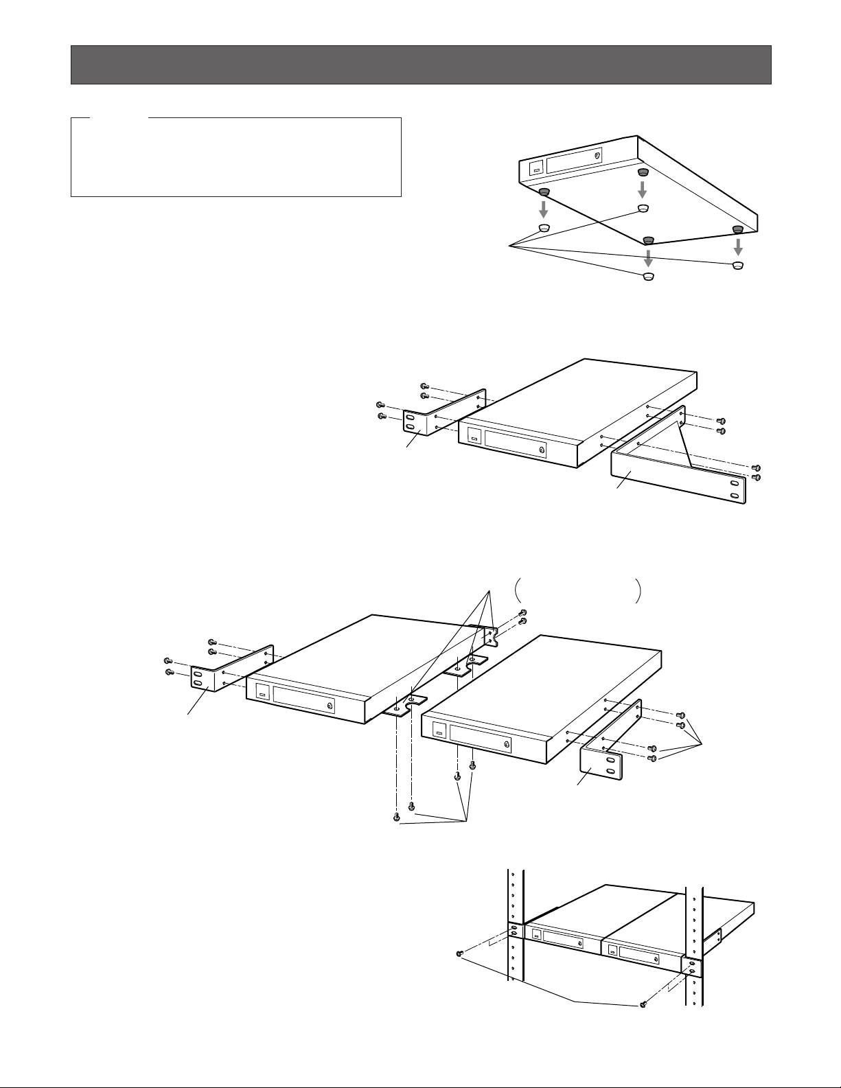
9
Joint metal
Remove 2 screws from
the rear beforehand.
Rack mounting
bracket (small)
Rack mounting
bracket (small)
Mount screw
Binding head
(M3x8)
Mount screw
Flat head (M3x6)
■ Mounting in the Rack
Remove the four rubber feet by removing the four screws
from the bottom of the WJ-MP204C.
● Mounting One WJ-MP204C with the
WV-Q204/1
1. Fix the mounting brackets (large and small) on both
sides of the WJ-MP204C with the eight supplied screws
(M3x8) to the WV-Q204/1.
● Mounting two WJ-MP204Cs with the
WV-Q204/2
1. Place the joint metals on the WJ-MP204Cs as shown
below and fix them with the supplied screws (M3x6) to
the WV-Q204/2.
Note: Remove the two screws from the rear of each
WJ-MP204Cs.
2. Install the WJ-MP204Cs with the rack
mounting brackets on the rack using
four screws (not supplied).
Cautions:
• Do not block the ventilation opening or slots in the
cover to prevent the appliance from overheating.
Always keep the temperature in the rack within +45°C
(113°F).
• Secure the rear of the appliance to the rack by using
additional mounting brackets (procured locally), if the
rack is subject to vibration.
• Do not use tapping screws for installing the WJMP204C on the rack with the rack mounting brackets.
INSTALLATION
Rubber feet
Rack mounting
bracket (small)
Rack mounting
bracket (large)
Rack mounting screws
Only qualified service personnel or system installers
should make all rack mountings, connections or internal
settings. If adjustments are required, please refer to the
Service Manual available for this product.
Warning!
Page 10
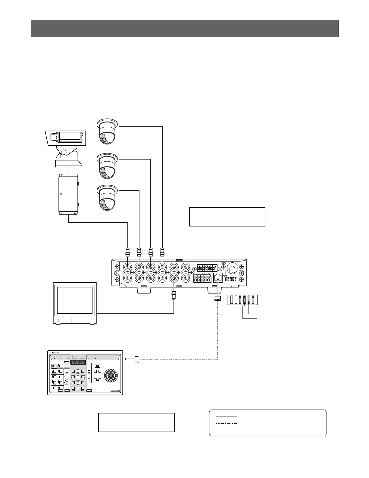
10
Shown below are some system connection examples using Data Multiplex unit with peripheral devices in PS•Data (Panasonic
Security Data) or the Camera Communication Protocols. Note that all system devices in a system should use the same protocol.
● Basic Connection (PS
•
Data)
Up to four cameras are connected with the unit at a camera site while a System Controller operates camera selection, pan/tilt
and lens control at a control site.
CONNECTION & SETTING
TR
IN IN
CAMERA RS485
ABABG
VS/VDSPOT DATA
ALARM / REMOTE
MODE
SIGNAL GND
4321
OUT OUTINOUT
4321
Camera
Monitor
System Controller WV-CU360C
Video signal
RS485 signal
(Panasonic Security Data mode)
1 ch
2 ch
3 ch
4 ch
Camera Site
Control Site
4-Line
Termination ON
Panasonic Security Data mode
MODE
Termination ON
Controller No. 1
OPERATE LOGIN ALARM
CAM SETUP
PROGRAM
PROGRAM
PRESET
UNIT A
IRIS
CLOSE OPEN
NEAR FAR
WIDE TELE
FOCUS
ZOOM
AUTO FOCUS
IRIS RESET
AUTO
SETUP
ALM SUSPEND
FUNCTION
CAM FUNCTION
MULTI SCREEN SELECT
DEF
WIPER
EL-ZOOM
SHIFT
ALM RESET
VTR CAM
STILL
–
+
ALM RECALL
PATROL
LEARN
PATROL
STOP
AUX 1
AUX 2
B/W UNIT
SEQ PAUSE
SLOW
SEQUENCE
PATROL PLAY
HOME/PRESET
UNIT B
MON
CAM
LOGOUT
ESC SET
UP
LR
DOWN
BUSY PROHIBITED
MONITOR
UNIT
CAMERA
System Controller
WV-CU
360
Page 11

11
● Multi-unit Connection (PS
•
Data)
A maximum of four units can be connected in a daisy fashion, from SPOT OUT to SPOT IN and so on, and finally from SPOT
OUT to the monitor.
SD RD
IN IN
CAMERA RS485
ABABG
VS/VDSPOT DATA
ALARM / REMOTE
MODE
SIGNAL GND
4321
OUT OUTINOUT
4321
TR
IN IN
CAMERA RS485
ABABG
VS/VDSPOT DATA
ALARM / REMOTE
MODE
SIGNAL GND
4321
OUT OUTINOUT
4321
SD RD
IN IN
CAMERA RS485
ABABG
VS/VDSPOT DATA
ALARM / REMOTE
MODE
SIGNAL GND
4321
OUT OUTINOUT
4321
TR
IN IN
CAMERA RS485
ABABG
VS/VDSPOT DATA
ALARM / REMOTE
MODE
SIGNAL GND
4321
OUT OUTINOUT
4321
5 ch
6 ch
7 ch
8 ch
1 ch
2 ch
3 ch
4 ch
System Controller WV-CU360C
Unit Address 2Unit Address 1
VS/VD OUT
SPOT IN
SPOT
OUT
Termination OFF
MODE
VS/VD IN VS/VD OUT
SPOT IN
4-Line
Termination ON
Controller No. 1
4-Line
Termination OFF
Panasonic Security
Data mode
Monitor
MODE
Panasonic Security
Data mode
OPERATE LOGIN ALARM
CAM SETUP
PROGRAM
PROGRAM
PRESET
UNIT A
IRIS
CLOSE OPEN
NEAR FAR
WIDE TELE
FOCUS
ZOOM
AUTO FOCUS
IRIS RESET
AUTO
SETUP
ALM SUSPEND
FUNCTION
CAM FUNCTION
MULTI SCREEN SELECT
DEF
WIPER
EL-ZOOM
SHIFT
ALM RESET
VTR CAM
STILL
–
+
ALM RECALL
PATROL
LEARN
PATROL
STOP
AUX 1
AUX 2
B/W UNIT
SEQ PAUSE
SLOW
SEQUENCE
PATROL PLAY
HOME/PRESET
UNIT B
MON
CAM
LOGOUT
ESC SET
UP
LR
DOWN
BUSY PROHIBITED
MONITOR
UNIT
CAMERA
System Controller
WV-CU
360
Video signal
RS485 signal
(Panasonic Security Data mode)
Camera Site
Control Site
VD OUT
13 ch
14 ch
15 ch
16 ch
9 ch
10 ch
11 ch
12 ch
Unit Address 4Unit Address 3
VS/VD IN VS/VD OUT
SPOT IN
SPOT OUT
SPOT OUT
SPOT SW OUTINOUTINSPOT SW IN OUT
Termination OFF
MODE
VS/VD IN
4-Line
4-Line
Termination ON
Panasonic Security
Data mode
MODE
Panasonic Security
Data mode
SPOT OUT
0
9
8
7
6
5
4
3
2
1
UNIT #1
0
9
8
7
6
5
4
3
2
1
UNIT #2
0
9
8
7
6
5
4
3
2
1
UNIT #3
0
9
8
7
6
5
4
3
2
1
UNIT #4
Page 12

12
SD RD
IN IN
CAMERA RS485
ABABG
VS/VDSPOT DATA
ALARM / REMOTE
MODE
SIGNAL GND
4321
OUT OUTINOUT
4321
TR
IN IN
CAMERA RS485
ABABG
VS/VDSPOT DATA
ALARM / REMOTE
MODE
SIGNAL GND
4321
OUT OUTINOUT
4321
1 ch
2 ch
3 ch
4 ch
5 ch
6 ch
7 ch
8 ch
System Controller WV-CU360C
Branch Connector
Unit Address 1Unit Address 2
VS/VD INPUT
VD OUT
Termination ON
MODE
VS/VD OUTPUT
4-Line
SIGNAL
GND
ALARM/REMOTE
OUT
IN
VIDEO
16 15 14 13 12 11 10 9 8
16 15 14 13 12 11 10 9 8
7654 21
76543321
PLAY IN
REC OUT
SPOT OUT
DATA
IN
CAMERA
SW IN
MULTI
SCREEN OUT
Video Multiplexer WJ-FS316/416
8 Cameras
Termination ON
Controller No. 1
4-Line
Termination OFF
Panasonic Security
Data mode
Monitor
MODE
Panasonic Security
Data mode
OPERATE LOGIN ALARM
CAM SETUP
PROGRAM
PROGRAM
PRESET
UNIT A
IRIS
CLOSE OPEN
NEAR FAR
WIDE TELE
FOCUS
ZOOM
AUTO FOCUS
IRIS RESET
AUTO
SETUP
ALM SUSPEND
FUNCTION
CAM FUNCTION
MULTI SCREEN SELECT
DEF
WIPER
EL-ZOOM
SHIFT
ALM RESET
VTR CAM
STILL
–
+
ALM RECALL
PATROL
LEARN
PATROL
STOP
AUX 1
AUX 2
B/W UNIT
SEQ PAUSE
SLOW
SEQUENCE
PATROL PLAY
HOME/PRESET
UNIT B
MON
CAM
LOGOUT
ESC SET
UP
LR
DOWN
BUSY PROHIBITED
MONITOR
UNIT
CAMERA
System Controller
WV-CU
360
Video signal
RS485 signal
(Panasonic Security Data mode)
Camera Site
Control Site
0
9
8
7
6
5
4
3
2
1
UNIT
0
9
8
7
6
5
4
3
2
1
UNIT
● Video Multiplexer Connection (PS•Data)
To connect with ordinary cameras that do not have camera control functions, a Video Multiplexer is installed with the WJMP204C units at the camera site.
Page 13

13
ON
OFF
POWER
REMOTO
TIMER
OPERATE
FULL
HDD
SEQUENCE
SET
LOCK
ALARM
ALARM
RESET
ALARM
SUSPEND
MULTISCREEN
SELECT
SET UP
/ESC
GROUP
SELECT
SPOT
MULTISCREEN
DAYLIGHT SAVINGS
EL-ZOOM
COPY
REC PREVIEW
INDEX
STOP PLAY/ PAUSE REC
FWDREV
ALARM SEARCH
DISPLAY
REC STOP
1 2 3 4
13 14 15 16
9 10 11 12
5 6 7 8
Digital Disk
Recorder
WJ-HD
FS
16
ON
OFF
POWER
Spot Monitor
Multiscreen Monitor
Digital Disk Recorder WJ-HD500A
Extension Unit WJ-HDE500
(with optional HDs)
Remote Controller
WV-CU50
8 Camreras
HDD 1
HDD 2
HDD 3
HDD 4
Extension Unit WJ-HDE
OPERATE
System Controller
POWER
ON
OFF
ALARM
Data Multiplex Unit WJ-MP204
ALARM
SUSPEND
POWER
ON
OFF
ALARM
Data Multiplex Unit WJ-MP204
ALARM
SUSPEND
System Controller
WV-CU360C
LAN
Ethernet
10 Base-T or
100 Base-TX
WJ-HDB502
Network
Interface
Board
PS
•
Data
WJ-MP204CWJ-MP204C
A
● Digital Disk Recorder Connection (PS•Data)
To connect with ordinary cameras that do not have camera control functions, a Digital Disk Recorder is installed with the WJMP204C units at the camera site. When an optional Network Interface Board is installed in the recorder, monitoring via the
Internet is available. For more information, refer to the manual included with the recorder.
Page 14

14
● Matrix Switcher Connection (Camera Communication)
The WJ-SX350 and WV-CU360C are typically combined with the WJ-MP204C when using the Camera Communication
Protocol. Ordinary cameras are connected directly with the Matrix Switcher, different from cameras having control functions.
TR
IN IN
CAMERA RS485
ABABG
VS/VDSPOT DATA
ALARM / REMOTE
MODE
SIGNAL GND
4321
OUT OUTINOUT
4321
TR
IN IN
CAMERA RS485
ABABG
VS/VDSPOT DATA
ALARM / REMOTE
MODE
SIGNAL GND
4321
OUT OUTINOUT
4321
OFF
ON
POWER
SIGNAL
GND
132411223344556677889910101111121213131414151516
16
MONITOR OUTCAMERA IN
576817171818191920202121222223232424252526262727282829293030313132
32
MONITOR OUTCAMERA IN
ALARM OUT 5-8 ALARM OUT 1-4 ALARM INRS-232CDATA INRS485
234G
N
D
B A G
N
D
B A
1
System Controller WV-CU360C
Matrix Switcher
WJ-SX350
Data Multiplex Unit
WJ-MP204C
Data Multiplex Unit
WJ-MP204C
Camera Camera
Monitor
Unit Address 1
Unit Address 2
Termination
ON
MODE
2-Line
Camera communication mode
1 ch
2 ch
3 ch
4 ch
5 ch
6 ch
7 ch
8 ch
Video signal
RS485 signal (camera site)
RS485 signal (controller site)
OPERATE LOCK ALARM
AUTO/+
IRIS
CLOSE OPEN
NEAR FAR
TELE WIDE
FOCUS
ZOOM
SPOT
MULTI SELECT
VTR
CAM
ALT
FUNCTION
ALM RESET
ALM SUSPEND
ALL RESET
SEQUENCE
PRE-POSI
EL-ZOOM
MULTI
SCREEN
IRIS RESET
CAMERA SET SET UP
STILL
ON/OFFOFFON
AUTO
FOCUS
HOME/-
UNIT
CAM
ESC SET
CAMERA SITE CONTRIL
UP
LR
DOWN
CAMERAUNIT
System Controller
For Multiplexer
WV-CU
AUX 2
AUX 1
T/L MODE
0
9
8
7
6
5
4
3
2
1
0
9
8
7
6
5
4
3
2
1
UNIT
UNIT
8 Cameras
Termination
OFF
MODE
VD OUT
2-Line
Camera communication mode
Notes:
• Unstable camera response may occur in a daisy-chain connection.
• For setting up the WV-CU360C and other units, refer to the manual included with the units.
Page 15

15
OFF
SW position
VS/VD
● Unit Number Setting
A rotary switch is placed on the front panel. It specifies the WJ-MP204C unit number in a PS•Data protocol system, or camera
unit numbers in a Camera Communication Protocol system.
8 Setting the unit number
1 Turn off the power switch of the unit.
2 Use a screw driver to rotate the UNIT switch so that the arrow comes to the number you wish.
3 Turn on the power switch.
Notes:
• The unit number can be specified in the setup menu when the UNIT switch is set to "0."
• Position #9 is not allowed to be set, because it is reserved.
• Specify a unique number for each unit when connecting more than one unit in a data communication chain.
● DIP Switch Setting
A 6-bit DIP switch mounted on the rear panel specifies communication mode and sync setup. The default position is marked
with an asterisk * in the table below.
Bit 1 specifies the setup for synchronization. Refer to page 23 VS/VD IN and OUT for details.
Bit 2 is reserved.
Bit 3 specifies the communication protocol used in the system.
Bit 4 is reserved.
Bit 5 specifies the termination in the communication chain.
Bit 6 specifies RS-485 communication mode conducted via DATA port or RS-485 terminal. Set it to 4-line when PS
•
Data is
used.
1
OFF
ON
23456
Function
ON
Bit 6
Bit 5
Bit 4
Bit 3
Bit 2
Bit 1
RS-485 mode
Line termination
Reserved
Protocol
Reserved
Sync setup
4-line full duplex*
Off
Fixed to OFF*
PS
•
Data*
Fixed to OFF*
THROUGH*
2-line half duplex
On*
Not used
Camera Communication
Not used
0
9
8
7
6
5
4
3
2
1
UNIT
Page 16

16
8 PS•Data
Address Assignment
8 Camera Communication Protocol
As shown in the table, the UNIT switch determines the camera unit numbers.
Address Assignment
● Alarm/Remote T erminal Setting
The rear of the unit is provided with an 11-pin terminal, ALARM/REMOTE.
Pins from #1 to #5 perform as follows.
Pin #1 supplies an active output for the duration specified by the ALARM OUTPUT in the setup.
The output type is a low-active open collector with a capacity of 16 V DC, 100 mA maximum.
Pin #2 accepts an alarm reset pulse (input) that makes the unit reset the alarm mode.
A no-voltage make-contact is accepted.
Pin #3 supplies an alarm reset pulse (output) when the unit resets the alarm mode.
The output type is 0 V (active)/5 V for the default setting, or a low-active open collector with controllable capacity of 16 V
DC, 100 mA maximum after changing an internal switch (SW 704).
Pin #4 accepts a spot switching pulse (input) from other units in a multi-unit connection.
A no-voltage make-contact is accepted.
Pin #5 supplies a spot switching pulse (output) to other units when the unit selects a new camera channel in a multi-unit
connection.
The output type is a low-active open collector with a capacity of 16 V DC, 100 mA maximum.
Pins #6 to #9 are used in many ways depending on the menu settings and the internal connector settings. If internal adjustments are required, please refer to the Service Manual available for this unit.
Unit address
given to WJ-MP204C
UNIT Switch Position
1
1
0
Set the
number in
Setup
menu
9
Do not
use,
reserved
2
2
3
3
4
4
5
5
6
6
7
7
8
8
1
2
3
4
Connector
CAMERA IN/OUT
UNIT Switch Position
87654321
1
2
3
4
0
Set the
number in
Setup
menu
5
6
7
8
9
10
11
12
13
14
15
16
17
18
19
20
21
22
23
24
25
26
27
28
29
30
31
32
9
Do not
use,
reserved
ALARM / REMOTE
9876 54321
GNDGND
Page 17

17
8 Alarm input
Available when TERMINAL is set to ALARM and TERM. ALARM is set to ON in the setup, and the internal connector remains in
the default position (CN703, ALM IN):
Pin #6 accepts CH 1 alarm input from the connected sensor.
Pin #7 accepts CH 2 alarm input from the connected sensor.
Pin #8 accepts CH 3 alarm input from the connected sensor.
Pin #9 accepts CH 4 alarm input from the connected sensor.
8 Alarm output
Available when TERMINAL is set to ALARM and TERM. ALARM is set to ON in the setup, and the internal connector is
changed to CN702 (ALM OUT):
Pin #6 supplies CH 1 alarm output when the connected camera detects video motion (VMD) in the image.
Pin #7 supplies CH 2 alarm output as above.
Pin #8 supplies CH 3 alarm output as above.
Pin #9 supplies CH 4 alarm output as above.
8 Spot switching input
Available when TERMINAL is set to REMOTE in the setup, and the internal connector remains in the default position (CN703,
ALM IN):
Pin #6 accepts the switching signal that changes the spot output image to CH 1.
Pin #7 accepts the signal to switch image to CH 2.
Pin #8 accepts the signal to switch image to CH 3.
Pin #9 accepts the signal to switch image to CH 4.
8 Spot switching output
Available when TERMINAL is set to REMOTE in the setup, and the internal connector is changed to CN702 (ALM OUT):
Pin #6 supplies a tally output while CH 1 is selected.
Pin #7 supplies a tally output while CH 2 is selected.
Pin #8 supplies a tally output while CH 3 is selected.
Pin #9 supplies a tally output while CH 4 is selected.
● Internal Setting
The following functions can be set with internal connectors and switches when you need to change default settings marked
with *. Refer to the Service Manual for internal settings.
• ALARM/REMOTE terminal definition (In*/Out) ............... CN702, CN703
• Alarm reset signal input (0V-5V*/O.C) ........................................ SW704
• Setup menu to CAM OUT (ON*/OFF) ......................................... SW702
● RS-485 DA TA Port Connection (PS•Data)
Data ports are connected with RS-485 cables among devices using PS•Data protocol as follows.
• Internal Diagram
RX (B)
RX (A)
TX (B)
TX (A)
Name
No. No.
GND
1 1
1
RX(B)
2 2
RX(A)
3 3
TX(B)
4 4
TX(A)
5 5
6
GND
6 6
Data Flow
–
WJ-MP204C ← WV-CU360C
WJ-MP204C ← WV-CU360C
WJ-MP204C → WV-CU360C
WJ-MP204C → WV-CU360C
–
Controller end
1
6
Page 18

18
• Basic Connection
• Daisy Connection
● RS-485 T erminal Connection (Camera
Communication)
These terminals are connected with system devices using
the Camera Communication Protocol in 4-line full duplex or
2-line half duplex mode specified with the DIP switch setting.
Notes:
• Use a data grade, shielded and twisted cable suited to
RS-485. The maximum allowable cable length is 4 000
ft (1 200m).
• Termination should be made at both ends of the data
line, while being open at intermediate devices.
8 Internal Diagram
8 4-line Full Duplex
8 2-line Half Duplex
Data Multiplex Unit
WJ-MP204C
Termination:
ON
Video Multiplexer
WJ-FS309 (WJ-FS316)
Termination:
ON
RS-485
Cable
DATA
Termination:
OFF
RS-485 Cable
Data Multiplex Unit
WJ-MP204C
DATA
System Controller
WV-CU360C
DATA
Termination:
ON
Branch
Cable
System Controller
WV-CU360C
DATA DATA
Termination:
ON
RS-485
Cable
4
TB
3
TA
2
RB
1
RA
WJ-MP204C
RS485
SYSTEM
UNIT
RS485
WJ-MP204C
RS485
SYSTEM
UNIT
RS485
RT
ABABG
MODE
RT
RT
RT
Camera communication mode
ABABG
ABABG
MODE
Camera communication mode
ABABG
4-Line
(Full duplex)
Termination ON
(at the end position)
2-Line
(Half duplex)
T ermination ON
(at the end position)
Page 19

19
■ Prior to setup
● Confirmation
1. Connections and switch settings are complete.
2. Switch on the power of the connected system devices
including the monitor that displays the menus.
3. Turn on the power of the WJ-MP204C.
4. When setting at the camera site, remove the front cover
from the unit to make access possible to the buttons on
the front panel.
5. When setting with use of a WV-CU360C System
Controller, confirm that the OPERATE indicator is lit on
the Controller, meaning that the unit is ready for operation.
● T o open or close the setup menu
1. Hold down the SETUP/ESC button on the front panel for
2 seconds. Image display will change to the menu window on the monitor, or vice versa.
2. When using a WV-CU360C, hold down the SETUP button on the controller for 2 seconds. The setup menu will
open or close.
On the window, you can select and enter the parameter
using buttons. A sub menu will open when a line having
a [return ] mark at its end is selected.
● Buttons used in the setup
The following buttons are used in the setup. Operations on
the following pages are explained on the assumption that
the front panel buttons on the WJ-MP204C are used. Check
below which WJ-MP204C front panel buttons are equivalent
to the buttons on the WV-CU360C.
• Data Multiplex Unit WJ-MP204C
[C] button: Moves the cursor downward.
[D]: Moves the cursor upward.
[–]: Decreases the parameter value.
[+]: Increases the parameter value.
[SET]: Validates the selected parameter, or opens a
sub menu when [ ] appears.
[ESC]: Returns the menu to a higher layer.
• System Controller WV-CU360C
SETUP PROCEDURES
360
: Moves the cursor up and down.
: Increases or decreases the parame-
ter value.
: Validates the selected parameter, or
opens a sub menu when [ ]
appears.
: Returns the menu to a higher layer.
DOWN
LR
UP
LR
STILL
–
EL-ZOOM
+
MON
CAM
ESC
SET
UNIT
9
8
7
ALARM
0
1
2
3
RESET
4
6
5
1234
SUSPEND SET UP
ESCSET
Data Multiplex Unit WJ-MP204C
ALARM
ALARM
SUSPEND
WJ-MP204C SETUP MENUX.XX
COMMUNICATION
SYSTEM
OPERATE LOGIN ALARM
SETUP
SHIFT
FUNCTION
ALM SUSPEND
ALM RESET
ALM RECALL
VCR CAM
MULTI SCREEN SELECT
EL-ZOOM
STILL
+
–
SEQ PAUSE
SEQUENCE
SLOW
PATROL
STOP
MONITOR
CAMERA
UNIT
PROGRAM
CAM SETUP
CAM FUNCTION
AUTO
B/W UNIT
DEF
AUX 2
WIPER
AUX 1
PATROL PLAY
PATROL
LEARN
MON
ESC SET
CAM
LOGOUT
BUSY PROHIBITED
CLOSE OPEN
UNIT A
NEAR FAR
UNIT B
WIDE TELE
HOME/PRESET
PROGRAM
PRESET
System Controller
IRIS
IRIS RESET
FOCUS
AUTO FOCUS
ZOOM
WV-CU
UP
LR
DOWN
C
Page 20

20
● Setup menus
There are two setup menu groups depending on the communication protocol used in the system, menus for PS•Data and for
the Camera Communication Protocol. MODE DIP switch # 3 on the rear of the unit is set to the position of the used protocol,
and it specifies what menu group is displayed on the monitor. Menu trees are shown below for two protocols.
COMMUNICATION
UNIT ADDRESS
BAUD RATE
DATA BIT
PARITY CHECK
STOP BIT
WAIT TIME
SYSTEM
ALARM MODE
MONITOR SPOT
MONITOR SPOT
ALARM DISPLAY
SITE ALARM
TERM. ALARM
ALARM OUTPUT
ALARM DATA
COMP/VD2/DATA
CAMERA IN
COMP
VD2
DATA
VS/VD INPUT
CAMERA CONFIG
CAMERA CONFIG
DAISY MODE
TERMINAL
● Setup menus for PS•Data
COMMUNICATION
CAM ADDRESS
CAM ADDRESS
BAUD RATE
DATA BIT
PARITY CHECK
STOP BIT
WAIT TIME
DELA Y TIME
XON/XOFF
SYSTEM
ALARM MODE
MONITOR SPOT
ALARM DISPLAY
SITE ALARM
TERM. ALARM
ALARM OUTPUT
ALARM DATA
COMP/VD2/DATA
CAMERA IN
COMP
VD2
DATA
VS/VD INPUT
DAISY MODE
TERMINAL
● Setup menus for Camera Communication
Protocol
Page 21

21
■ Setup Menus for PS•Data
● Communication setup (PS•Data)
Communication parameters for a PS•Data protocol system
are set in this menu.
1. Hold down the SETUP button for 2 seconds to open the
setup menu.
2. Move the cursor to COMMUNICATION , then press
SET. The communication setup appears.
8 UNIT ADDRESS
1. Move the cursor to UNIT ADDRESS, then specify a
number with the [–] or [+] button. The default setting is
1.
Available numbers: 1-99
Note: This setting takes effect only when the UNIT
switch is set to 0 on the front panel.
BAUD RATE
1. Move the cursor to BAUD RATE, then specify a rate
with the [–] or [+] button. The default setting is 9 600.
Available rates (bit per second): 19 200, 9 600,
4 800, 2 400
DATA BIT
1. Move the cursor to DATA BIT, then specify a bit length
with the [–] or [+] button. The default setting is 8.
Available bit length: 7, 8
PARITY
1. Move the cursor to PARITY CHECK, then specify a
check mode with the [–] or [+] button. The default setting is NONE.
Available check modes: NONE, EVEN, ODD
STOP BIT
1. Move the cursor to STOP BIT, then specify a bit length
with the [–] or [+] button. The default setting is 1.
Available bit length: 1, 2
WAIT TIME
The unit will retransmit data when there is no response during the specified wait time.
1. Move the cursor to WAIT TIME, then specify a time with
the [–] or [+] button. The default setting is OFF for not
resending.
Available wait times (ms): OFF, 100, 200, 400,
1 000
2. Press ESC to return to the WJ-MP204C SETUP MENU.
● System setup (PS•Data)
Parameters related to alarm, sync, and remote functions
are set in this menu for a PS
•
Data protocol system.
The SYSTEM menu is displayed when you select it in the
WJ-MP204C SETUP MENU.
WJ-MP204C SETUP MENUX.XX
COMMUNICATION
SYSTEM
COMMUNICATION
UNIT ADDRESS 1
BAUD RATE 9600
DATA BIT 8
PARITY CHECK NONE
STOP BIT 1
WAIT TIME OFF
SYSTEM
ALARM MODE ON
COMP/VD2/DATA
VS/VD INPUT VD
CAMERA CONFIG
DAISY MODE ON
TERMINAL ALARM
Page 22

22
8 Alarm mode setup
1. Move the cursor to ALARM MODE to select ON or OFF
with the [–] or [+] button, then press SET. The default
setting is ON.
ON : Opens a submenu shown below.
OFF: Alarm mode is disabled.
The ALARM MODE sub menu appears.
1-1.Move the cursor to MONITOR SPOT to select ON or
OFF with the [–] or [+] button, then press SET. The
default setting is ON .
This setting specifies whether to change the monitor
image when an alarm operates.
ON : Image display on the monitor changes to that
of the alarm activated channel.
OFF: Image display will not change even when an
alarm operates.
The MONITOR SPOT sub menu appears.
1-2. In this setup, the relation is established between four
alarm channels and four camera channels, along with
the preset positions to which the camera moves when
the alarm operates.
1-2-1. Move the cursor to a channel of CAM. NO with the
[D] or [C] button.
1-2-2. Select a CAM. NO with the [–] or [+] button, then
press the [C]. The cursor moves to PRE. The
default setting is that the same numbers are
assigned to both alarm channel and camera channel.
1CH: Camera input 1 will be displayed when the
respective alarm operates.
2CH: Camera input 2 will be displayed.
3CH: Camera input 3 will be displayed.
4CH: Camera input 4 will be displayed.
1-2-3. Select a PRE (preset position number) with the [–]
or [+] button, then press the [C].
1-2-4. Repeat above steps for other alarm channels.
1-2-5. Press the ESC to return to the ALARM MODE menu.
2. Move the cursor to ALARM DISPLAY. Select ON or OFF
with the [–] or [+] button. The default setting is ON.
Alarm display “ALARM ***” on the monitor is enabled
or disabled while an alarm is in operation. “***” is the
alarm channel number.
ON: Enabled.
OFF: Disabled.
3. Move the cursor to SITE ALARM. Select ON or OFF with
the [–] or [+] button. The default setting is ON.
A site alarm (motion detection) generated by a camera
is accepted or ignored.
ON: Enabled.
OFF: Disabled.
4. Move the cursor to TERM. ALARM (terminal alarm).
Select ON or OFF with the [–] or [+] button. The default
setting is ON.
An alarm input to the rear terminal is accepted or
ignored.
ON: Enabled.
OFF: Disabled.
5. Move the cursor to ALARM OUTPUT. Select an output
duration with the [–] or [+] button. The default setting is
10S (seconds).
The output status is supplied to the terminals on the
rear. The output is reset along with the activated alarm
according to this setup.
EXT: The output is reset when a reset input is supplied
to the rear panel or the alarm reset button is
pressed on the front panel.
1S-5MIN: The output is reset when the preset duration
elapses.
OFF: No output.
6. Move the cursor to ALARM DATA. Select an output time
with the [–] or [+] button. The default setting is 1S (second).
The unit notifies the connected System Controller (must
be set to Unit #1) of the alarm activation once every
period preset by this setup.
OFF: No notification.
0S: Notification is made immediately.
1S: Notification is made once every 1 second.
5S: Notification is made once every 5 second.
7. Press the ESC to go back to the SYSTEM menu.
ALARM MODE
MONITOR SPOT ON
ALARM DISPLAY ON
SITE ALARM ON
TERM.ALARM ON
ALARM OUTPUT 10S
ALARM DATA 1S
MONITOR SPOT
ALARM CAM NO. PRE
1 1CH 2 2CH 3 3CH 4 4CH -
Page 23

23
8 Cable compensation/VD2 sync/data setup
The COMP/VD2/DATA menu is displayed when you select it
in the SYSTEM menu.
In this menu, each camera is set up for cable compensation, VD2 sync and data communication ON/OFF.
1. Move the cursor to CAMERA IN. Select a camera input
channel with the [–] or [+] button. The default setting is
1CH.
The camera channel to be set up is selected and the
image of the channel is displayed in the background of
the setup menu.
Available channels: 1CH, 2CH, 3CH, 4CH
2. Move the cursor to COMP. Select a parameter with the
[–] or [+] button. The default setting is S.
The longer a coaxial cable is extended, the more the
video signals attenuate. This setting is to compensate
signal attenuation in 3 degrees. Select the best parameter that optimizes the displayed image on the monitor while observing it.
S: Short distance of less than 1 300 ft (400 m)
M: Medium distance between 1 300 ft (400 m) and
2 300 ft (700 m)
L: Long distance of less than 3 000 ft (900 m)
Note: Distance is based on the assumption that RG-
59U, BELDEN 9259 or equivalent cable is used.
3. Move the cursor to VD2. Select a parameter with the [–]
or [+] button. The default setting is ON.
The VD2 sync signal is multiplexed onto the coaxial
cable and sent to the camera for synchronization. Refer
to the table.
ON: VD2 synchronizes with the input to the VS/VD con-
nector when supplied, or with the internal sync
when VS/VD has no input.
THRU: VD2 is supplied when a camera out connector
accepts external VD2 from the connected device.
No VD2 is supplied when no camera out connector
accepts external VD2.
OFF: No VD2 is supplied to the camera.
4. Move the cursor to DATA. Select ON or OFF with the [–]
or [+] button. The default setting is ON.
Data communication with the selected camera channel
is enabled or disabled.
ON: Enabled.
OFF: Disabled.
5. Press the ESC to return to the SYSTEM menu.
8 VS/VD input setup
This setting specifies the input to the VS/VD INPUT terminal
on the rear of the unit.
1. Move the cursor to VS/VD INPUT. Select VS or VD with
the [–] or [+] button. The default setting is VD.
VD: Set this when a “vertical drive” is input (4 V[p-p]).
VS: Set this when “video and sync” are input
(1 V[p-p]).
VS/VD
IN signal
C.Sync VS
Input setup
required
VS/VD OUT signal
MODE #1 to VD
VD: sync to
input
MODE #1 to THRU
C.Sync: looped
through
VBS VS
VD: sync to
input
VBS: looped
through
VD VD
VD: sync to
input
VD: looped
through
No input VD VD: internal No output
Beside VS/VD OUT signal, the unit supplies VD2 sync to the cameras as follows.
VS/VD Input
Yes
Yes
No
No
External VD2 to
CAM OUT
Yes
No
Yes
No
VD2 set to ON
VD2 supplied to cameras
VD2 set to THRU VD2 set to OFF
Sync to VS/VD
Sync to VS/VD
Sync to internal
Sync to internal
Sync to Ext VD2
Not supplied
Sync to Ext VD2
Not supplied
Not supplied
Not supplied
Not supplied
Not supplied
COMP/VD2/DATA
CAMERA IN 1CH
COMP S
VD2 ON
DATA ON
Page 24

24
8 Camera Configuration
The CAMERA CONFIG menu is displayed when you select
it in the SYSTEM menu.
When more than one unit are used, each camera input is
given a camera number in this menu.
1. Move the cursor to CAM NO. Select a number with the
[–] or [+] button. The default setting is that both CAMERA IN and CAM NO. are given the same number.
Available numbers: 1-128 and – (not connected)
2. Repeat the above step until all CAMERA IN are
assigned numbers.
3. Press ESC to return to the SYSTEM menu.
8 Daisy Mode
This setup lets the unit know whether the data communication line is connected in a daisy fashion.
1. Move the cursor to DAISY. Select ON or OFF with the
[–] or [+] button. The default setting is ON.
ON: Set this when daisy connection is used.
OFF: Set this for other than daisy chain.
8 Terminal Mode
This setup specifies the function of ALARM/REMOTE terminal on the rear of the unit. Input/output is specified with
internal connection. Refer to page 16 for details.
1. Move the cursor to TERMINAL. Select ALARM or
REMOTE with the [–] or [+] button, then press SET. The
default setting is ALARM.
ALARM: Terminals are used as alarm inputs or outputs.
REMOTE: Terminals are used as remote inputs or out-
puts.
■ Setup Menus for Camera
Communication Protocol
● Communication setup
(Camera Communication)
Communication parameters for a Camera Communication
Protocol system are set in this menu.
1. Hold down the SET button for 2 seconds to open the
setup menu.
2. Move the cursor to COMMUNICATION , then press
SET. The communication setup appears.
CAMERA CONFIG
CAMERA IN CAM NO.
1CH 1CH
2CH 2CH
3CH 3CH
4CH 4CH
SYSTEM
ALARM MODE ON
COMP/VD2/DATA
VS/VD INPUT VD
CAMERA CONFIG
DAISY MODE ON
TERMINAL ALARM
WJ-MP204C SETUP MENUX.XX
COMMUNICATION
SYSTEM
COMMUNICATION
CAM ADDRESS
BAUD RATE 19200
DATA BIT 8
PARITY CHECK NONE
STOP BIT 1
WAIT TIME OFF
DELAY TIME OFF
XON/XOFF NOT USE
Page 25

25
8 CAM ADDRESS
Camera addresses are assigned to each of the unit's camera input.
1. Move the cursor to CAM ADDRESS , then press
SET. The CAM ADDRESS window appears.
2. Specify a number with the [–] or [+] button. The default
setting is 1.
Available numbers: 1-99, – (no assignment)
Note: This setting takes effect only when the UNIT
switch is set to 0 on the front panel.
3. Repeat the above step until all camera inputs are given
addresses.
4. Press ESC to return to the communication setup.
8 BAUD RATE
1. Move the cursor to BAUD RATE, then specify a rate
with the [–] or [+] button. The default setting is 19 200.
Available rates (bit per second): 19 200, 9 600,
4 800, 2 400
8 DATA BIT
1. Move the cursor to DATA BIT, then specify a bit length
with the [–] or [+] button. The default setting is 8.
Available bit length: 7, 8
8 PARITY
1. Move the cursor to PARITY, then specify a check mode
with the [–] or [+] button. The default setting is NONE.
Available check modes: NONE, EVEN, ODD
8 STOP BIT
1. Move the cursor to STOP BIT, then specify a bit length
with the [–] or [+] button. The default setting is 1.
Available bit length: 1, 2
8 WAIT TIME
The unit will retransmit data when there is no response during the specified wait time.
1. Move the cursor to WAIT TIME, then specify a time with
the [–] or [+] button. The default setting is OFF.
Available wait times (ms): OFF, 100, 200, 400,
1 000
8 DELAY TIME
This setting specifies a delay time that the unit suspends to
return the response to the received command.
1. Move the cursor to DELAY TIME, then specify a time
with the [–] or [+] button. The default setting is OFF.
Available delay times (ms): OFF, 10, 20, 40, 100
8 X-ON/X-OFF
1. Move the cursor to XON/XOFF, then specify a mode
with [–] or [+] button. The default setting is NOT USE.
USE: Data flow control is enabled during communica-
tion.
NOT USE: Disabled.
2. Press ESC to return to the WJ-MP204C SETUP MENU.
● System setup
(Camera Communication Protocol)
Parameters related to alarm, sync and remote functions are
set in this menu for a Camera Communication Protocol system.
The SYSTEM menu is displayed when you select it in the
WJ-MP204C SETUP MENU.
8 Alarm mode setup
In the SYSTEM menu, move the cursor to ALARM MODE.
Select ON or OFF with the [–] or [+] button, then press
SET. The default setting is ON .
ON : Opens a submenu shown below.
OFF: Alarm mode is disabled.
CAM ADDRESS
CAMERA IN ADDRESS
1CH 1
2CH 2
3CH 3
4CH 4
SYSTEM
ALARM MODE ON
COMP/VD2/DATA
VS/VD INPUT VD
DAISY MODE ON
TERMINAL ALARM
Page 26

26
The ALARM MODE sub menu appears.
1. Move the cursor to MONITOR SPOT to select ON or
OFF with the [–] or [+] button. The default setting is ON.
This setting specifies whether to change the monitoring
image when an alarm operates.
ON: The image displayed on the monitor screen
changes to that of the alarm activated channel.
OFF: The image displayed will not change even when
an alarm operates.
2. Move the cursor to ALARM DISPLAY. Select ON or OFF
with the [–] or [+] button. The default setting is ON.
Alarm display “ALARM ***” on the monitor is enabled
or disabled while an alarm is in operation. “***” is the
alarm channel number.
ON: Enabled.
OFF: Disabled.
3. Move the cursor to SITE ALARM. Select ON or OFF with
the [–] or [+] button. The default setting is ON.
A site alarm (motion detection) generated by a camera
is accepted or ignored.
ON: Enabled.
OFF: Disabled.
4. Move the cursor to TERM. ALARM (terminal alarm).
Select ON or OFF with the [–] or [+] button. The default
setting is ON.
An alarm input to the rear terminal is accepted or
ignored.
ON: Enabled.
OFF: Disabled.
5. Move the cursor to ALARM OUTPUT. Select an output
duration with the [–] or [+] button. The default setting is
10S (seconds).
The output status is supplied to the terminals on the
rear. The output is reset along with the activated alarm
according to this setup.
EXT: The output is reset when a reset input is supplied
to the rear panel or the alarm reset button is
pressed on the front panel.
1S-5MIN: The output is reset when the preset duration
elapses.
OFF: No output.
6. Move the cursor to ALARM DATA. Select an output time
with the [–] or [+] button. The default setting is AUTO2.
The unit notifies the connected System Controller (must
be set to Unit #1) of the alarm activation once every
period preset by this setup.
POLLING: The unit issues a notification only when the
controller inquires.
AUTO 1: Notification is made immediately.
AUTO 2: Notification is made once every 5 seconds.
7. Press ESC to return to the SYSTEM menu.
8 Cable compensation/VD2 sync/data setup
The COMP/VD2/DATA menu is displayed when you select it
in the SYSTEM menu.
In this menu, each camera is set up for cable compensation, VD2 sync and data communication ON/OFF.
1. Move the cursor to CAMERA IN. Select a camera input
channel with the [–] or [+] button. The default setting is
1CH.
The camera channel to be set up is selected and the
image of the channel is displayed in the background of
the setup menu.
Available channels: 1CH, 2CH, 3CH, 4CH
ALARM MODE
MONITOR SPOT ON
ALARM DISPLAY ON
SITE ALARM ON
TERM.ALARM ON
ALARM OUTPUT 10S
ALARM DATA AUTO2
SYSTEM
ALARM MODE ON
COMP/VD2/DATA
VS/VD INPUT VD
DAISY MODE ON
TERMINAL ALARM
COMP/VD2/DATA
CAMERA IN 1CH
COMP S
VD2 ON
DATA ON
Page 27

27
2. Move the cursor to COMP. Select a parameter with the
[–] or [+] button. The default setting is S.
The longer a coaxial cable is extended, the more the
video signals attenuate. This setting is to compensate
signal attenuation in 3 degrees. Select the best parameter that optimizes the displayed image on the monitor while observing it.
S: Short distance of less than 1 300 ft (400 m)
M: Medium distance between 1 300 ft (400 m) and 2
300 ft (700 m)
L: Long distance of less than 3 000 ft (900 m)
Note: Distance is based on the assumption that RG-
59U, BELDEN 9259 or equivalent cable is used.
3. Move the cursor to VD2. Select a parameter with the [–]
or [+] button. The default setting is ON.
The VD2 sync signal is multiplexed onto the coaxial
cable and sent to the camera for synchronization. Refer
to the table on page 23 for detailed in-out conditions.
ON: VD2 synchronizes with the input to the VS/VD con-
nector when supplied, or with the internal sync
when VS/VD has no input.
THRU: VD2 is supplied when a camera out connector
accepts external VD2 from the connected device.
No VD2 is supplied when no camera out connector
accepts external VD2.
OFF: No VD2 is supplied to the camera.
4. Move the cursor to DATA. Select ON or OFF with the [–]
or [+] button. The default setting is ON.
Data communication with the selected camera channel
is enabled or disabled.
ON: Enabled.
OFF: Disabled.
5. Press ESC to return to the SYSTEM menu.
8 VS/VD input setup
This setting specifies the input to the VS/VD INPUT terminal
on the rear of the unit.
1. Move the cursor to VS/VD INPUT. Select VS or VD with
the [–] or [+] button. The default setting is VD.
VD: Set this when a “vertical drive” is input (4 V[p-p]).
VS: Set this when “video and sync” are input
(1 V[p-p]).
8 Daisy Mode
This setup lets the unit know whether the data communication line is connected in a daisy fashion.
1. Move the cursor to DAISY. Select ON or OFF with the
[–] or [+] button. The default setting is ON.
ON: Set this when daisy connection is used.
OFF: Set this for other than daisy chain.
8 Terminal Mode
This setup specifies the function of ALARM/REMOTE terminal on the rear of the unit. Input/output is specified with
internal connection. Refer to page 16 for details.
1. Move the cursor to TERMINAL. Select ALARM or
REMOTE with the [–] or [+] button. The default setting is
ALARM.
ALARM: Terminals are used as alarm input or output.
REMOTE: Terminals are used as remote input or out-
put.
SYSTEM
ALARM MODE ON
COMP/VD2/DATA
VS/VD INPUT VD
DAISY MODE ON
TERMINAL ALARM
Page 28

28
Camera selection and alarm operations are made on the
front panel of the unit or WV-CU360C System Controller.
■ Camera Selection
● Front Panel Operation
• You need to remove the front cover loosening the screw
with a screw driver before starting operation.
• Press a camera number button.
The selected camera picture is displayed on the monitor connected to the SPOT OUT terminal on the rear of
the unit.
● WV-CU360C Operation
• Enter a camera number with numeric buttons, then
press the CAM/SET button.
The selected camera picture is displayed on the monitor
connected to the SPOT OUT terminal on the rear of the unit.
■ Alarm Operation
● Alarm Input
An alarm arises in the following cases.
• Terminal alarm
A sensor input is supplied to the unit telling that a
change has been detected.
• Site alarm
A camera detects motion change in video (VMD, Video
Motion Detection).
● Processing
• The spot image changes to that of the alarm activated
camera when ALARM MODE is set to ON in the setup.
• The camera moves to the preset position.
• “ALARM ***” blinks overlaid on the spot image when
ALARM DISPLAY is set to ON.
• The alarm indicator blinks.
● Alarm Output
The alarm activation is informed to the connected peripherals via the DATA terminal or ALARM/REMOTE terminal
when the terminal is set to the alarm output mode. Output
duration is specified with the ALARM OUTPUT setup.
• Digital Disk Recorder enters a specific recording mode.
• Video Multiplexer changes pick-up frame rate and
frame order.
• System Controller makes the alarm indicator blink on
the controller.
OPERATION
1234
CAM
SET
ALARM 001
Page 29

29
WJ-MP204CFunction WV-CU360C
Camera Selection
● Alarm Reset
Alarms are reset according to the reset mode (EXT, auto (1S-5M) or OFF) selected in the ALARM OUTPUT setup.
• Manual resetting
Pressing the RESET button on the unit resets the activated alarm.
Pressing the ALARM RESET button on the controller resets the activated alarm.
• External resetting
Input to the ALARM/REMOTE terminal resets the activated alarm when the terminal is set to the alarm input mode.
• Auto resetting
Elapsing of the preset time resets the activated alarm, except for the unit's alarm indicator which remains on steady light.
● Alarm Suspension
This function is used in the setup operation or whenever you do not wish to accept alarm inputs.
Press the ALARM SUSPEND button on the front panel, or ALM SUSPEND on the controller. Alarm inputs will be ignored
while the indicator is lit.
Press the button again to release the alarm suspension. Alarm inputs will be accepted after the indicator turns off.
Alarm Reset
Alarm Suspend
4
321
Alarm Suspend
Reset
Enter a camera number with
numeric buttons.
CAM
SET
then
CAM
#
ALM RESET
ALM RECALL
ALM SUSPEND
ALM SUSPEND
SET
SUSPEND
ALARM
RESET
ALARM
SET
SUSPEND
ALARM
Page 30

30
SPECIFICATIONS
Power Source : 120 V AC 60 Hz
Power Consumption : 7 W
Camera Input : 1 V[p-p]/75 Ω x 4
Spot Input : 1 V[p-p]/75 Ω x 1
VS/VD Input : VS (1 V[p-p]/75 Ω), or VD (4 V[p-p]/75 Ω) x1
Camera Output : 1 V[p-p]/75 Ω (Looped through) x4
Spot Output : 1 V[p-p]/75 Ω x1 (Changeable Output from camera input or Spot input)
VS/VD Output : VS/VD IN (Looped through), or internal VD (4 V[p-p]/75 Ω) x 1
Data Communication Standard : Based on RS-485 (4-Line/2-Line*
1
)
Modular Jack x 1, or 5-pin terminal x 1*
2
Alarm Input : 4 (Alarm Output/Remote Input/Remote Output selectable)*
3
Alarm Output : 1 (O.C. [16 V, 100 mA])
Alarm Recover Input : 1 (No Voltage Contact)
Alarm Reset Output : 1 (0/5 V ↔ O.C. [16 V, 100 mA])*
4
Spot Switching Input : 1 (No Voltage Contact)
Spot Switching Output : 1 (O.C. [16 V, 100 mA])
Unit address : 1 - 8 (Set with UNIT switch) 9-99 (Set in Setup menu)
Operating for System : Selection Camera
Alarm (Data/Display/Reset/Suspend)
Setup
Camera, Lens, Housing, PAN/TILT, External device control
Ambient Operating Temperature : –10°C - +50°C (14°F - 122°F )
Ambient Operating Humidity : Less than 90 %
Dimensions : 210 (W) x 44 (H) x 350 (D) mm
[8-9/16”(W) x1-3/4”(H) x13 3/4”(D)]
Weight : 2.6 kg (5.72 lbs.)
*1 Selectable using the mode switch
*2 Valid in communication mode
*3 Selectable using the setup menu and internal connector
*4 Selectable using an internal switch
Dimensions and weight are approximate.
Specifications are subject to change without notice.
Page 31

31
STANDARD ACCESSORIES
Switch Protector ....................................................................... 1 pc.
ALL RESET
The Data Multiplex Unit WJ-MP204C can be reset to the default settings as follows:
1. Press the power switch to set it to the OFF position.
2. Press the power switch down to the ON position while pressing the camera selection buttons 2, 3, and 4.
3. Continue to press the camera selection button approximately 3 seconds after pressing the power switch down to the ON
position.
4. When all indicators light up, resetting is completed.
1
234
Press
Page 32

N1001-0 V8QA5877AN Printed in Japan
N 19
2001 © Matsushita Communication Industrial Co., Ltd. All rights reserved.
Panasonic Canada Inc.
5770 Ambler Drive, Mississauga,
Ontario, L4W 2T3 Canada (905)624-5010
Panasonic Sales Company
Division of Matsushita Electric of Puerto Rico Inc.
Ave. 65 de Infanteria. Km. 9.5
San Gabriel Industrial Park, Carolina,
Puerto Rico 00985 (809)750-4300
Panasonic Security and Digital Imaging Company
A Division of Matsushita Electric Corporation of America
Executive Office: One Panasonic Way 3E-7, Secaucus, New Jersey 07094
Regional Offices:
Northeast: One Panasonic Way, Secaucus, NJ 07094 (201) 348-7303
Southern: 1225 Northbrook Parkway, Suite 1-160, Suwanee, GA 30024 (770) 338-6838
Midwest: 1707 North Randall Road, Elgin, IL 60123 (847) 468-5211
Western: 6550 Katella Ave., Cypress, CA 90630 (714) 373-7840
 Loading...