

Panasonic WJ-HL204/G, WJ-HL208/G Operating Instructions Manual
Operating Instructions
Digital Disk Recorder
Model No. WJ-HL204/G
WJ-HL208/G
Before attempting to connect or operate this product,
please read these instructions carefully and save this manual for future use.
The model number is abbreviated in some descriptions in this manual.
WJ-HL208/G
WJ-HL204/G
1
We declare under our sole responsibility that the product
to which this declaration relates is in conformity with the
standards or other normative documents following the
provisions of Directives 2006/95/EC and 2004/108/EC.
Wir erklären in alleiniger Verantwortung, daß das
Produkt, auf das sich diese Erklärung bezieht, mit den
folgenden Normen oder normativen Dokumenten
übereinstimmt. Gemäß den Bestimmungen der
Richtlinie 2006/95/EC und 2004/108/EC.
Nous déclarons sous notre propre responsabilité que le
produit auquel se réfère la présente déclaration est
conforme aux normes spécifiées ou à tout autre
document normatif conformément aux dispositions des
directives 2006/95/CE et 2004/108/CE.
Nosotros declaramos bajo nuestra única
responsabilidad que el producto a que hace referencia
esta declaración está conforme con las normas u otros
documentos normativos siguiendo las estipulaciones de
las directivas 2006/95/CE y 2004/108/CE.
Noi dichiariamo sotto nostra esclusiva responsabilità
che il prodotto a cui si riferisce la presente dichiarazione
risulta conforme ai seguenti standard o altri documenti
normativi conformi alle disposizioni delle direttive
2006/95/CE e 2004/108/CE.
Wij verklaren als enige aansprakelijke, dat het product
waarop deze verklaring betrekking heeft, voldoet aan de
volgende normen of andere normatieve documenten,
overeenkomstig de bepalingen van Richtlijnen
2006/95/EC en 2004/108/EC.
Vi erklærer os eneansvarlige for, at dette produkt, som
denne deklaration omhandler, er i overensstemmelse
med standarder eller andre normative dokumenter i
følge bestemmelserne i direktivene 2006/95/EC og
2004/108/EC.
Vi deklarerar härmed vårt fulla ansvar för att den produkt
till vilken denna deklaration hänvisar är i
överensstämmelse med de standarder eller andra
normativa dokument som framställs i direktiv nr
2006/95/EC och 2004/108/EC.
Ilmoitamme yksinomaisella vastuullamme, että tuote,
jota tämä ilmoitus koskee, noudattaa seuraavia
standardeja tai muita ohjeellisia asiakirjoja, jotka
noudattavat direktiivien 2006/95/EC ja 2004/108/EC
säädöksiä.
Vi erklærer oss alene ansvarlige for at produktet som
denne erklæringen gjelder for, er i overensstemmelse
med følgende normer eller andre normgivende
dokumenter som følger bestemmelsene i direktivene
2006/95/EC og 2004/108/EC.
CAUTION: TO REDUCE THE RISK OF ELECTRIC SHOCK,
DO NOT REMOVE COVER (OR BACK).
NO USER-SERVICEABLE PARTS INSIDE.
REFER SERVICING TO QUALIFIED SERVICE PERSONNEL.
CAUTION
RISK OF ELECTRIC SHOCK
DO NOT OPEN
The lightning flash with arrowhead symbol,
within an equilateral triangle, is intended to
alert the user to the presence of uninsulated "dangerous voltage" within the product's enclosure that may be of sufficient magnitude to constitute a risk of electric shock
to persons.
The exclamation point within an equilateral
triangle is intended to alert the user to the
presence of important operating and maintenance (servicing) instructions in the literature accompanying the appliance.
CAUTION:
Before attempting to connect or operate this product,
please read the label on the bottom.
WARNING:
This is a class A product. In a domestic environment this
product may cause radio interference in which case the
user may be required to take adequate measures.
WARNING:
• This apparatus must be earthed.
• Apparatus shall be connected to a main socket
outlet with a protective earthing connection.
• The mains plug or an appliance coupler shall
remain readily operable.
• To prevent fire or electric shock hazard, do not
expose this apparatus to rain or moisture.
• The apparatus should not be exposed to dripping or
splashing and that no objects filled with liquids,
such as vases, should be placed on the apparatus.
• All work related to the installation of this product
should be made by qualified service personnel or
system installers.
• The connections should comply with local electrical
code.
Power disconnection. Unit with or without ON-OFF
switches have power supplied to the unit whenever the
power cord is inserted into the power source; however,
the unit is operational only when the ON-OFF switch is in
the ON position. Unplug the power cord to disconnect
the main power for all units.
Apparaten skall anslutas till jordat uttag.

2
For U.K.
FOR YOUR SAFETY PLEASE READ THE
FOLLOWING TEXT CAREFULLY.
This appliance is supplied with a moulded three pin
mains plug for your safety and convenience.
A 5 amp fuse is fitted in this plug.
Should the fuse need to be replaced please ensure
that the replacement fuse has a rating of 5 amp and
that it is approved by ASTA or BSI to BS1362.
Check for the ASTA mark
or the BSI mark on
the body of the fuse.
If the plug contains a removable fuse cover you must
ensure that it is refitted when the fuse is replaced.
If you lose the fuse cover the plug must not be used
until a replacement cover is obtained.
A replacement fuse cover can be purchased from
your local Panasonic Dealer.
IF THE FITTED MOULDED PLUG IS UNSUITABLE
FOR THE SOCKET OUTLET IN YOUR HOME
THEN THE FUSE SHOULD BE REMOVED AND
THE PLUG CUT OFF AND DISPOSED OF
SAFELY.
THERE IS A DANGER OF SEVERE ELECTRICAL
SHOCK IF THE CUT OFF PLUG IS INSERTED
INTO ANY 13 AMP SOCKET.
If a new plug is to be fitted please observe the wiring
code as shown below.
If in any doubt please consult a qualified electrician.
WARNING: This apparatus must be earthed.
IMPORTANT
The wires in this mains lead are coloured in
accordance with the following code.
Green-and-yellow: Earth
Blue: Neutral
Brown: Live
As the colours of the wire in the mains lead of this
appliance may not correspond with the coloured
markings identifying the terminals in your plug,
proceed as follows.
The wire which is coloured green-and-yellow must
be connected to the terminal in the plug which is
marked with the letter E or by the earth symbol
or
coloured green or green-and-yellow.
The wire which is coloured blue must be connected
to the terminal in the plug which is marked with the
letter N or coloured black.
The wire which is coloured brown must be
connected to the terminal in the plug which is marked
with the letter L or coloured red.
How to replace the fuse
Open the fuse compartment with
a screwdriver and replace the
fuse and fuse cover.
FUSE

3
Limitation of liability
THIS PUBLICATION IS PROVIDED “AS IS” WITHOUT WARRANTY OF ANY KIND, EITHER EXPRESS OR IMPLIED,
INCLUDING BUT NOT LIMITED TO, THE IMPLIED WARRANTIES OF MERCHANTABILITY, FITNESS FOR ANY
PARTICULAR PURPOSE, OR NON-INFRINGEMENT OF THE THIRD PARTY’S RIGHT.
THIS PUBLICATION COULD INCLUDE TECHNICAL INACCURACIES OR TYPOGRAPHICAL ERRORS.
CHANGES ARE ADDED TO THE INFORMATION HEREIN, AT ANY TIME, FOR THE IMPROVEMENTS OF THIS
PUBLICATION AND/OR THE CORRESPONDING PRODUCT(S).
Disclaimer of warranty
IN NO EVENT SHALL Panasonic System Networks Co., Ltd. BE LIABLE TO ANY PARTY OR ANY PERSON, EXCEPT FOR
REPLACEMENT OR REASONABLE MAINTENANCE OF THE PRODUCT, FOR THE CASES, INCLUDING BUT NOT LIMITED TO
BELOW:
(1) ANY DAMAGE AND LOSS, INCLUDING WITHOUT LIMITATION, DIRECT OR INDIRECT, SPECIAL, CONSEQUENTIAL OR
EXEMPLARY, ARISING OUT OF OR RELATING TO THE PRODUCT;
(2) PERSONAL INJURY OR ANY DAMAGE CAUSED BY INAPPROPRIATE USE OR NEGLIGENT OPERATION OF THE USER;
(3) UNAUTHORIZED DISASSEMBLE, REPAIR OR MODIFICATION OF THE PRODUCT BY THE USER;
(4) INCONVENIENCE OR ANY LOSS ARISING WHEN IMAGES ARE NOT DISPLAYED, DUE TO ANY REASON OR CAUSE
INCLUDING ANY FAILURE OR PROBLEM OF THE PRODUCT;
(5) ANY PROBLEM, CONSEQUENTIAL INCONVENIENCE, OR LOSS OR DAMAGE, ARISING OUT OF THE SYSTEM
COMBINED BY THE DEVICES OF THIRD PARTY;
(6) ANY CLAIM OR ACTION FOR DAMAGES, BROUGHT BY ANY PERSON OR ORGANIZATION BEING A PHOTOGENIC
SUBJECT, DUE TO VIOLATION OF PRIVACY WITH THE RESULT OF THAT SURVEILLANCECAMERA'S PICTURE,
INCLUDING SAVED DATA, FOR SOME REASON, BECOMES PUBLIC OR IS USED FOR THE PURPOSE OTHER THAN
SURVEILLANCE;
(7) LOSS OF REGISTERED DATA CAUSED BY ANY FAILURE;
(8) ANY PROBLEM, CONSEQUENTIAL INCONVENIENCE, ANY LOSS OR DAMAGE, ARISING OUT OF THE
IMPROPER DETECTION OR SLIP-UP IN DETECTION BY MOTION DETECTION AND MOTION SEARCH
FUNCTIONS OF THE PRODUCT.
Trademarks and registered trademarks
Adobe, Adobe logo and Reader are either registered trademarks or trademarks of Adobe Systems Incorporated in the United States
and/or other countries.
Microsoft, Windows, Windows Vista, Internet Explorer, and DirectX are either registered trademarks or trademarks of Microsoft
Corporation in the United States and other countries.
Intel and Intel Core are trademarks or registered trademarks of Intel Corporation or its subsidiaries in the United States and other
countries.
Other names of companies and products contained in these operating instructions may be trademarks or registered trademarks of their
respective owners.
Network security
As you will use this product connected to a network, your attention is called to the following security risks.
(1) Leakage or theft of information through this product
(2) Use of this product for illegal operations by persons with malicious intent
(3) Interference with or stoppage of this product by persons with malicious intent
It is your responsibility to take precautions such as those described below to protect yourself against the above network security risks.
• Use this product in a secured network not connected to the Internet.
• If this product is connected to a network that includes PCs, make sure that the system is not infected by computer viruses or other
malicious entities (using a regularly updated anti-virus program, anti-spyware program, etc.).
• Protect your network against unauthorized access by restricting users to those who log in with an authorized user name and password.
• Apply measures such as user authentication for the servers and the connected devices to protect your network against leakage or theft
of information, including image data, authentication information (user names and passwords), alarm mail information, FTP server
information, etc.

4
Important safety instructions
(1) Read these instructions.
(2) Keep these instructions.
(3) Heed all warnings.
(4) Follow all instructions.
(5) Do not use this apparatus near water.
(6) Clean only with dry cloth.
(7) Do not block any ventilation openings. Install in accordance with the manufacturer's instructions.
(8) Do not install near any heat sources such as radiators, heat registers, stoves, or other apparatus (including amplifiers) that produce
heat.
(9) Do not defeat the safety purpose of the polarized or grounding-type plug. A polarized plug has two blades with one wider than the
other. A grounding type plug has two blades and a third grounding prong. The wide blade or the third prong are provided for your
safety. If the provided plug does not fit into your outlet, consult an electrician for replacement of the obsolete outlet.
(10) Protect the power cord from being walked on or pinched particularly at plugs, convenience receptacles, and the point where they
exit from the apparatus.
(11) Only use attachments/accessories specified by the manufacturer.
(12) Use only with the cart, stand, tripod, bracket, or table specified by the manufacturer, or sold with the apparatus. When a cart is
used, use caution when moving the cart/apparatus combination to avoid injury from tip-over.
S3125A
(13) Unplug this apparatus during lightning storms or when unused for long periods of time.
(14) Refer all servicing to qualified service personnel. Servicing is required when the apparatus has been damaged in any way, such as
power-supply cord or plug is damaged, liquid has been spilled or objects have fallen into the apparatus, the apparatus has been
exposed to rain or moisture, does not operate normally, or has been dropped.

5
Precautions
Power source
The input power source for this product is 100 V AC to 240 V AC, 50 Hz/60 Hz. Do not connect to the outlet
that provides the power to equipments that requires a measurable amount of power (such as a copy machine,
air conditioner, etc.). Avoid placing this product in locations where is subject to water.
Ambient operating temperature
Use this product at temperatures between +5 °C to +40 °C. Failure to do so may damage the internal parts or
cause malfunction. Performance and lifetime of hard disk drives are easily affected by heat (used at high
temperature). It is recommended to use this product at temperatures between +20 °C to +30 °C.
Power cable
Connect the power cable firmly. Align the connected power cable not to be pulled/stressed. To cut the power
supply, unplug the power plug of this product from the AC outlet. When using the power supply control unit,
turn off the power of the power supply control unit.
Built-in backup battery
• Built-in backup battery is consumed when the power supply is shut down from the AC outlet. In this case, internal
clock may keep bad time or the operative condition may be different to that before the electric power failure.
• The built-in battery life is approximately 5 years as an indication of replacement. (The built-in battery life may
become shorter depending on the use condition.)Replace the built-in battery after 5 years of use. (“5 years of use”
is just an indication of replacement. We are not providing any guarantee of the built-in battery lifetime.)When the
built-in battery life runs out, some settings such as the time and date setting will not be saved once the power is
turned off.
• Ask your dealer when replacement of the battery is required.
Hard disk drive (HDD)
• Hard disk drives are vulnerable to vibration. Handle them with care. It is possible to damage them if they are moved
while their motors are still running.
• Do not move them just after turning the power off (for around 30 seconds).
• The lifetime of hard disk drives is limited by use. Write errors may occur frequently after around 20 000 hours of
operation, and the head and motor deterioration may occur after around 30 000 hours of operation. They will reach
the end of their lifetime after 30 000 hours of operation if they have been used at the recommended ambient
temperature (approx. +25 °C).
• It is recommended to replace them after around 18 000 hours of operation to prevent data loss from disk failures.
• When hard disk drive trouble occurs, replace it immediately.
Contact your dealer about servicing.
Prevent condensation from forming
If this happens, it can cause malfunction.
Leave it switched off for around 2 hours in the following cases.
• When this product is placed in an extremely humid place.
• When this product is placed in a room where a heater has just been turned on.
• When this product is moved from an air-conditioned room to a humid and high-temperature room.
When this product is not supposed to be used for a certain period
Turn on the power (approximately once a week), and perform recording/playback to prevent interferences
with functions.
Cleaning
• Turn the power off, and then use a soft cloth to clean this product. When the dirt is hard to remove, use a mild
detergent and wipe gently. Wipe out the detergent completely using a soft cloth.
• Do not use strong or abrasive detergents when cleaning the body.
• When using a chemical cloth for cleaning, read the caution provided with the chemical cloth product..
6
AVC patent portfolio license
This product is licensed under the AVC Patent Portfolio License for the personal and non-commercial use of
a consumer to (i) Encode video in compliance with the AVC Standard (“AVC video”) and/or (ii) Decode AVC
video that was encoded by a consumer engaged in a personal and non-commercial activity and/or was
obtained from a video provider licensed to provide AVC video. No license is granted or shall be implied for
any other use. Additional information may be obtained from MPEG LA, L.L.C.
See http://www.mpegla.com
GPL/LGPL
• This product contains software licensed under GPL (GNU General Public License), LGPL (GNU Lesser General
Public License), etc.
• Customers can duplicate, distribute and modify the source code of the software under license of GPL and/or LGPL.
• Read the “readme.txt” the provided CD-ROM for further information about the software.
• Please note that Panasonic shall not respond to any inquiries regarding the source code.
Handle this product with care.
Do not strike or shake, as this may damage this product.
Do not strike or give a strong shock to this product.
It may cause damage or allow water to enter this product.
Precautions for installation
This product is designed for indoor use.
Avoid the following locations for installation.
• Locations exposed to direct sunlight
• Places subject to having strong vibration or impact
• Near magnetic field sources such as a television or speakers
• Place where condensation forms easily, where temperature changes greatly, humid places
• Steamy and oily places such as kitchens
• Places which are not level
• Places subject to dust
• Places subject to water splash or spray
Do not install this product in locations where the product or the cables can be destroyed or damaged by
persons with malicious intent.
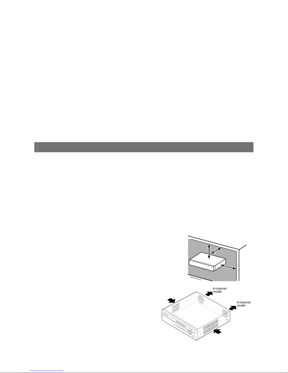
Place this product horizontally on a level surface.
Do not place this product in an upright position. When stacking multiple recorders,
clear a space of more than 5 cm from both sides, the top, the bottom and the rear
of them.
Heat dissipation
Refer to the following to prevent fire and malfunction of this
product.
• Do not bock the ventilation openings in the cover to prevent
this product from overheating. Maintain this product
periodically to prevent dust from blocking openings.
• A lifetime of cooling fans is limited by use. It is recommended
to replace them after approx. 30 000 hours of operation.
Contact your dealer for replacement of the cooling fans.
• Clear a space of more than 5 cm from both sides, the top and
the rear of this product.
More than
5 cm
More than
5 cm
More than
5 cm
7
Avoid placing the unit near noise sources
If the cables are placed near noise sources such as fluorescent lamps, noises may be produced. In this case,
rewire avoiding the noise sources, or move this product to a place far from the source.
Power source
A grounding connection must be made before connecting the power plug of this product to the main power
supply. When disconnecting the grounding wire, make sure that the power plug of this product is
disconnected from the main power supply.
How to mount the power cord
Insert the power cord to the limit on the recorder.
Be sure to connect the power cord via any of the following breaking devices:
• Connect the power cord via a power supply control unit.
• Install the product near a power outlet, and connect the power cord via the power plug.
• Connect the power cord to the breaker with contact gap of 3.0 mm or more of a distribution board. The breaker
shall be able to shut down all the poles of the main power supply except the ground protective conductor.
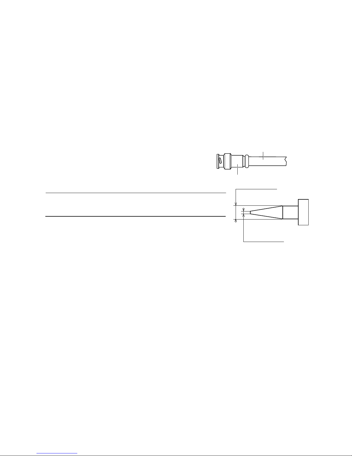
For BNC cable connection
Use only the recommended plug below when connecting the BNC
plug to the connectors on the rear panel of the recorder.
Applicable plug: BS CECC2212: 1981
* Suffixes attached to the standards may be updated.
Tip dimensions inside the recommended BNC plug
Important:
• A compatible plug shall be used. Failure to observe this may cause trouble such
as poor contact. At worst, the connector of this product may be damaged.
Avoid placing receptacles that contain liquids such as water near this product.
If liquid spills onto this product, it may cause fire or an electric shock.
Plug
BNC cable (locally procured)
ø1.32 mm - ø1.37 mm
ø0.13 mm -ø0.69 mm

8
Table of Contents
Chapter 1 -- Introduction ..............................................................................................................................12
Features......................................................................................................................................................12
Technical Overview...................................................................................................................................12
Chapter 2 -- Installation ................................................................................................................................14
Package Contents .....................................................................................................................................14
Required Installation Tools ......................................................................................................................15
Video Input Connector [VIDEO IN 1 to 8 or 4].....................................................................................15
Video Output Connector [VIDEO OUT 1 to 8 or 4]..............................................................................15
RS485 Terminal [485 A / B] ................................................................................................................16
Alarm Input / Output Terminal [ALARM IN] / [ALARM OUT] ..............................................................16
Network Port
[10/100BASE-T]
............................................................................................................16
Serial Port [SERIAL]............................................................................................................................16
Audio Input / Output Connector [AUDIO IN 1 to 4] / [AUDIO OUT] (RCA pin jack) ............................16
Monitor Output Connector [MON 1] / [MON 2 (SPOT)] / [MON 3 (VGA)] ..........................................17
Factory Reset Switch ...........................................................................................................................17
Power Inlet [AC IN]..............................................................................................................................17
Chapter 3 -- Configuration ...........................................................................................................................18
Front Panel Controls.................................................................................................................................18
Camera Buttons [1] to [8] or [4]...........................................................................................................18
HDD Indicator [HDD]...........................................................................................................................19
Alarm Indicator [ALARM] ....................................................................................................................19
Link Indicator [LINK]............................................................................................................................19
Copy Indicator [COPY]........................................................................................................................19
Operate Indicator [OPERATE] ............................................................................................................19
Mouse / Copy Port [MOUSE/COPY] ..................................................................................................19
Arrow Buttons [ ] / [ ] / [ ] / [ ] ...................................................................................................19
Play / Pause Button [ ]......................................................................................................................19
Menu / PTZ Button ([MENU] or [PTZ]) ...............................................................................................19
Playback / Edit Group Button ([PLAYBACK] or [EDIT GROUP]).......................................................20
Next Group / Sequence Button ([NEXT GROUP] or [SEQ])..............................................................20
Multiscreen / Spot Button ([MULTISCREEN] or [SPOT])...................................................................20
EL-Zoom / Return Button ([EL-ZOOM] or [RET]) ...............................................................................20
Copy / Preset View Button ([COPY] or [PRESET VIEW])..................................................................20
Alarm / Preset Set Button ([ALARM] or [PRESET SET]) ...................................................................20
Panic Button [PANIC]..........................................................................................................................20
Turning on the Power ...............................................................................................................................21
Initial Unit Setup ........................................................................................................................................21
Setup Screen..............................................................................................................................................22
System Setup.............................................................................................................................................22
Information ...............................................................................................................................................23
Date/Time ................................................................................................................................................25
Storage.....................................................................................................................................................26
User..........................................................................................................................................................27
Shutdown .................................................................................................................................................29
Network Setup ...........................................................................................................................................29
Network ....................................................................................................................................................29
Mail...........................................................................................................................................................31
Devices Setup............................................................................................................................................32
Camera ....................................................................................................................................................32
Audio ........................................................................................................................................................33
Alarm-Out.................................................................................................................................................34
Display .....................................................................................................................................................35
Recording Setup........................................................................................................................................37
Record......................................................................................................................................................37

9
Schedule ..................................................................................................................................................39
Pre-Event .................................................................................................................................................40
Event Setup................................................................................................................................................41
Alarm-In....................................................................................................................................................41
Motion Detection......................................................................................................................................43
Video Loss ...............................................................................................................................................45
Video Blind...............................................................................................................................................46
System Event...........................................................................................................................................48
Event Status.............................................................................................................................................49
Chapter 4 -- Operation ..................................................................................................................................50
Turning on the Power ...............................................................................................................................50
Live Monitoring..........................................................................................................................................50
Live Monitoring Menu ..............................................................................................................................51
Edit Group Mode......................................................................................................................................52
EL-Zoom Mode ........................................................................................................................................52
PTZ Mode ................................................................................................................................................52
Event Monitoring......................................................................................................................................54
Covert Camera.........................................................................................................................................54
Spot Monitoring........................................................................................................................................54
Using a Mouse ...........................................................................................................................................55
Recording Video ........................................................................................................................................56
Panic Recording.......................................................................................................................................56
Recording Audio........................................................................................................................................56
Playing Recorded Video ...........................................................................................................................56
Searching Video ........................................................................................................................................ 58
Search Menu............................................................................................................................................58
Event Log Search ....................................................................................................................................60
Record Table Search...............................................................................................................................61
Calendar Search......................................................................................................................................62
Motion Search..........................................................................................................................................62
Clip Copy..................................................................................................................................................63
Appendix........................................................................................................................................................66
Display Setup Menu of Camera ...............................................................................................................66
System requirements for a PC.................................................................................................................66
Clip Player ..................................................................................................................................................67
Web Browser..............................................................................................................................................69
Watch Mode ...............................................................................................................................................70
Search Mode ..............................................................................................................................................72
Time Overlap..............................................................................................................................................74
Pin Outs ......................................................................................................................................................75
Alarm Input / Output.................................................................................................................................75
RS485 ......................................................................................................................................................75
Map of Screens ..........................................................................................................................................76
Recording Duration (for reference purpose only) ................................................................................. 77
System Log Notices ..................................................................................................................................78
Error Code Notices....................................................................................................................................79
Troubleshooting ........................................................................................................................................80
Specifications ............................................................................................................................................82

10
List of Illustrations
Figure 1 : Typical installation...........................................................................................................................13
Figure 2 : 8-channel model rear panel............................................................................................................15
Figure 3 : 4-channel model rear panel............................................................................................................15
Figure 4 : 8-channel model front panel ...........................................................................................................18
Figure 5 : 4-channel model front panel ...........................................................................................................18
Figure 6 : Login screen ...................................................................................................................................21
Figure 7 : Logout screen .................................................................................................................................21
Figure 8 : Setup screen...................................................................................................................................22
Figure 9 : Virtual Keyboard screen .................................................................................................................22
Figure 10 : System menu................................................................................................................................22
Figure 11 : Information screen ........................................................................................................................23
Figure 12 : Upgrade screen ............................................................................................................................23
Figure 13 : Setup Import screen .....................................................................................................................23
Figure 14 : Setup Export screen .....................................................................................................................24
Figure 15 : System Log screen .......................................................................................................................24
Figure 16 : System Log Export screen ...........................................................................................................24
Figure 17 : Date/Time - Date/Time screen .....................................................................................................25
Figure 18 : Date/Time - Holiday screen ..........................................................................................................25
Figure 19 : Date/Time - Time Sync. screen. ...................................................................................................26
Figure 20 : Storage - Information screen ........................................................................................................26
Figure 21 : Internal 1(Storage Format) screen ...............................................................................................26
Figure 22 : Internal 1 (Storage Information) screen........................................................................................27
Figure 23 : Storage - Status screen ................................................................................................................27
Figure 24 : User screen...................................................................................................................................27
Figure 25 : New Group screen........................................................................................................................28
Figure 26 : New User (User Information) screen............................................................................................28
Figure 27 : Shutdown screen ..........................................................................................................................29
Figure 28 : Network menu...............................................................................................................................29
Figure 29 : Network - Network screen ............................................................................................................29
Figure 30 : Network - LAN (Manual) screen ...................................................................................................30
Figure 31 : Port Number Setup screen ...........................................................................................................30
Figure 32 : Network - LAN (DHCP) screen.....................................................................................................31
Figure 33 : Network - Web Browser screen....................................................................................................31
Figure 34 : Mail screen....................................................................................................................................31
Figure 35 : Authentication screen ...................................................................................................................32
Figure 36 : Devices menu ...............................................................................................................................32
Figure 37 : Camera - Settings screen.............................................................................................................32
Figure 38 : Camera - PTZ screen ...................................................................................................................33
Figure 39 : PTZ device list ..............................................................................................................................33
Figure 40 : Port Setup screen .........................................................................................................................33
Figure 41 : Audio screen .................................................................................................................................33
Figure 42 : Alarm-Out - Settings screen .........................................................................................................34
Figure 43 : Alarm-Out - Schedule screen .......................................................................................................34
Figure 44 : Display - OSD screen ...................................................................................................................35
Figure 45 : OSD Margin screen ......................................................................................................................35
Figure 46 : Display - Main Monitor screen ......................................................................................................35
Figure 47 : Display - Spot Monitor screen ......................................................................................................36
Figure 48 : Display - VGA screen ...................................................................................................................36
Figure 49 : VGA monitor position screen........................................................................................................37
Figure 50 : Record menu ................................................................................................................................37
Figure 51 : Record - Settings screen ..............................................................................................................37
Figure 52 : Record - Panic Record screen .....................................................................................................38
Figure 53 : Schedule screen ...........................................................................................................................39
Figure 54 : Schedule - Settings (Advanced Mode) setup screen...................................................................40
Figure 55 : Default (Schedule - Advanced Mode) screen ..............................................................................40
Figure 56 : Pre-Event screen ..........................................................................................................................41

11
Figure 57 : Event menu..................................................................................................................................41
Figure 58 : Alarm-In - Settings screen ............................................................................................................41
Figure 59 : Alarm-In - Actions 1 screen ..........................................................................................................42
Figure 60 : Alarm-In Notify screen ..................................................................................................................42
Figure 61 : Alarm-In - Actions 2 screen ..........................................................................................................42
Figure 62 : Motion Detection - Settings screen ..............................................................................................43
Figure 63 : Motion Detection Sensitivity screen .............................................................................................43
Figure 64 : Motion Detection Min. Blocks screen ...........................................................................................43
Figure 65 : Motion Detection Zone screen......................................................................................................43
Figure 66 : Motion Detection Zone menu .......................................................................................................44
Figure 67 : Daytime Setup screen ..................................................................................................................44
Figure 68 : Motion Detection - Actions 1 screen.............................................................................................44
Figure 69 : Motion Detection - Actions 2 screen.............................................................................................45
Figure 70 : Video Loss - Settings screen........................................................................................................45
Figure 71 : Video Loss - Actions 1 screen ......................................................................................................45
Figure 72 : Video Loss - Actions 2 screen ......................................................................................................46
Figure 73 : Video Blind - Settings screen .......................................................................................................46
Figure 74 : Video Blind - Sensitivity screen ....................................................................................................46
Figure 75 : Video Blind - Actions 1 screen......................................................................................................47
Figure 76 : Video Blind - Actions 2 screen......................................................................................................47
Figure 77 : System Event - Health Check screen...........................................................................................48
Figure 78 : Check Recording screen ..............................................................................................................48
Figure 79 : System Event - Storage screen....................................................................................................48
Figure 80 : System Event - Actions screen.....................................................................................................49
Figure 81 : Event Status - Event Status screen..............................................................................................49
Figure 82 : Live Monitoring menu ...................................................................................................................50
Figure 83 : Sequence pattern .........................................................................................................................51
Figure 84 : Camera menu ...............................................................................................................................51
Figure 85 : PTZ Select Camera menu ............................................................................................................53
Figure 86 : PTZ Preset menu..........................................................................................................................53
Figure 87 : Advanced PTZ menu....................................................................................................................53
Figure 88 : PTZ panel .....................................................................................................................................53
Figure 89 : Spot Monitor menu .......................................................................................................................54
Figure 90 : Mouse Display menu ....................................................................................................................55
Figure 91 : Select Playback Camera menu ....................................................................................................56
Figure 92 : Compact View Record Table........................................................................................................57
Figure 93 : Search menu.................................................................................................................................58
Figure 94 : Search menu.................................................................................................................................58
Figure 95 : Go to menu ...................................................................................................................................58
Figure 96 : Go to the Date/Time screen .........................................................................................................58
Figure 97 : Export menu..................................................................................................................................59
Figure 98 : Camera menu ...............................................................................................................................59
Figure 99 : Event Log Search screen .............................................................................................................60
Figure 100 : Event Log Search Option screen ...............................................................................................60
Figure 101 : Record Table Search screen......................................................................................................61
Figure 102 : Search menu ..............................................................................................................................61
Figure 103 : Calendar Search screen.............................................................................................................62
Figure 104 : Motion Search screen.................................................................................................................62
Figure 105 : Motion Search Option screen.....................................................................................................63
Figure 106 : Clip Copy screen ........................................................................................................................64

12
Chapter 1 -- Introduction
Features
Your color digital disk recorder provides recording capabilities for eight camera inputs. It provides
exceptional picture quality in both live and playback modes, and offers the following features:
8 or 4 composite video inputs
WJ-HL208 is 8-channel model
WJ-HL204 is 4-channel model
H.264 codec for efficient digital video recording
Real time recording
200 ips with standard (CIF) resolution (8-channel model)
100 ips with standard (CIF) resolution (4-channel model)
Selectable 4 recording qualities (Very High, High, Standard, Basic)
Selectable 3 recording resolutions (D1, Half-D1, CIF)
Multiple Recording mode (Time-Laps, Pre-Event, Alarm, Motion and Panic)
Multiple Search engine (Date/Time, Calendar, Record table, Event and Motion)
Easy operation with user-friendly GUI (Graphical User Interface) and mouse
4-channel audio recording and 1-channel audio playback
Camera control via RS-485 (Panasonic and Pelco-D protocol supported)
Continues recording while transmitting to web browser and during playback
Self-diagnostics with automatic notification including HDD S.M.A.R.T. protocol
Equipped with 3 HDD slots
Technical Overview
In addition to replacing both a time-lapse VCR and a multiplexer in a security installation, your recorder has
many features that make it much more powerful and easier to use than even the most advanced VCR.
The recorder converts analog PAL video to digital images and records them on a hard disk drive. Using a
hard disk drive allows you to access recorded video almost instantaneously; there is no need to rewind tape.
The technology also allows you to view recorded video while the recorder continues recording video.
Digitally recorded video has several advantages over analog video recorded on tape. There is no need to
adjust tracking. You can freeze frames, fast forward, fast reverse, slow forward and slow reverse without
image streaking or tearing. Digital video can be indexed by time or events, and you can instantly view video
after selecting the time or event.
Your recorder can be set up for event or time-lapse recording. You can define times to record, and the
schedule can change for different days of the week and user defined holidays.
13
The recorder can be set up to alert you when the hard disk drive is full, or it can be set to record over the
oldest video once the disk is full.
You can view video and control your recorder remotely by connecting via Ethernet. There is a COPY ports
that can be used to upgrade the system or copy video clips to external flash drives.
Note: This manual covers the 8- and 4-channel digital disk recorders. The recorders are almost
the same specification except for the number of cameras and alarms that can be
connected and the number of cameras that can be displayed. In the 4-channel model, a
part of function is not equipped.
For simplicity, the illustrations and descriptions in this manual refer to the 8-channel
model.
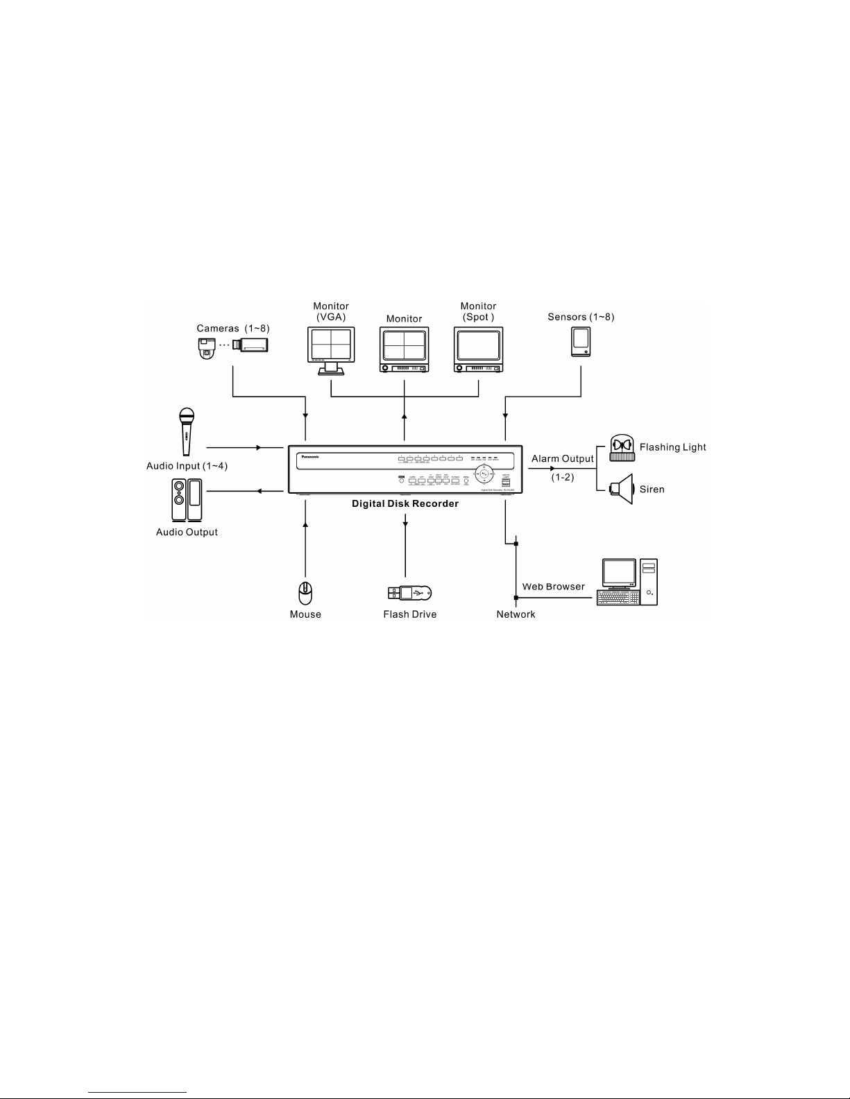
Figure 1 : Typical installation

14
Chapter 2 -- Installation
Package Contents
The package contains the following:
Digital Disk Recorder
Power Cord ×2
Operating Instructions (This Document)
Assembly Screws for Adding Hard Disk Drives
Serial ATA cable ×2
HDD Fixing Screw ×12 (including 4 as spares)
CD-ROM ×1
The CD-ROM contains the regulations documents and important safety instructions (PDFs) written
in the following language; French, German, Spanish, Italian and Russian.
Adobe® Reader® is required to read the PDF files on the provided CD-ROM. When Adobe®
Reader
®
is not installed on the PC, download the latest Adobe® Reader® from the Adobe web site
and install it.
15
Required Installation Tools
No special tools are required to install the recorder. Refer to the installation manuals for the other items that
make up part of your system.
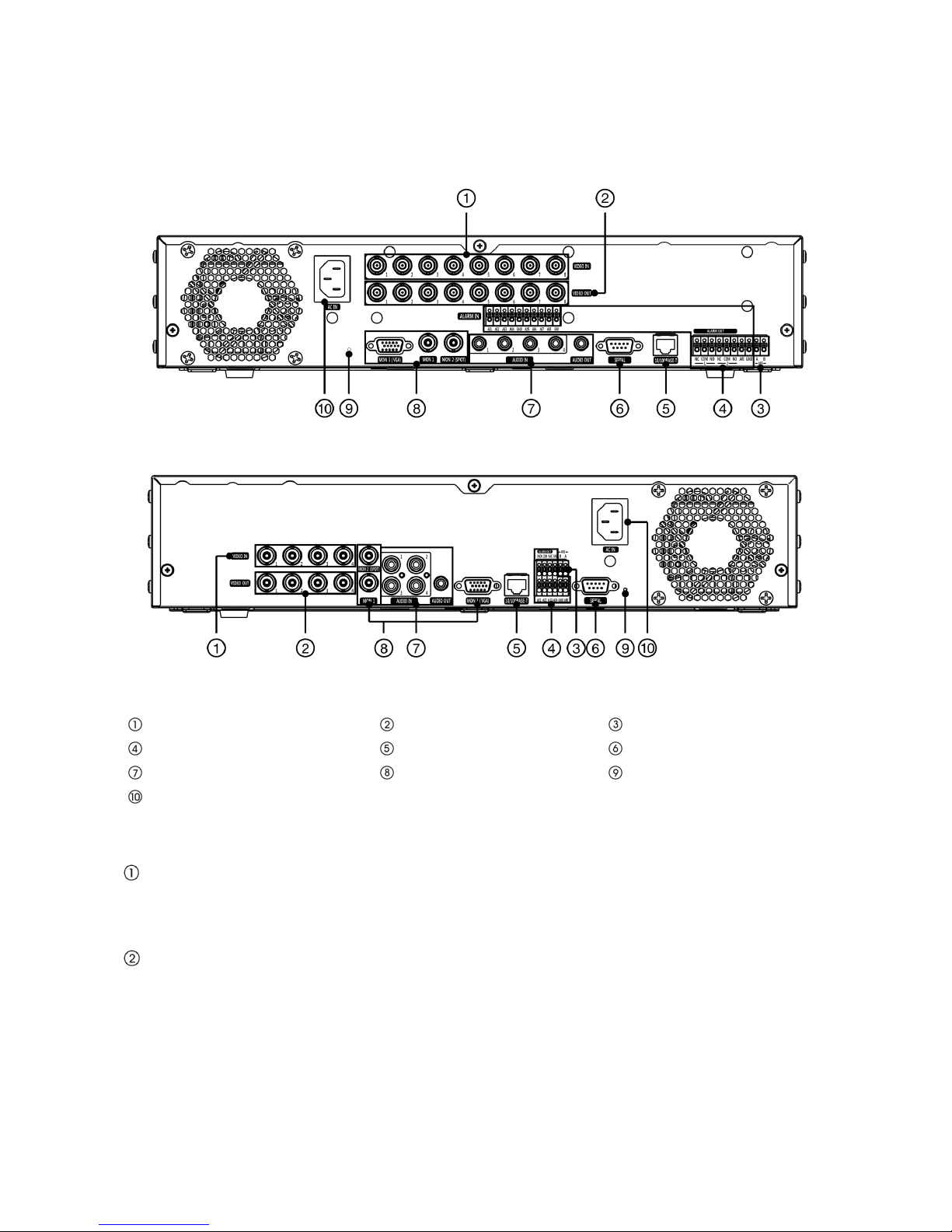
Figure 2 : 8-channel model rear panel
Figure 3 : 4-channel model rear panel
Video Input Connector
Video Output Connector
RS485 Terminal
Alarm Input / Output Terminal
Network Port
Serial Port
Audio Input / Output Connector
Monitor Output Connector
Factory Reset Switch
Power Inlet
Your recorder can be used with PAL equipment.
Video Input Connector [VIDEO IN 1 to 8 or 4]
Connect the coaxial cables from the video sources to the Video Input BNC connectors.
The 4-channel model has 4 Video Input BNC connectors [VIDEO IN 1 to 4].
Video Output Connector [VIDEO OUT 1 to 8 or 4]
If you would like to connect your video source to another device, you can use the Video Output BNC
connectors.
The 4-channel model has 4 Video Output BNC connectors [VIDEO Out 1 to 4].
Note: The Video Output BNC connectors are auto terminated. Do NOT connect a cable to the
Video Output BNC connectors unless it is connected to a terminated device because it will
cause poor quality video.

16
RS485 Terminal [485 A / B]
The recorder can control PTZ (Pan/Tilt/Zoom) cameras using RS485 half-duplex serial communications
signals. Connect RX+/TX+ and RX-/ TX- of the control system to the A and B (respectively) of the recorder.
See “Chapter 3 -- Configuration” and the PTZ camera’s manual for configuring the RS485 connection.
Alarm Input / Output Terminal [ALARM IN] / [ALARM OUT]
Note: To make connections on the Alarm Terminal Strip, press and hold the button and insert the
wire in the hole below the button. After releasing the button, tug gently on the wire to
make certain it is connected. To disconnect a wire, press and hold the button above the
wire and pull out the wire.
The 4-Channel model has 4 Alarm Input Terminals [AI1] to [AI4].
[AI1] to [AI8] or [AI4] (Alarm Input) : You can use external devices to signal the recorder to react to events.
Mechanical or electrical switches can be wired to the [AI] (Alarm Input) and [GND] (Ground) terminals. The
threshold voltage of electrical switches for [NC] (Normally Closed) is above 2.4 V and for [NO] (Normally
Open) is below 0.3 V, and should be stable at least 0.5 seconds to be detected. The voltage range of alarm
input is from 0 V to 5 V. See “Chapter 3 -- Configuration” for configuring alarm input.
[GND] (Ground) : Connect the ground side of the Alarm input and/or alarm output to the GND terminal.
Note: All the terminals marked GND are common.
[NC]/[NO] (Relay Alarm Outputs) : The recorder can activate external devices such as buzzers or lights.
Connect the device to the [COM] (Common) and [NC] (Normally Closed) or [COM] and [NO] (Normally
Open) terminals. [NC]/[NO] is a relay output which sinks 1 A 30 V
peak
(maximum). See “Chapter 3 --
Configuration” for configuring alarm output.
[ARI] (Alarm Reset In) : An external signal to the Alarm Reset In can be used to reset both the Alarm Out
signal and the recorder’s internal buzzer. Mechanical or electrical switches can be wired to the [ARI] (Alarm
Reset In) and [GND] (Ground) terminals. The threshold voltage is below 0.3 V and should be stable at least
0.5 seconds to be detected. Connect the wires to the [ARI] (Alarm Reset In) and [GND] (Ground) terminals.
Network Port
[10/100BASE-T]
The recorder can be networked using the 10/100Mbps Ethernet connector. Connect a Cat5 cable with an
RJ-45 jack to the recorder connector. The recorder can be networked with a computer for remote monitoring,
searching. See “Chapter 3 -- Configuration” for configuring the Ethernet connections.
Important: The network port is not designed to be connected directly with cable or wire
intended for outdoor use.
Please keep away a cat5 cable and other cable which has a lot of noises,
lightning and surge.
Serial Port [SERIAL]
Reserved.
Audio Input / Output Connector [AUDIO IN 1 to 4] / [AUDIO OUT] (RCA pin jack)
Your recorder can record audio from up to four sources. Connect the audio sources to the Audio Input
Connectors 1 to 4 as needed using RCA jacks.
Connect the Audio Output Connector to your amplifier.
Note: It is the user’s responsibility to determine if local laws and regulations permit recording
audio.
The recorder does not have amplified audio output, so you will need a speaker with an
amplifier. The recorder does not have a pre-amplifier for audio input, so the audio input
should be from an amplified source, not directly from a microphone.

17
Monitor Output Connector [MON 1] / [MON 2 (SPOT)] / [MON 3 (VGA)]
A [MON 3 (VGA)] connector is provided so that you can use a standard, multi-sync computer monitor as your
main monitor. Use the cable supplied with your monitor to connect it to the recorder.
Connect the main monitor to the [MON 1] connector. Connect the spot monitor to the [MON 2 (SPOT)]
connector as needed.
Note: The [MON 3 (VGA)] and [MON 1] (BNC) connectors may be connected to individual
monitors for simultaneous operation.
Please keep away cables and other cables which have a lot of noises, lightning and surge.
Factory Reset Switch
The recorder has a Factory Reset switch to the left of the [MON 3 (VGA)] connector (4-channel model : the
right of the Serial Port) on the rear panel. This switch will only be used on the rare occasions that you want to
return all the settings to the original factory settings.
Important: When using the Factory Reset Switch, you will lose any settings you have
saved. (Excluded camera titles you can change in the Web Browser.)
To reset the unit, you will need a straightened paperclip:
1. Turn the recorder off.
2. Turn it on again with insert the straightened paperclip into the unlabeled hole in the left of the [MON 3
(VGA)] connector (or the right of the Serial Port : 4-channel model).
Note: Continue inserting until the internal buzzer starts to sound. (approximately 30 seconds
after turned on)
3. Release the reset switch. All of the recorder’s settings are now at the original settings it had when it
left the factory.
Power Inlet [AC IN]
Connect the provided AC power cord to the recorder and then to a wall outlet.
WARNING: ROUTE POWER CORDS SO THAT THEY ARE NOT A TRIPPING HAZARD.
MAKE CERTAIN THE POWER CORD WILL NOT BE PINCHED OR ABRADED
BY FURNITURE. DO NOT INSTALL POWER CORDS UNDER RUGS OR
CARPET.
THE POWER CORD HAS A GROUNDING PIN. IF YOUR POWER OUTLET
DOES NOT HAVE A GROUNDING PIN RECEPTACLE, DO NOT MODIFY THE
PLUG. DO NOT OVERLOAD THE CIRCUIT BY PLUGGING TOO MANY
DEVICES IN TO ONE CIRCUIT.
Your recorder is now ready to operate. Refer to “Chapter 3 -- Configuration” and “Chapter 4 -- Operation”.
18
Chapter 3 -- Configuration
Note: Your recorder should be completely installed before proceeding. Refer to “Chapter 2 --
Installation”.
Front Panel Controls
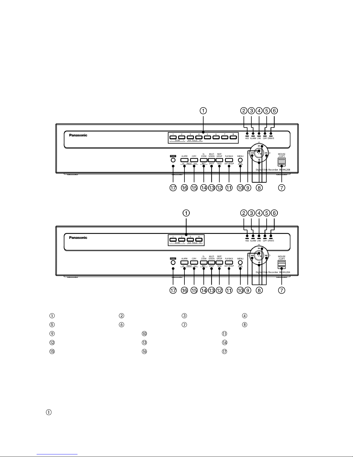
Figure 4 : 8-channel model front panel
Figure 5 : 4-channel model front panel
Camera Buttons HDD Indicator Alarm Indicator Link Indicator
Copy Indicator Operate Indicator Mouse / Copy Port Arrow Buttons
Play / Pause Button Menu / PTZ Button Playback / Edit Group Button
Next Group / Sequence Button Multiscreen / Spot Button EL-Zoom / Return Button
Copy / Preset View Button Alarm / Preset Set Button Panic Button
The front panel looks and operates much like a VCR combined with a multiplexer. Many of the buttons have
multiple functions. The following describes each button and control. Take a few minutes to review the
descriptions. You will use these to initially set up your recorder and for daily operations.
Note: You can also use a USB mouse (not supplied) to navigate through the screens and menus
much like you would on a computer.
Camera Buttons [1] to [8] or [4]
Pressing the individual camera buttons will cause the selected camera to display full screen. Buttons [1] to

19
[8] or [4] ( : 4-channel model) are also used to enter passwords.
In the PTZ mode, pressing the button [1] ([ZOOM -]) zooms out the screen and the button [2] ([ZOOM +])
zooms in the screen, pressing the button [3] ([FOCUS NEAR]) focuses near and button [4] ([FOCUS FAR])
focuses far.
HDD Indicator [HDD]
The HDD Indicator flickers when the recorder is recording or searching video on the hard disk drive.
Alarm Indicator [ALARM]
The Alarm Indicator is lit when alarm output or internal buzzer is activated.
Link Indicator [LINK]
The Link Indicator is lit when the unit is connected to a network via Ethernet.
Copy Indicator [COPY]
The Copy Indicator is lit when the recorder is copying video clips.
Operate Indicator [OPERATE]
The Operate Indicator is lit when the unit is On.
Mouse / Copy Port [MOUSE/COPY]
The [MOUSE/COPY] ports on the front panel are provided to connect flash drives for video clip copying or
system upgrades. Position external flash drive close enough to the recorder so that you can make the cable
connections, usually less than 1.8 m.
A USB mouse (not supplied) can be connected to one of the ports. You can use the mouse to navigate
through the screens and menus much like you would on a computer.
Arrow Buttons [ ] / [ ] / [ ] / [ ]
These buttons are used to navigate through menus and GUI. You can also use them to change numbers by
highlighting a number in the menu and using the Up and Down arrow buttons to increase or decrease the
number’s value.
These buttons are also used to control Pan and Tilt when in the PTZ mode. When in the PIP display format,
pressing the Up and Down arrow buttons moves the position of the small screen counter-clockwise and
clockwise, and pressing the Left and Right buttons changes the PIP screen size.
In the playback mode, pressing the button plays video backward at high speed. Pressing the button
again toggles the playback speed from “
”, “ ” and “ ”. The screen displays “ ”, “ ” and
“
” respectively. Pressing the button plays video forward at high speed. Pressing the button again
toggles the playback speed from “
”, “ ” and “ ”. The screen displays “ ”, “ ” and “ ”
respectively. When in the pause mode, pressing the
button moves to the next image and pressing the
button moves to the previous image.
Play / Pause Button [ ]
In the live monitoring mode, pressing the
button freezes the current screen and the screen displays
icon. When in the playback mode, pressing the
button plays back images at regular speed or pauses
playing video.
Pressing the button selects a highlighted item or completes an entry that you have made during system
setup.
Menu / PTZ Button ([MENU] or [PTZ])
Pressing the [MENU] button enters the Setup screen. You will need to enter the authorized user and

20
password to access Setup. Pressing the button also closes the current menu or setup dialog box. In the
Playback mode, pressing the button displays the Search menu.
Pressing and holding the button for three seconds or longer displays the PTZ camera menu. Selecting
cameras from the menu by using the arrow buttons and the
(Play/Pause) button, you can enter the PTZ
mode and can control configured cameras properly.
Playback / Edit Group Button ([PLAYBACK] or [EDIT GROUP])
Pressing the [PLAYBACK] button enters the playback mode, and pressing the button again exits the
playback mode. When entering the playback mode, video is paused. Pressing the (Play/Pause) button
plays back video at regular speed. The screen displays “” when the recorder is in the Pause mode and the
screen displays “” when the recorder is playing back video.
When in one of the multi-view formats, pressing this button enters the Triplex mode. The recorder supports
the Triplex function: monitoring, recording and playing back at the same time.
Pressing and holding the [EDIT GROUP] button for three seconds or longer enters the Edit Group mode.
The yellow outline surrounding the video indicates the active channel, and pressing the arrow buttons moves
the active channel. Pressing the desired camera button in the active channel edits the Group and displays
the video of selected camera. Pressing the
(Play/Pause) button exits the Edit Group mode. Selecting
“Exit Group Edit” in the Edit Group menu displayed when pressing the [MENU/PTZ] button also exits the Edit
Group mode.
Next Group / Sequence Button ([NEXT GROUP] or [SEQ])
When in the live mode, pressing the [NEXT GROUP] button changes the screen from the current camera
group to the next camera group, and the screen displays the page number. (The 4-channel model’s
multi-screen is excluded.)
Pressing and holding the [SEQ] button for three seconds or longer displays live channels sequentially.
Multiscreen / Spot Button ([MULTISCREEN] or [SPOT])
Pressing the [MULTISCREEN] button toggles between different display formats. The available formats are:
PIP, 2x2, and 3x3(only 8-channel model).
Pressing and holding the [SPOT] button for three seconds or longer allows you to select which cameras will
display on the Spot monitor.
EL-Zoom / Return Button ([EL-ZOOM] or [RET])
Pressing the [EL-ZOOM] button zooms digitally in the current image in double on the screen. You can use
the arrow buttons to move the rectangle to another area. Pressing the
(Play/Pause) button zooms in the
image in rectangle.
Pressing the [RET] button allows you to return to the previous menu when you are operating the camera
setup menu in the PTZ mode.
Copy / Preset View Button ([COPY] or [PRESET VIEW])
Pressing the [COPY] button allows you to copy video clips.
The [PRESET VIEW] button is used to load a View Preset in the PTZ mode.
Alarm / Preset Set Button ([ALARM] or [PRESET SET])
The [ALARM] button has two functions. First, it will reset the recorder’s outputs including the internal buzzer
during an alarm. Second, it will display the event log when you are in the live protected. The [PRESET SET]
button is used to save Presets in the PTZ mode.
Panic Button [PANIC]
Pressing the [PANIC] button starts panic recoding of all camera channels, and displays “ ” on the screen.
Pressing the button again will stop panic recording.
21
Turning on the Power
Connecting the power cord to the recorder turns on the unit. The Operate Indicator will light and initializing
will start. While the recorder is initializing, the front panel indicators (except the Operate Indicator) will blink.
The unit takes approximately 60 seconds to initialize.
Initial Unit Setup
Before using your recorder for the first time, you will want to establish the initial settings. This includes items
such as time and date, display language, camera, record mode, network and password. Your recorder can
be set up using various screens and dialog boxes.
Throughout the screens you will see “
”. Highlighting the “ ” and pressing the button gives you the
opportunity to reset that screen to its default settings.
Press the [MENU] button or move the mouse pointer to the top of the screen and then select “
”
(Login) in
the Live Monitoring menu
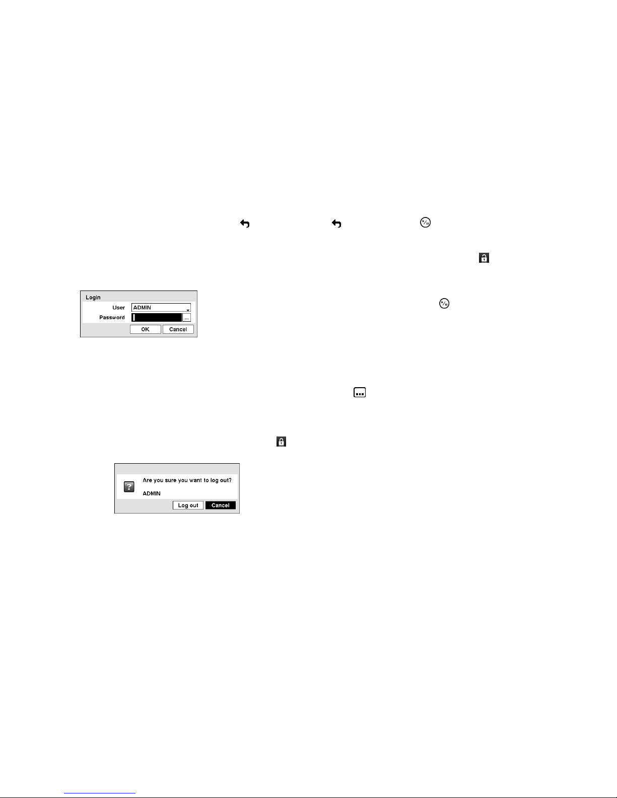
to enter the setup screens. The Login screen appears.
Select a User and enter the password by pressing the appropriate
combination of Camera number buttons and then the
button. Enter the
password (default:1234) when logging in the “ADMIN” user (default) for the
first time.
Figure 6 : Login screen
Note: To assure the secure management of the system, changing the password from the default
setting is strongly recommended.
If you cannot use the front panel buttons, click the button using the mouse to enter a
password, and the virtual keyboard displays. See instructions below for using the virtual
keyboard.
To log the user out of the system, press the [
MENU] button or move the mouse pointer to the
top of the screen and then select “” (Logout) in the Live Monitoring menu. The Logout
screen displays asking you to confirm whether or not you want to log out the current user.
Figure 7 : Logout screen
22
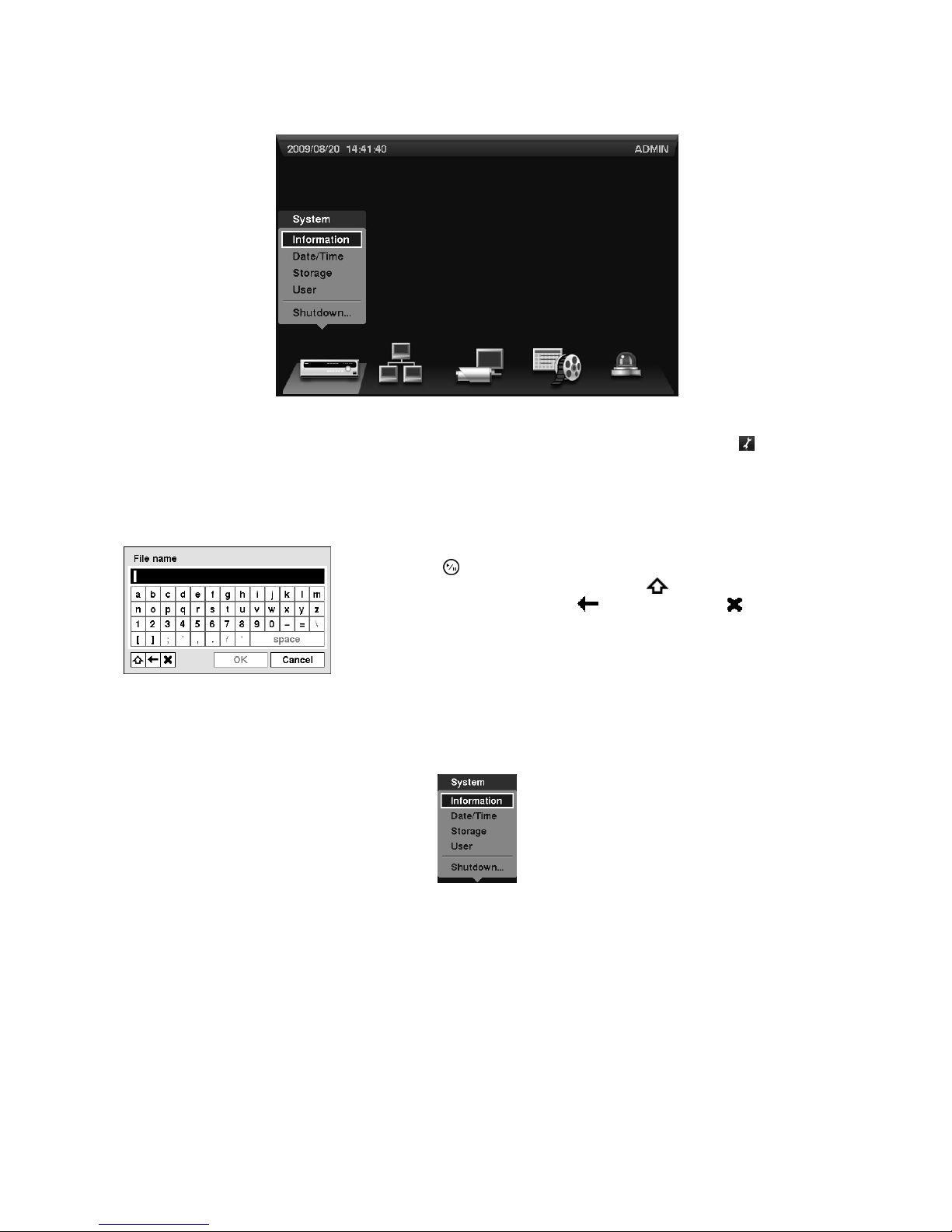
Setup Screen
Figure 8 : Setup screen
Press the [MENU] button or move the mouse pointer to the top of the screen and then select “
” (Setup) in
the Live Monitoring menu to enter the setup screen.
While setting up the recorder, there will be many opportunities to enter names and titles. When making these
entries, a Virtual Keyboard will appear.
Use the arrow keys to highlight the character you want in the name or title
and press the
button. That character appears in the title bar and the
cursor moves to the next position. Pressing “
” toggles between the
upper and lower case keyboards, “
” backspaces, and “ ” deletes
entered characters. You can use up to 31 characters including spaces in
your title.
Figure 9 : Virtual Keyboard screen
System Setup
Figure 10 : System menu
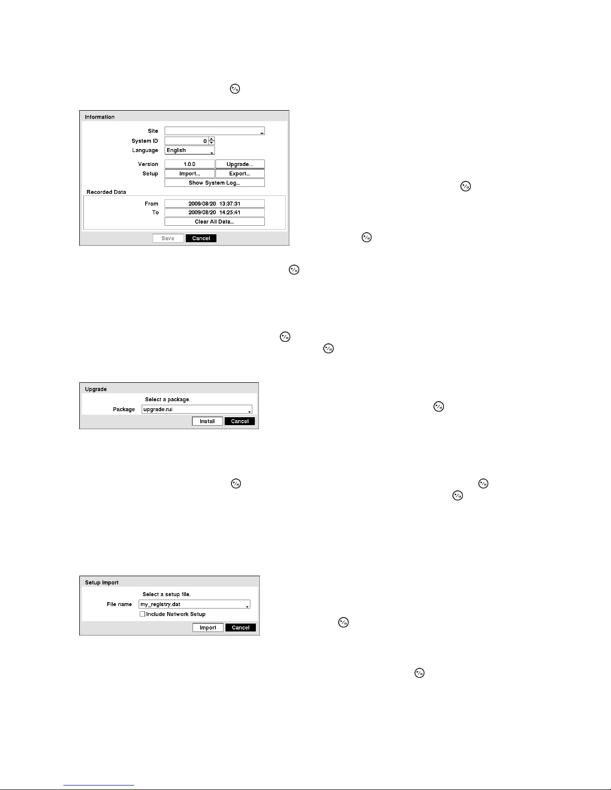
23
Information
Highlight Information and press the
button. The Information screen appears.
In the “Information” screen, you can name the site
location, assign a System ID number, select the
language the screens are displayed in, display
software version number, upgrade the software, show
the System Log, display recorded time data, and clear
all data.
Highlight the “Site” box and press the button. A
virtual keyboard appears that you can use to enter a
Site Name.
Once you have entered your site name, highlight “OK”
and press the
button.
Figure 11 : Information screen
Highlight the box beside System ID and press the button. Change the number by highlighting it and using
the Up and Down arrow buttons to increase and decrease the number from 0 to 99.
Note: The System ID number is used to identify the unit when it is connected with cameras
through the RS485 port.
Highlight the box beside “Language” and press
button. A drop-down menu displays the available
languages. Highlight the desired language and press the
button.
The box beside “Version” displays the software version of the recorder.
To upgrade the software, connect a USB flash drive
containing the upgrade package file to the recorder.
Highlight “Upgrade…” and press the button. The
“Upgrade” screen appears.
Figure 12 : Upgrade screen
The screen displays the upgrade package file names that are available. The “.rui” indicates that the file is for
software upgrades.
Select the desired file and press the button. Highlighting the “Install” button and pressing the button will
install the selected software package. Highlighting the “Cancel” button and pressing the
button will close
the window without upgrading the software. If the upgrade package file is not installed on the recorder
properly, you will get an error message. The system restarts automatically after completing the upgrade.
Important: The USB flash drive must be FAT16 or FAT32 format. The recommended
flash drive is USB 2.0 type.
You can import saved recorder settings or export the current
recorder settings. To import saved recorder settings,
connect the USB flash drive containing the setup file (.dat) to
the recorder. Highlight “Import…” on the Information screen
and press the
button.
Figure 13 : Setup Import screen
Select the desired setup file and press the “Import” button to import the selected settings and change the
recorder settings accordingly. Highlight “Include Network Setup” and press the
button to toggle between
On and Off. When set to Off, the network settings will not be changed.
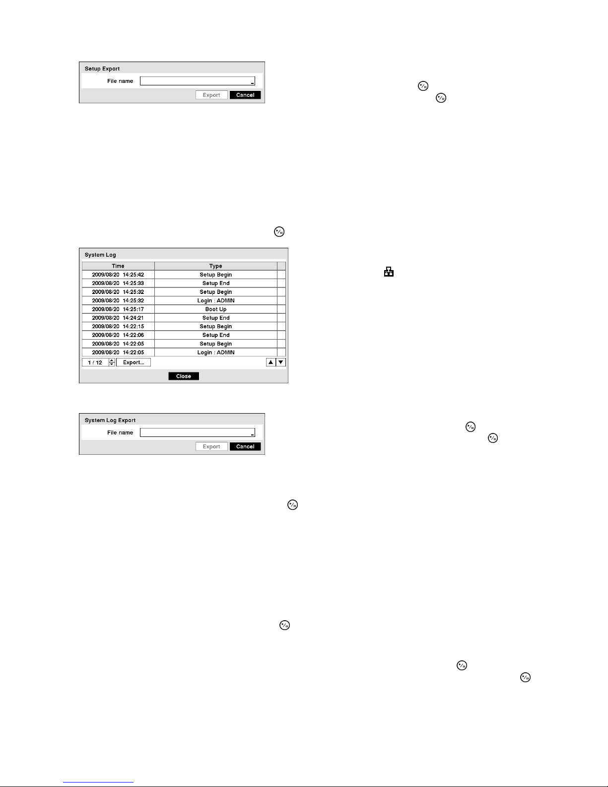
24
To export the current recorder settings, connect the USB
flash drive to the recorder. Highlight “Export…” on the
Information screen and press the
button. Highlight the
box beside “File name” and press the
button.
Figure 14 : Setup Export screen
A virtual keyboard allows you to enter the file name. Selecting “Export” will save the current settings in “.dat”
file format on the USB flash drive.
Note: Even after changing the recorder settings by importing saved settings, the time-related
settings (Date/Time, Time Zone and Daylight Saving Time) will NOT be changed.
Important: The USB flash drive must be FAT16 or FAT32 format. The recommended
flash drive is USB 2.0 type.
Highlight “Show System Log…” and press the button to display the System Log.
The “System Log” screen lists system activities (up to
5,000 from the latest) that have occurred along with the
time and date. The
icon will be displayed in the last
column for system activities of the web browser. You
can scroll through the log pages by using the Up and
Down arrows, or you can go directly to a log page by
entering the log page number in the box at the bottom
left of the screen.
Figure 15 : System Log screen
To export the System Log, connect the USB flash drive to the
recorder. Highlight “Export…” and press the button.
Highlight the box beside “File name” and press the
button.
Figure 16 : System Log Export screen
A virtual keyboard allows you to enter the file name. Selecting “Export” will save the System Log in .txt file
format on the USB flash drive.
Highlighting the “Cancel” button and pressing the button will close the window without saving the System
Log.
Note: When opening the saved .txt file, setting to the proper character encoding and using fixed
width fonts will be required to read the file properly.
Important: The USB flash drive must be FAT16 or FAT32 format. The recommended
flash drive is USB 2.0 type.
The box beside “Recorded Data – From / To” displays the time information of recorded data.
Highlighting “Clear All Data…” and pressing the button will clear all video data. You will be asked to verify
that you wish to clear all data before the recorder erases the video data. “Clear All Data…” will not clear the
System Log.
After you are finished with the Information Screen, you can highlight “Save” and press the button to save
the changes and exit the screen. If you do not wish to save the changes, highlight “Cancel” and press the
button to exit the screen.
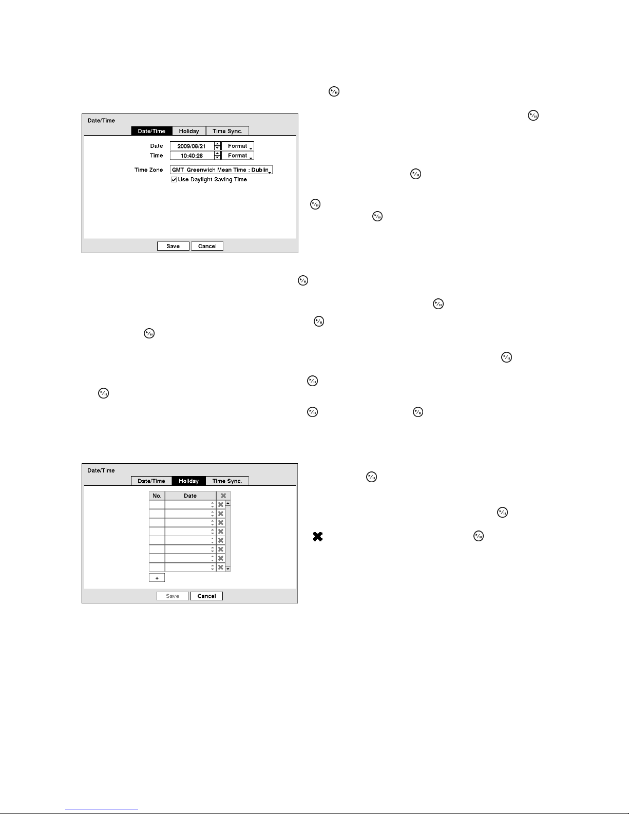
25
Date/Time
Highlight “Date/Time” in the System menu and press the
button. The “Date/Time” setup screen appears.
Highlight the first box beside “Date” and press the
button. The individual sections of the date will highlight.
Use the Up and Down arrow buttons to change the
number. Use the Left and Right arrow buttons to move
between month, date and year. Once you have the
correct date, press the
button.
Highlight the Format box beside “Date” and press the
button. Select from the three available date formats
and press the
button to save your selected format.
Figure 17 : Date/Time - Date/Time screen
Highlight the first box beside “Time” and press the button. The individual sections of the time will highlight.
Use the Up and Down arrow buttons to change the number. Use the Left and Right arrow buttons to move
between hour, minutes and seconds. Once you have the correct time, press the button.
Highlight the Format box beside “Time” and press the button. Select from the three available time formats
and press the
button to save your selected format.
Note:
The clock will not start running until you have highlighted “Save” and pressed the button.
Highlight the box beside “Time Zone” and press the
button. Select your time zone from the list and press
the
button.
Highlight “Use Daylight Saving Time” and press the button. Pressing the button toggles between On
and Off.
Highlight the “Holiday” tab, and the Holiday setup screen appears.
You can set up holidays by highlighting “+” and
pressing the
button. The current date appears.
Highlight the month and day and change them by using
the Up and Down arrow buttons. Press the
button to
add the date. Dates can be deleted by highlighting the
“ ” beside the date and pressing the button.
Figure 18 : Date/Time - Holiday screen
Note: Holidays that do not fall on the same date each year should be updated once the current
year’s holiday has passed.
Highlighting the “Time Sync.” tab causes the Time Sync. screen to display. You can set up time
synchronization between the recorder and standard time servers that are available in most time zones and
countries, or between the recorder and another recorder.
 Loading...