

Page 1
Before attempting to connect or operate this product,
please read these instructions carefully and save this manual for future use.
Extension Unit
Model No.
WJ-HDE510
The serial number of this product may be found on the bottom of the unit.
You should note the serial number of this unit in the space
provided and retain this book as a permanent record of your
purchase to aid identification in the event of theft.
Model No.
Serial No.
WARNING:
• To reduce the risk of fire or electric shock, do not expose this product to rain or moisture.
• All work related to the installation of this product should be made by qualified service personnel or system installers.
• Never look into the DVD-RAM drive of this product. The laser diode incorporated in the drive emits invisible infrared
radiation which is harmful to the eyes.
The lightning flash with arrowhead symbol, within an equilateral triangle, is
intended to alert the user to the presence of uninsulated "dangerous voltage"
within the product's enclosure that may
be of sufficient magnitude to constitute a
risk of electric shock to persons.
The exclamation point within an equilateral triangle is intended to alert the user
to the presence of important operating
and maintenance (servicing) instructions
in the literature accompanying the appliance.
CAUTION: TO REDUCE THE RISK OF ELECTRIC SHOCK,
DO NOT REMOVE COVER (OR BACK).
NO USER-SERVICEABLE PARTS INSIDE.
REFER SERVICING TO QUALIFIED SERVICE PERSONNEL.
CAUTION
RISK OF ELECTRIC SHOCK
DO NOT OPEN
SA 1965
SA 1966
NOTE: This equipment has been tested and found to comply
with the limits for a Class A digital device, pursuant to Part 15
of the FCC Rules. These limits are designed to provide reasonable protection against harmful interference when the
equipment is operated in a commercial environment. This
equipment generates, uses, and can radiate radio frequency
energy and, if not installed and used in accordance with the
instruction manual, may cause harmful interference to radio
communications.
Operation of this equipment in a residential area is likely to
cause harmful interference in which case the user will be
required to correct the interference at his own expense.
FCC Caution: To assure continued compliance, (example use only shielded interface cables when connecting to computer or peripheral devices). Any changes or modifications
not expressly approved by the party responsible for compliance could void the user’s authority to operate this equipment.
For U.S.A
CAUTION:
• Read the label on the bottom of the unit for identification of this product, and the power ratings.
Page 2

-2-
■Precautions
• Do not operate the appliance beyond its specified
temperature, humidity or power source ratings.
Do not use the appliance in an extreme environment
where high temperature or high humidity exists. Use
the appliance at temperatures within +5°C to +45°C
(41°F to 113°F) and a humidity below 90 %.
The input power source for this appliance is 120 V
AC 60 Hz.
• Avoid shock and vibration
Shock or vibration may damage the HDD whether in
operation or not.
Do not move the HDD for 30 seconds right after
turning off the power.
• Pay attention to static electricity
Put your hand on a metallic surface to discharge
static electricity before installation.
Do not touch components on the HDD directly with
your hand.
Always hold the HDD on both sides when installing
it.
• Avoid condensation on the surface of the HDD. Wait
until the dew evaporates in any of the following
cases:
The appliance is moved to a place where the temperature or humidity differs significantly.
The appliance is moved out of an air-conditioned
room.
The appliance is placed in an extremely humid
place.
The appliance is placed in a room where the heater
has just been turned on.
• Consumable parts
Contact your dealer for the replacement of consumables when the time comes.
The built-in hard disk needs replacement after
around 30 000 hours of operation.
The cooling fan also needs replacement after
around 30 000 hours of operation.
• Do not block the ventilation opening or slots on the
cover.
To prevent the appliance from overheating, place it
at least 5 cm (2 inches) away from the wall.
• Do not put your hands into the disk tray. Your fingers might get caught inside the DVD-RAM drive.
• Avoid condensation on the surface of the HDD and
DVD-RAM disk.
• Be sure to install the DVD Extension Unit horizontally.
■General
The WJ-HDE510 is a DVD Extension Unit for connection
with the WJ-HD500 Digital Disk Recorder for copying or
backing up recorded data. The system can be extended by connecting up to 6 extension units in an SCSI
chain while the DVD extension unit containing up to two
HDDs.
The DVD-RAM stands for digital versatile disk-random
access memory. The DVD-RAM can be stored high
capacity data for making a backup.
Available DVD-RAM disks:
Cartridge type I for 9.4 GB (DOUBLE SIDED) NON
REMOVABLE DISC
Cartridge type I for 2.6 GB (SINGLE SIDED) NON
REMOVABLE DISC
Cartridge type II for 4.7 GB (SINGLE SIDED) DISC
REMOVABLE
Cartridge type I for 5.2 GB (DOUBLE SIDED) NON
REMOVABLE DISC
Cartridge type II for 2.6 GB (SINGLE SIDED) DISC
REMOVABLE
*Cartridge type I: Disc cannot be removed from the
cartridge.
*Cartridge type II: Disc can be removed from the
cartridge.
Note: The WJ-HDE510 DVD Extension Unit is designed
for use with Cartridge type I DVD-RAM disks. Type
II DVD-RAM disks can be used only inside the cartridge. Therefore, to use type II DVD-RAM disks, do
not remove the disc from the cartridge.
• Matsushita Electric Industrial Co., Ltd. herewith
declares that it will not be liable in any way for any
loss of data or any other damage, whether direct or
indirect, caused by operation or malfunctioning of
this product. Backup important data to protect it
from possible loss.
• This product is for exclusive use in DVD-RAM drives
according to DVD Specifications ver. 2.0 for
rewritable disc.
• Please note that the WJ-HD500 requires a software
version 1.51 or later for playback the backup data
on the DVD-RAM diskdisk and installing the 80 GB
or more hard disk for extension.
Please contact your nearest dealer or sales office
for version up.
Page 3
-3-
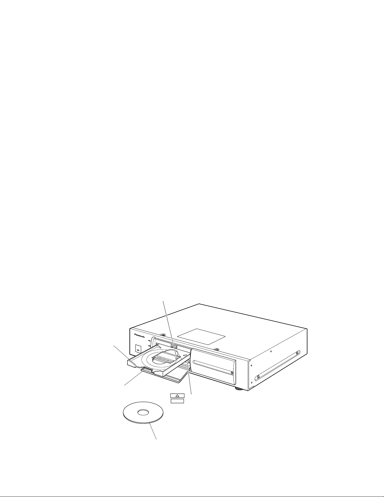
■Cleaning the DVD Drive
The DVD drive needs to be cleaned after prolonged use.
Use the optional cleaning disc as shown below for cleaning the DVD drive.
Panasonic PD Lens Cleaner (Wet-type) LF-K123LCA1
Follow the procedure described below to clean the DVD drive of the DVD Extension Unit.
1. Turn on the power switch located on the rear of the DVD-Extension Unit.
2. Press the DVD-RAM lid to open the lid located on the front of the DVD Extension Unit.
3. Press the OPEN/CLOSE button inside the DVD-RAM drive to slide out the disk tray.
4. Insert the cleaning disc into the tray.
(Refer to the operating instructions of the cleaning disc for details.)
5. Press the OPEN/CLOSE button on the DVD-RAM drive to slide in the tray. Cleaning will start automatically.
6. Press the OPEN/CLOSE button to slide out the tray.
7. Press the OPEN/CLOSE button again to slide in the tray.
8. Close the DVD-RAM lid.
Note: The optimum cleaning frequency differs depending on the usage environment and conditions. It is recommended
though to clean the drive once every one to four months.
Disk tray
DVD-RAM lid
Cleaning disc
BUSY indicator
OPEN/CLOSE button
Handling DVD-RAM disks
• Avoid exposure to direct sunlight.
• Avoid any contact with water.
• Do not place near heat sources such as radiators,
stoves or other units that produce heat.
• Do not touch the DVD-RAM disc recording surface
directly with your hand.
• Do not press, bend or place heavy objects against
the cartridge case.
• Do not store in very dusty areas.
• Do not attach multiple labels one on top of the other
on the DVD-RAM disk, and do not paste over a label
that has been torn off.
• Keep the DVD-RAM disk in the case when not using
it.
• To protect the DVD-RAM data, set the protection to
”Write disable” position.
Page 4
-4-
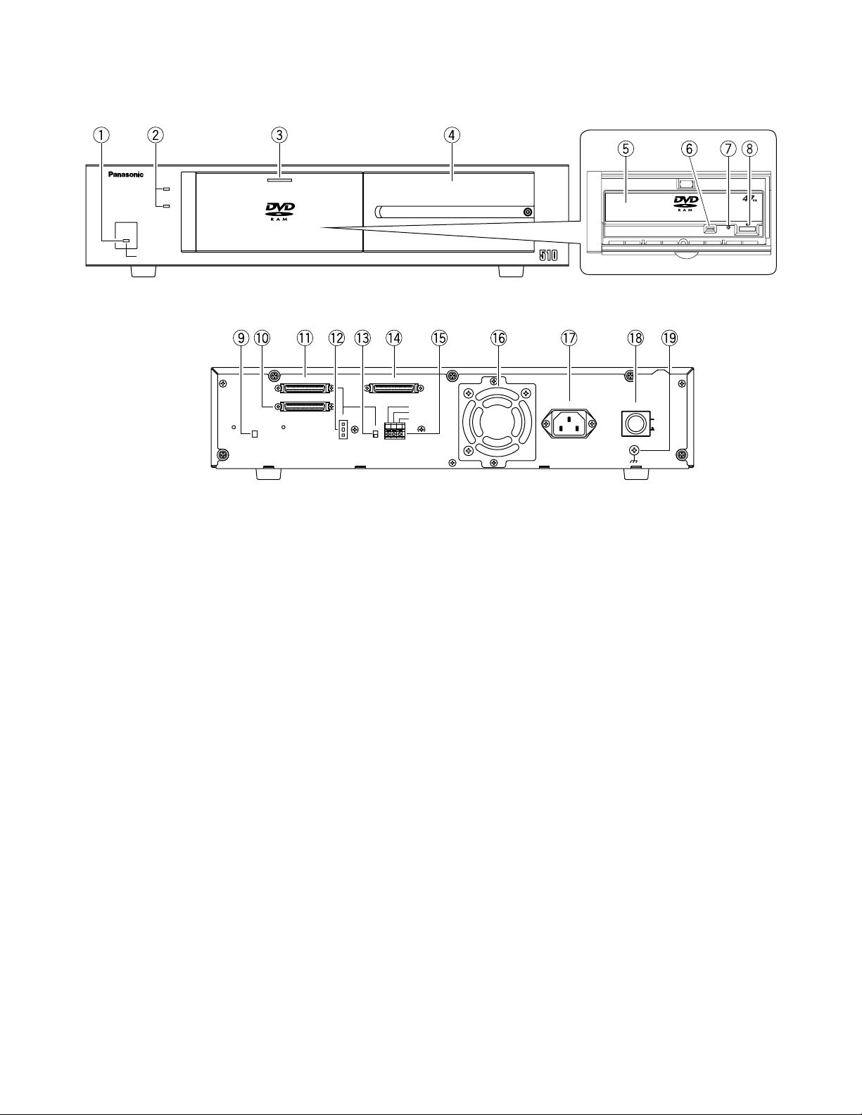
■Appearance
q Operate indicator (OPERATE)
Lights in green while power is supplied to the unit.
Lights in orange when a thermal error is detected
inside the unit.
w HDD indicator (HDD 1) (HDD 2)
Lights in green while the HDD is accessed. Do not
turn off the POWER switch while any of the access
indicators is lit.
e DVD-RAM lid
Protects the DVD-RAM drive from dust. Press this lid
to install the DVD-RAM disk. The DVD-RAM lid normally should be kept closed to prevent dust from
entering the drive.
r HDD lid
Two HDD openings are provided inside the DVD
Extension Unit. Remove this lid to install the HDD.
Replace the lid after installing the HDD.
t DVD-RAM drive (tray)
y Busy indicator
Lights in green when a DVD-RAM is installed in the
DVD Extension Unit.
It changes to orange while the DVD-RAM Drive is
running.
u Eject hole
i Open/Close button
Is used for insertion or removal of the DVD-RAM
disk while the DVD-RAM lid is opened.
o Hard Disk Detection switch (HDD INSTALLED/
NOT INSTALLED)
Detects an optional HDD when one is installed.
!0 SCSI Output connector (EXT OUT)
Connect another Extension Unit with an SCSI cable.
!1 SCSI Input connector (EXT IN)
Connect the WJ-HD500 or another Extension Unit
with an SCSI cable.
!2 SCSI ID switch (SCSI ID –/+)
Press the – or + selector with a small headed screwdriver to select the desired SCSI ID in the chain.
!3 Termination switch (TERMINATOR ON/OFF)
Set this switch to ON when the Extension Unit is
located at the end of SCSI chain. Set this to OFF
unless the Extension Unit is located at the chain
end.
!4 Copy port (COPY IN)
For connecting the WJ-HD500 Digital Disk
Recorder.
WJ-HDE
Unit
Extension
HDD
HDD21
OPERATE LED WILL CHANGE TO ORANGE
IF THE INSIDE TEMPERATURE EXCEEDS OR FALLS BELOW THE LIMIT.
OPERATE
● Front View
● Rear View
SCSI ID
TERMINATOR
-
+
1
GND
ON
OFF
SIGNAL
AC IN
POWER
EXT IN
COPY IN
EXT OUT
G
NC
THERMAL ERROR OUT
ON
OFF
HDD
INSTALLED
NOT INSTALLED
Page 5

-5-
!5 Terminal Board (THERMAL ERROR OUT/G/NC)
A thermal error signal is supplied and OPERATE
LED lights in orange when the inside temperature
exceeds or fails below the limit. Connect these terminals with the WJ-HD500.
NC: No connection
!6 Cooling Fan
Prevents the temperature of the DVD Extension Unit
from rising. Do not block the ventilation opening on
the cover.
!7 AC inlet (AC IN)
Plug the power cord (supplied as a standard accessory) into this socket and connect it to an AC outlet.
!8 Power switch (POWER)
Turn on this switch (peripherals) first, then the power
of the WJ-HD500.
Confirm that all HDD indicators go out before turning off this switch. Switch off the power of the WJHD500 first, then turn off this switch (peripherals).
!9 Signal GND terminal (SIGNAL GND)
Connect this terminal with the other equipment’s
SIGNAL GND to avoid possible grounding loop and
noise if required.
INSTALLATION
The installations described below should be made by
qualified service personnel or system installers.
■ Inserting the DVD-RAM disk
into the DVD Extension Unit
A new DVD-RAM disk needs to be formatted on a DVD
recorder. For formatting information refer to the operating instruction of the DVD recorder.
1. Turn on the power switch located on the rear panel
of the DVD Extension Unit and press the DVD-RAM
lid to open the front of the DVD Extension Unit.
2. Press the OPEN/CLOSE button on the DVD-RAM
panel to slide out the disc tray.
3. Confirm that the DVD-RAM disk is set to ”Write
enable” position, and insert the disk into the tray
with the label in front.
4. Press the OPEN/CLOSE button on the DVD-RAM
panel to insert the DVD-RAM disk into the tray, and
close by pushing the DVD-RAM lid softly.
DVD-RAM disk (Label in front.)
Disk tray
DVD-RAM lid
ROM
Page 6

2. Remove the HDD lid.
2-1 Loosen the HDD lid fixing screw.
2-2 Slide the HDD lid to the right and remove the
screw.
3. Remove the HDD brackets #1 and #2.
3-1 Loosen two screws.
3-2 Pull bracket #1 out of the bay.
Note: Keep the four removed fixing screws for
use in step 8.
4. Insert the four HDD absorbers (supplied) so that the
grooves are caught in the fixing bracket.
5. Prepare an HDD unit.
Notes:
• Put your hand on a metallic surface to discharge
static electricity before taking out the dampers
from the case.
• Place the case with the HDD on a soft surface
such as a cushion mat with the circuit board
side up to discharge static electricity.
6. Hold the HDD on both sides and place it on the fixing bracket. Then fasten it with the four screws,
sleeves and earth lugs.
Note: Never use an electric screwdriver to prevent
shock.
-6-
■ Installing the Optional Hard
Disk
A maximum of two HDD units (procured locally) can be
installed in the DVD Extension Unit. The following
describes how to install HDD #1 (MASTER). To install #2
HDD, repeat the steps described for #1 HDD.
Install the HDD units in the bays in the following order.
Neveer skip or reverse the order of the HDD units.
1. Turn on the power switch located on the rear panel
of the DVD Extension Unit and disconnect the power
cord from an AC outlet.
■ Removal of the DVD-RAM
disk from the DVD
Extension Unit
Before removing the DVD-RAM disk from the DVD
Extension Unit, carry out the following two steps with the
DVD recorder.
1. Delete the menu and list display screens.
2. Press the COPY button for 2 seconds or more
and confirm that ”DVD UNLOCKED” is displayed in the center of the monitor screen.
1. Press the DVD-RAM lid to open on the front of the
DVD Extension Unit and press the OPEN/CLOSE
button.
2. The DVD-RAM tray slides out. Remove the disk.
Note: Emergency eject
If you are unable for some reason to open the
drive with the OPEN/CLOSE button, first make
sure that the power of the DVD Extension Unit is
turned off, and then open the drive by inserting
the supplied eject pin into the eject hole on the
front of the drive.
R
O
M
Eject Pin (supplied)
Eject Hole
H
D
D
H
D
D
R
A
M
H
D
D
H
D
D
R
A
M
HDD Positions Inside the Lid
HDD21
HDD
OPERATE
OPERATE LED WILL CHANGE TO ORANGE
IF THE INSIDE TEMPERATURE EXCEEDS OR FALLS BELOW THE LIMIT.
HDD #2
HDD #1
Extension
WJ-HDE
Unit
Absorber x 4
(supplied)
Fixing Bracket
Page 7

Torque: 0.49 N•m (5 kgf•cm)
7. Set the unit address with the jumper connector on
the HDD.
Note: For further information, refer to the instructions
supplied with the HDD unit.
8. Hold the HDD on both sides and place it into the
specified bay. Then fix it with two of the fixing
screws in step 3.
Torque: 0.49 N•m (5 kgf•cm)
Note: To install one HDD, place it into bay #1.
-7-
9. Plug the two harness connectors into the installed
HDD, and replace the HDD lid.
10. Repeat the above steps for HDD #2.
11. Set the Hard Disk Detection switch to INSTALLED.
■ Connection and Switch Setting
The figures show examples of SCSI connections.
The WJ-HD500 Digital Disk Recorder controls the
DVD Extension Unit through the SCSI chain.
<Connection between the WJ-HD500 and a WJ-HDE510 without HDD>
The figure shows a WJ-HDE510 without an HDD. The
DVD-RAM is used for backup of the data recorded on
the WJ-HD500 Digital Disk Recorder.
1. Connect between the COPY port on the WJHD500 and the COPY IN port on the 1st DVD
Extension Unit with the supplied (WJ-HDE510)
SCSI cable.
Plug the cable end with magnetic core into the
COPY port, and the other ends into the COPY IN
port.
2. Connect between the EXT STORAGE port on the
WJ-HD500 and the EXT IN port on the 2nd
Extension Unit with the supplied (WJ-HDE510)
SCSI cable.
Plug the cable end with magnetic core into the
EXT STRAGE port, and the other ends into the
EXT IN port.
The system can be expanded by up to 6
Extension Units. To connect the other Extension
Units, refer to the operating instructions of each
unit for further information.
Earth Lug
HDD
(supplied)
Fixing Screw x 4
(supplied)
Jumper Connector
Sleeves (supplied)
Jumper Position
HDD #2 (SLAVE)
Jumper Position
HDD #1 (MASTER)
H
D
D
H
D
D
R
A
M
Jumper connector
H
D
D
H
D
D
RA
M
EXT
STORAGE
Digital Disk Recorder
WJ-HD500
SCSI ID=6 and 7
SCSI cable
(supplied with
Extension Unit)
COPY port
IN EXT STORAGE COPY
SPOT
OUT
OUT
MULTI SCREEN OUT
IN
OUT
CONTROL ALARM
AUDIO
16161515141413131212111110109988776655443 2231
REMOTE
DATA
(WV-CU50)
MODE
VIDEO
CONTROL port
SCSI cable (supplied)
DVD Extension Unit #1
WJ-HDE510
HDD
INSTALLED
NOT INSTALLED
COPY IN
EXT IN
EXT OUT
SCSI ID
-
1
+
TERMINATOR
COPY IN
ON
OFF
SCSI ID= not set
G
THERMAL ERROR OUT
NC
EXT IN
Terminal board
EXT IN
EXT OUT
SCSI ID
GND
THERMAL ERROR OUT
NC
–
TERMINATOR
+
ON
OFF
Extension Unit #2
WJ-HDE500/HDE505
SCSI ID=0 to 5
SIGNAL GND
SERIAL
1
AC IN
AC IN
POWER
SIGNAL
POWER
SIGNAL GND
AC
IN
ON
OFF
POWER
ON
OFF
GND
ON
OFF
Page 8

-8-
WJ-HD500
CONTROL Port
1
13
14
25
20
789101112
DVD Extension Unit #1
Extension Unit #2
Extension Unit #3
Extension Unit #4
Extension Unit #5
Error Out
G
Error Out
G
Error Out
G
Error Out
G
Error Out
G
Extension Unit #6
Error Out
G
Strip
6 mm
To CONTROL port on
the Digital Disk Recorder
WJ-HD500
Terminal board on
the Extension Unit
G
THERMAL ERROR OUT
NC
Error Connection
Connect each of the error outputs to the CONTROL port on the rear panel of the WJ-HD500 as shown below. The WJHD500 will display a thermal error on the monitor screen.
1 2 3 4
MODE
ON
Switch Settings
1. Set MODE switch #2 on the rear of the WJ-HD500 to
OFF when connecting a DVD Extension Unit without
an optional HDD.
Set the MODE switch to ON If the other Extension
Units are installed in the system.
2. Set the SCSI ID and TERMINATION of the Extension
Units as required.
Page 9

-9-
<Connection between the WJ-HD500 and
a WJ-HDE510 with HDD>
The figure shows the WJ-HDE510 with an HDD. The
DVD-RAM is used for backup the data recorded on
the WJ-HD500 Digital Disk Recorder as well as for
storing the data of the extension hard disk drive units
in the system.
1. Connect between the COPY port on the WJHD500 and the COPY IN port on the 1st DVD
Extension Unit with the supplied (WJ-HDE510)
SCSI cable.
Plug the cable end with magnetic core into the
COPY port, and the other ends into the COPY IN
port.
2. Connect between the EXT STORAGE port on the
WJ-HD500 and the EXT IN port on the 1st DVD
Extension Unit with the supplied (WJ-HDE510)
SCSI cable.
Plug the cable end with magnetic core into the
EXT STRAGE port, and the other ends into the
EXT IN port.
Repeat the connection steps for any subsequent
extension units.
The system can be expanded by up to 6
Extension Units. To connect the other Extension
Units, refer to the operating instructions of each
unit for further information.
Error Output Connection
Connect each of the error outputs to the CONTROL port on the rear panel of the WJ-HD500 as shown below. The WJHD500 will display a thermal error warning on the monitor screen.
EXT
STORAGE
Digital Disk Recorder
WJ-HD500
SCSI ID=6 and 7
IN EXT STORAGE COPY
SPOT
OUT
OUT
MULTI SCREEN OUT
AUDIO
16161515141413131212111110109988776655443 2231
IN
OUT
SCSI cable
(supplied)
EXT IN
EXT IN
EXT OUT
HDD
INSTALLED
NOT INSTALLED
EXT OUT
EXT IN
EXT IN
EXT OUT
COPY port
REMOTE
DATA
CONTROL ALARM
(WV-CU50)
MODE
VIDEO
CONTROL port
SCSI cable (supplied)
DVD Extension Unit #1
G
THERMAL ERROROUT
NC
WJ-HDE510
SCSI ID=0 to 5
COPY
IN
SCSI ID
-
1
+
TERMINATOR
COPY IN
ON
OFF
SCSI cable
(supplied with
Extension Unit)
Terminal board
SCSI ID
GND
THERMAL ERROR OUT
NC
–
TERMINATOR
+
ON
OFF
Extension Unit #2
WJ-HDE500/HDE505
SCSI ID=0 to 5
SIGNAL GND
SERIAL
1
AC IN
AC IN
POWER
SIGNAL
POWER
SIGNAL GND
AC
IN
ON
OFF
POWER
ON
OFF
GND
ON
OFF
WJ-HD500
CONTROL Port
13
789101112
25
20
1
14
DVD Extension Unit #1
Error Out
G
Extension Unit #2
Terminal board on
the Extension Unit
Error Out
G
G
THERMAL ERROR OUT
NC
Extension Unit #3
Error Out
G
Extension Unit #4
Error Out
G
Extension Unit #5
Error Out
G
To CONTROL port on
the Digital Disk Recorder
WJ-HD500
Strip
6 mm
Extension Unit #6
Error Out
G
Page 10

-10-
1
+
–
SCSI ID
TERMINATION
ON
OFF
1 2 3 4
MODE
ON
Switch Settings
1. Set MODE switch #2 on the rear of the WJ-HD500 to
ON when connecting a DVD Extension Unit with an
optional HDD.
2. Set the SCSI ID for the DVD Extension Unit and
each subsequent Extension Unit with the – or +
selector on the rear of each Unit.
0 to 5: IDs for Extension Units.
Note: SCSI ID 6 and 7 are reserved for WJ-HD500
Digital Disk Recorder.
3. Set the termination switch to ON for the Extension
Unit located at the end of the SCSI chain.
■ Mounting into a Rack
The installation described below should be made by qualified service personnel or system installers.
The DVD Extension Unit can be mounted into the rack as
described below.
1. Remove the four rubber feet by removing the four screws from
the bottom of the DVD Extension Unit.
2. Place the rack mounting brackets on both sides of the DVD
Extension Unit and tighten with the four supplied screws
(M4x10).
3. Install the DVD Extension Unit with the rack mounting brackets
in the rack, securing it with four screws (not included).
Cautions:
• When mounting a DVD Extension Unit together with other appliances in a rack, it may be influenced by the power transformer,
etc. of some units such as amplifiers. In this case, install the
Extension Unit below such units and leave one or two spaces
open inbetween.
• Do not block the ventilation opening or slots in the cover to prevent the appliance from overheating. Always keep the temperature in the rack below 45˚C (113˚F).
• The cooling fan inside the DVD Extension Unit is subject to
wear and needs to be replaced periodically.
• If the rack is subject to vibration, secure the rear of the appliance to the rack by using additional mounting brackets (procured locally).
Remove 4 screws
M3X10 (Supplied)
Rack Mounting Bracket (Supplied)
M5X12 (Not supplied)
Page 11

-11-
■T roubleshooting
-
7, 9
Use the supplied cable and connect it
securely.
Hard Disk Detection switch
SCSI ID setting
SCSI cable
SCSI connection
Power switch
Set to the INSTALLED position.
Set ID number properly
Use the supplied cable and connect it
securely.
Install extension units in the specified order.
Turn on the power switch (peripherals) first,
then the power of the WJ-HD500.
In case of turning On or Off the power, plug
the power cord to an AC outlet connected
to the WJ-HD500.
Dirt or dust on the optical lens or
DVD-RAM disc
Write disabled.
DVD-RAM disk cannot be formatted.
Cannot copy to DVD-RAM disk.
Extension HDDs are not recognized.
Remove disk after copying or playback is
completed.
6, 7
12
Confirm the type of DVD-RAM disk.
Phenomenon Cause What to do
No power is supplied.
Power cord is not firmly connected.
Securely plug the cord into AC outlet and
AC inlet.
Thermal error.
OPERATE indicator lights in
orange.
DVD-RAM drive is not recognized.
Ambient temperature is too low.
Ventilation openings or fan is
blocked.
Use the unit within +5˚C to +45˚C.
Remove obstacles.
Cooling fan failed. Consult your dealer for replacement.
SCSI cable
Use the supplied cable and connect it
securely.
Page
–
–
2
5
7, 9
DVD-RAM disk type 2
Use the optional cleaning disc.
Dirt or dust of the optical lens or
DVD-RAM disc
3
Set it to ”Write enable”.
Cannot remove the DVD-RAM
disk.
2
Use the optional cleaning disc.
3
See page 12.
Operate indicator is blinking in
green.
Recorded data is being copied or
played back.
HDD indicator blinks. SCSI cable
AC outlet
Page 12

■Specifications
Required Power: AC 120 V, 60 Hz
Power Consumption: max. 55 W (with 2 HDD units installed)
Interface: SCSI-2 (Fast SCSI), Half-pitch 50-pin D-sub
Operating Temperature: +5˚C to +45˚C (41˚F to 113˚C)
Dimensions: 420 mm (W) x 88 mm (H) x 350 mm (D), (exclusive of rubber feet)
16-9/16” x 3-7/16” x 13-13/16”
Weight approx. 7.7 kg (17 lbs)
Weight and dimensions indicated are approximate.
Specifications are subject to change without notice.
NM0501-3101 V8QA5725DN Printed in Japan
N 19
Panasonic Canada Inc.
5770 Ambler Drive, Mississauga,
Ontario, L4W 2T3 Canada (905)624-5010
Panasonic Sales Company
Division of Matsushita Electric of Puerto Rico Inc.
Ave. 65 de Infanteria. Km. 9.5
San Gabriel Industrial Park, Carolina,
Puerto Rico 00985 (809)750-4300
Panasonic Security and Digital Imaging Systems Company
A Division of Matsushita Electric Corporation of America
Executive Office: One Panasonic Way 3E-7, Secaucus, New Jersey 07094
Regional Offices:
Northeast: One Panasonic Way, Secaucus, NJ 07094 (201) 348-7303
Southern: 1225 Northbrook Parkway, Suite 1-160, Suwanee, GA 30024 (770) 338-6838
Midwest: 1707 North Randall Road, Elgin, IL 60123 (847) 468-5211
Western: 6550 Katella Ave., Cypress, CA 90630 (714) 373-7840
2001 © Matsushita Communication Industrial Co., Ltd. All rights reserved.
■Accessories
Power Cord............................................................1 pc.
DVD Viewer Software (CD-ROM) ..........................1 pc.
SCSI Cables (Half-pitch 50-pin D-sub) .................2 pcs.
Rack Mounting Brackets .......................................2 pcs.
Bracket Fixing Screws...........................................4 pcs.
HDD Fixing Screws................................................8 pcs.
Absorbers..............................................................8 pcs.
Sleeves..................................................................8 pcs.
Earth Lugs .............................................................2 pcs.
Eject Pin.................................................................1 pc.
Phenomenon Cause
Dirt or dust DVD-RAM disc [Recording
reserve area (shifting area) is used 90 %
or more.] In case of this, it changes into
write disable mode automatically.
Use DVD-RAM disk only for reading.
Dirt or dust of the optical lens or DVDRAM disc
In case of this, it changes into write disable mode automatically.
Use the optional cleaning disc, In
case of being formatted DVD-RAM
disk, it may use. We recommend
backing up the recorded data.
Use the optional cleaning disc.
The internal temperature of the WJHDE510 is too high.
After removing the obstacle blocking
ventilation openings or fan, turn the
power of the WJ-HDE510 off.
What to do
When the DVD-RAM drive detects error, Busy indicator blinks in green.
Blinking 3 times
0.2 sec.
1.0 sec.
0.2 sec.
Blinking 2 times
0.2 sec.
1.0 sec.
0.2 sec.
Blinking 1 time
1.0 sec.
0.2 sec.
 Loading...