

Page 1
Instructions
Panasonic
Extension Units
WJ-HDE500
pícase read inese instructions carefully arxJ save mts manual for future use
WARNING:
• fo reduce the risk of fire or electric shock, do not expose this product to rain or moisture.
• All work related to the installation of this product should be made by qualified service personnel or system installers.
CAUTION:
• Read the label on the bottom of ihe umi for identification of this product, and the power ratings.
A
SA 1965
Before enempting io conned or operate this product
CAUTION
RISK OF ELECTRIC SHOCK
A
CAUTION: TO REDUCE THE RISK OF ELECTRIC SHOCK.
DO NOT REMOVE COVER (OR BACK).
NO USER-SERVICEABLE PARTS INSIDE.
REFER SERVICING TO QUALIFIED SERVICE PERSONNEL.
OONOrOF>EN
The lightning flash with arrowhead sym
bol. within an equilateral triangle, is
intended to alert the user to the pres
ence of uninsulated "dangerous voltage'
within the product's enclosure that may
be of sufficient magnitude to constitute a
risk of electric shock to persons.
The exclamation point within an equilat
eral triangle is intended to alert the user
to the presence of important operating
and maintenance (servicing) instructions
in the literature accompanying the appli
ance.
r
NOTE; This equipment has been tested and found to comply
with the limits for a Class A digital device, pursuant to Part 15
of the FCC Rules. These limits are designed to provide rea
sonable protection against harmful interference when the
equipment is operated in a commercial environment. This
equipment generates, uses, and can radiate radio frequency
energy and. if not installed and used in accordance with the
instruction manual, may cause harmful interferer»ce to radio
communications.
Operation of this equipment in a residential area is likely to
cause harmful inieriferer>ce in which case the user will be
required to correct the interference at his own expense.
FCC Caution: To assure continued compliance, (example use only shielded interface cables when connecting to conv
puter or peripheral devices). Any changes or modifications
not expressly approved by the party responsible for compli
ance could void the user's authority to operate this equip
ment.
The serial number of this product may be found on the bot
tom of the unit.
You should note the serial number of this unit in the space
provided and retain this book as a permanent record of your
purchase to aid identification in the event of theft.
Model No.
Serial No.
Model No.
WJ-HDE505
•ForU.S-A-
Page 2

General
The WJ-HDE500 and WJ-HDE505 are the Extension Units for installation with the digital disk recorder WJ-HD500 to extend
its disk capacity. Extension is available by connecting a maximum of 6 extension units in the SCSI chain while an extension
unit can contain up to four HDDs. The WJ-HDE505 is used to assure driving capability for the SCSI chain when more than 3
extension units are connected.
Precautions
Do not operate the appliance beyond its specified
temperature, humidity or power source ratings.
Do not use the appliance in an extreme environment
where high temperature or high humidity exists. Use
the appliance at temperatures within +5
“C (41 °F to 113 °F) and a humidity below 90 %.
The input power source for this appliance is 120 V
AC 60 Hz.
Avoid shock and vibration
Shock or vibration may damage the HDD while
operating or not operating.
Do not move the HDD for 30 seconds right after
turning off the power.
Pay attention to static electricity
Put your hand on a metallic surface to discharge
static electricity before installation.
Do not touch components mounted on the HDD
directly with hand.
Hold only both sides of the HDD when installing.
Avoid condensation on the surface of the HDD. Wait
until the dew evaporates if any of the following
cases takes place.
The appliance is moved to a place significantly def
erent in temperature or humidity.
The appliance is moved out from the air-conditioned
room.
The appliance is placed in an extremely humid
place.
The appliance is placed in a room where heater has
just been turned on.
°C to +45
Consumable parts
Contact your dealer for the replacement when the
time comes.
Built-in hard disk needs replacement after around
30 000 hours of operation.
Cooling fan also needs replacement after around
30 000 hours of operation.
Do not block the ventilation opening or slots on the
cover.
To prevent the appliance from overheating, place it
at least 5 cm (2 inches) away from the wall.
-2-
Page 3
I Appearance
Front View
Rear View
HDD 1
H0D2
^ ■
cc
CHAM» TDO^MQC
HC»9
HDD4
IF THf fE» »CfUTURE EJCCCEDA EM FAlIS MLOW t>« LJIAT
“T=r
(D 6
(C
ExT«n«an Unci WJ-HOGi
m
<FRONT VIEW>
(D Operate Indicator [OPERATE]
Lights in green while the power is supplied to the
unit. Lights in orange when a thermal error is detect
ed inside the unit.
(D HDD Access Lamps [HDD 1] [HDD 2] [HDD 3]
[HDD 4]
Lights while the HDD Is accessed. Do not turn off
the POWER switch while any of the access lamps is
lit.
d) Front Lids
Four HDD openings are prepared inside the exten
sion unit. Remove the tid to install the HDD. Replace
the lid after installation.
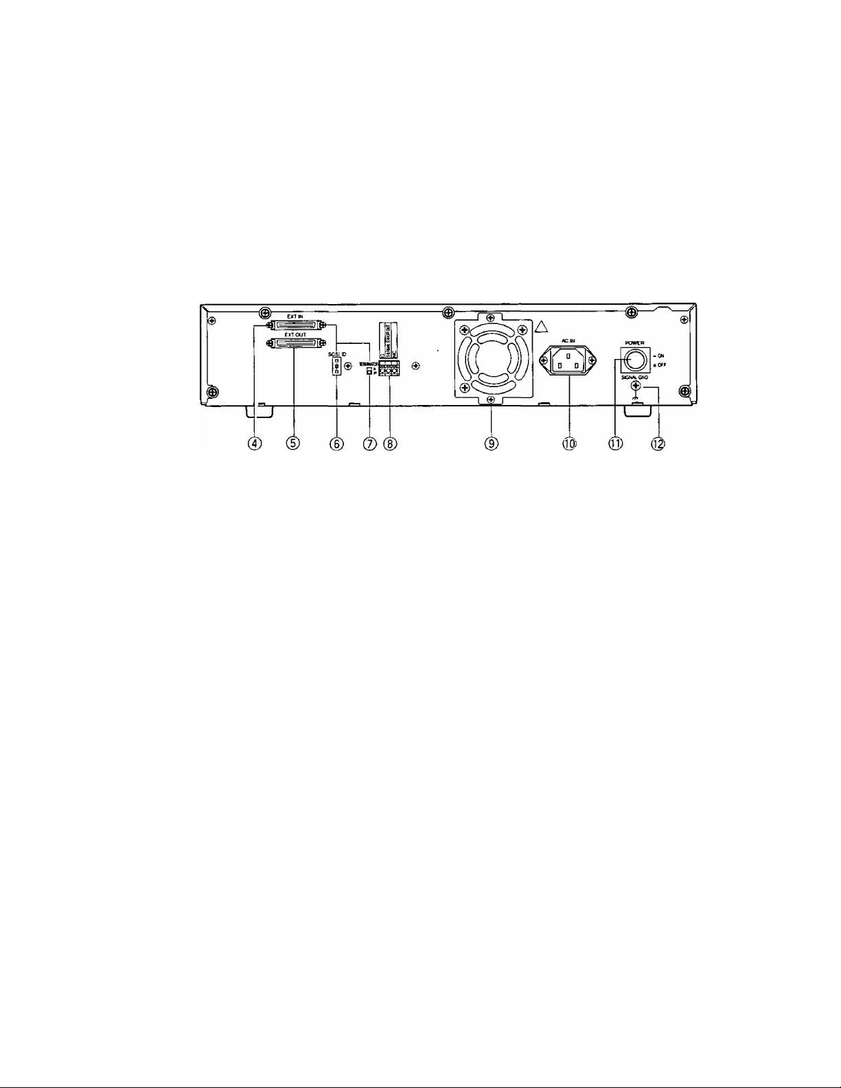
<REAR VIEW>
(4) SCSI In connector [EXT IN]
Connect the WJ-HD500 or other Extension Unit with
a SCSI cable.
(7) Termination Switch [TERMINATE ON/OFF]
Set this switch to ON when the extension unit is
located at the end of SCSI chain. Set this to OFF
unless the unit is located at the chain end.
® Terminal Board [THERMAL ERROR OUT] [G]
A thermal error signal is supplied and OPERATE
LED lights in orange when the inside temperature
exceeds or falls below the limit. Connect these ter
minals with the WJ-HD500,
[NC]: No connection
® Cooling Fan
@) AC Inlet [AC IN]
Connect the supplied power cord.
dj) Power Switch [POWER]
Turn on this switch (peripherals) first, then the power
of theWJ-HD500.
Confirm all HDD access lamps go out before turning
off this switch. Switch off the power of the WJ-
HD500 first, then turn off this switch (peripherals):
© SCSI Out connector [EXT OUT]
Connect another Extension Unit with a SCSI cable.
® SCSI ID Switch [SCSI ID -/+]
Press the upper or tower selector with a small head
ed screw driver to select the desired SCSI ID in the
chain.
© Signal GND Terminal [SIGNAL GND]
Connect this terminal with other equipment’s SIG
NAL GND to avoid possible grounding loop and
noise if required.
-3-
Page 4

Mounting HDDs
A maximum of 4 HDD units (locally procured) can be
mounted on one extension unit. This page describes
how to install #1 HDD. Repeat the same procedures as
#1 for #2 through #4 HDD.
The HDD units should be installed into the proper open
ings in order as shown. Never skip or reverse the posi
tion order of the HDD units.
1 Remove the front lid.
1-1 Loosen the front lid fixing screw,
1-2 Slide the lid to the right and remove it.
2 Remove the HDD bracket #1.
ХГГ
HDD Positions Inside The Lid
HDI^#4 HDD #3
1-1
HDD #2 HDD#1
2-1 Loosen 2 screws as shown.
2-2 Pull the bracket #1 out of the opening.
3 Disassemble the bracket #1.
Separate it into the fixing bracket and dummy bracket
by loosening 4 screws.
Keep the removed fixing bracket and 4 screws so that
they are to be used later.
4 Prepare an HDD unit.
5 Mount the HDD on the fixing bracket then fasten them
together with 4 screws.
Q»"
-4-
Page 5

6 Set the unit address with jumper connector on the
HDD as shown.
Note; For further details, refer to the instructions
included in the HDD unit.
HDD #2 & #4
(SLAVE)
o o
ooo
o o
o
Jumper Position
7 Place the HDD into the appropriate opening, then fix it
with 2 screws.
8 Plug the 2 connector harness to the installed HDD as
shown.
HDD #1 & #3
(MASTER)
o o O
o o o
Jumper Position
Jumper Connector
o
o
9 Repeat above steps for HDD #2 through #4.
10 Replace the front lid as before.
-5-
Page 6

■ Connection & Switch Setting
SCSI Connection
The Digital Disk Recorder WJ-HD500 controls
the extension units through the SCSI chain.
1 Connect between the EXT STORAGE port on
the WJ-HD500 and the EXT IN port on the 1st
extension unit with the supplied SCSI cable.
2 Connect between the EXT OUT port on the
1st extension unit and the EXT IN port on the
2nd extension unit with the supplied SCSI
cable.
Repeat connections in the same manner for
the following extension units.
3 The 3rd extension unit must be a WJ-
HDE505 if further extension unit is connect
ed, Use a WJ-HDE500 if the 3rd unit is locat
ed at the end of SCSI chain.
Extension is available up to 6 units.
Digital Disk Recorder
\
* Use a WJ-HDE505 for the 3rd unit position if further unit is extended.
Use a WJ-HDE500 if the 3rd position is the end of the SCSI chain.
Error Connection
Connect each error output with CONTROL port on the WJ-HDD500 rear panel as shown. The WJ-HD500 will display a warn
ing of the thermal error on the monitor.
WJ-HD500
CONTROL Port
13 1211109 B 7
o
nc
o
oc
o
o
LU
cc
UJ
Ü
HI
z
\
-
oo
Terminal board on
the Extension Unit
-6-
Page 7

r
Switch Settings
1 Set the MODE switch #2 on the rear of the WJ-HD500
to ON when connecting with the extension unit.
2 Set the SCSi iD for each unit by pressing the [-] and
[+] buttons on the rear of the extension unit.
0 to 5: Are applicable to the extension unit.
Note: SCSI ID 6 and 7 are reserved for WJ-HD500
Digital Disk Recorder.
3 Set the termination switch to ON or OFF.
ON: Is applied to the extension unit located at the
end of the SCSI chain.
OFF: Is used for other than the end unit.
1234
^ fatili
ON
MODE
SCSI ID
□
È
+
□
TERMINATION
ON
□
OFF
Rack Mounting
1 Remove the four rubber feet by removing four
screws from the bottom of the unit
2 Fix the Rack Mounting Brackets (supplied ) on both
sides the unit with 4 screws (M3X10 supplied).
3 .Install the unit in the rack securing it with four
screws (not supplied).
Cautions:
• Keep the temperature in the rack below 45'’C
(113‘>F).
• Do not block the ventilation opening or slots on the
cover to prevent the appliance from overheating.
M3X10 (Supplied)
-7-
Page 8

Troubleshooting
Phenomenon Cause What to do
No power is supplied.
Power cord connection is insufficient.
Securely plug the cord into AC outlet and AC
inlet..
HDD access lamps blink. The Inner connector is loosening. Securely plug the inner connector.
Thermal error, OPERATE indicator
lights in orange.
Ventilation openings or fan is blocked.
Cooling fan failed. Consult your dealer for the replacement.
Ambient temperature is too low. Use the unit within +5 *C to +45 “C,
SCSI ID setting
Remove obstacles.
Set ID number properly.
Termination Set termination properly.
Extension HDDs are not recog
nized.
SCSI cable Use the supplied cable & connect it securely.
Power-on sequence
Turn on peripherals first, then HD500!
HDD unit position Install HDD unit to the right position.
Specifications
Required Power:
Power Consumption:
Interface:
Operating Temperature:
Dimensions:
AC 120 V 60 Hz
55 W (inclusive of 4 HDD units if installed)
SCSI-2 (FAST SCSI) Half-pitch 50/pin D-Sub
+5 to +45 “C (41 ®Fto 113 T)
420 mm (W) x 88 mm (H) x 350 mm (D), rubber feet exclusive
16-9/16" X 3-7/16" X 13-13/16"
Weight:
WJ-HDE500: 7.3 kg (16 lbs)
WJ-HDE505: 8.0 kg (17.6 lbs)
Weight and dimensions indicated are approximate.
Specifications are subject to change without notice.
Accessory
Power Cord
SCSI Cable
Rack Mounting Bracket
Bracket Fixing Screw
......................
.......................
.....
........
,., 1 pc,
,,, 1 pc.
... 2 pcs,
,., 4 pcs.
Panasonic Security and Digital imaging Systems Company
A Division of Matsushita Electric Corporation of America
Executive Office: One Panasonic Way 3E-7, Secaucus, New Jersey 07094
Regionai Offices:
Northeast: One Panasonic Way, Secaucus, NJ 07094 (201) 348-7303
Southern: 1225 Northbrook Parkway, Suite 1-160, Suwanee, GA 30024 (770) 338-6838
Midwest: 1707 North Raidail Road, Eigin, IL 60123 (847)468-5211
Western: 6550 Katelia Ave., Cypress, CA 90630 (714) 373-7840
2000 © Matsushita Communication industrial Co,, Ltd. Aii rights reserved.
Panasonic Canada Inc.
5770 Ambier Drive, Mississauga,
Ontario, L4W 2T3 Canada (905)624-5010
Panasonic Sales Company
Division of Matsushita Electric of Puerto Rico Inc.
Ave, 65 de Infanteria, Km, 9,5
San Gabriei Industrial Park, Carolina,
Puerto Rico 00985 (809)750-4300
NM0900-1100
V8QA5621BN
(N)19
Printed in Japan
 Loading...