

Panasonic wj-hde400 Operation Manual
Extension unit
Installation Guide
Model No. WJ-HDE400
1
2
3
4
5
6
7
8
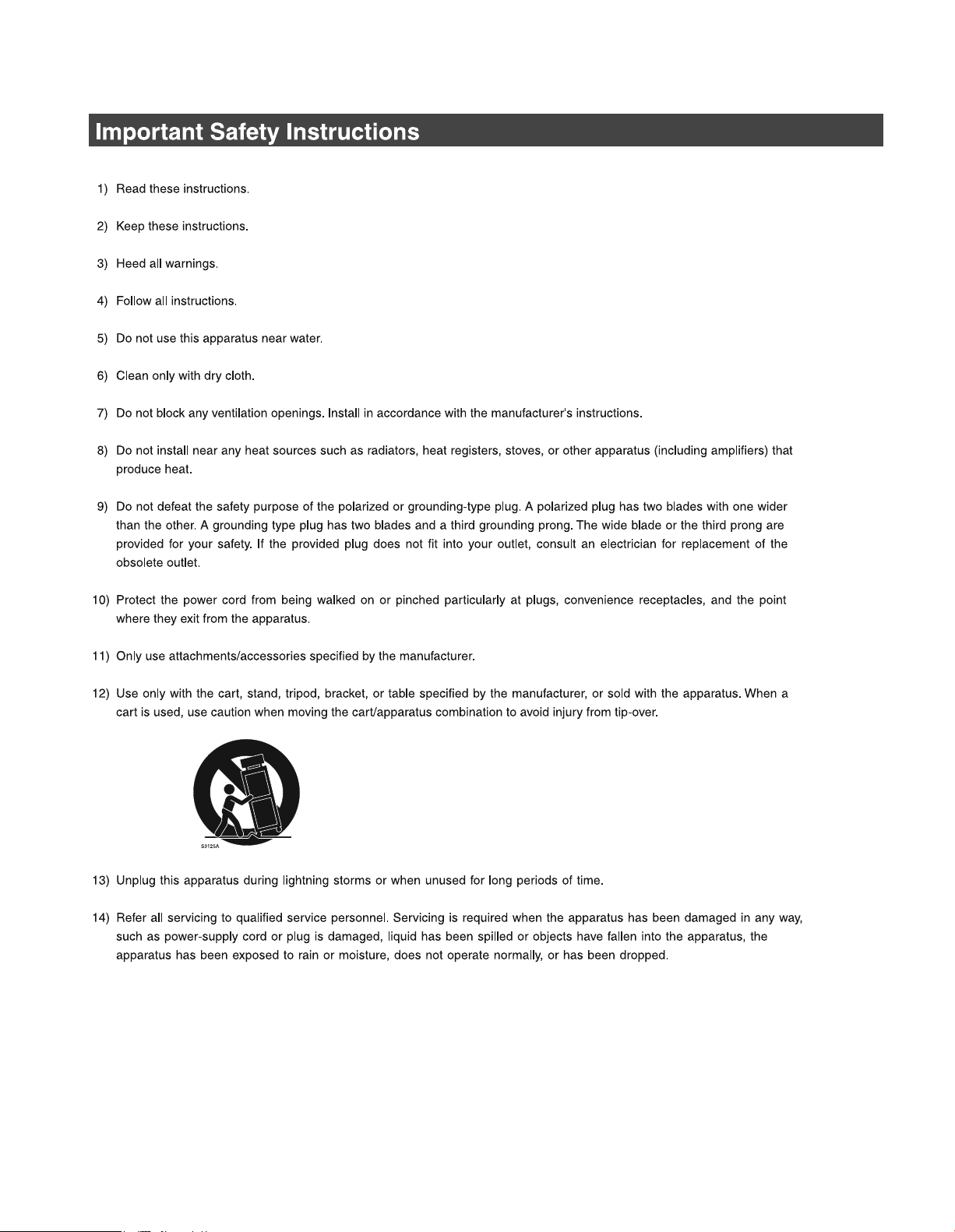
9
Before attempting to connect or operate this product,
please read these instructions carefully and save this manual for future use.
We declare under our sole responsibility that the product to which this
declaration relates is in conformity with the standards or other normative
documents following the provisions of Directives 2006/95/EC and
Preface
2004/108/EC.
Wir erklären in alleiniger Verantwortung, daß das Produkt, auf das sich
diese Erklärung bezieht, mit der folgenden Normen oder normativen
Dokumenten übereinstimmt. Gemäß den Bestimmungen der Richtlinie
2006/95/EC und 2004/108/EC.
WARNING:
• This apparatus must be earthed.
• Apparatus shall be connected to a main socket outlet with a protective earthing connection.
• The mains plug or an appliance coupler shall remain readily
operable.
• To prevent fire or electric shock hazard, do not expose this
apparatus to rain or moisture.
• The apparatus should not be exposed to dripping or splashing
and that no objects filled with liquids, such as vases, should be
placed on the apparatus.
• All work related to the installation of this product should be made
by qualified service personnel or system installers.
• The connections should comply with local electrical code.
CAUTION:
Before attempting to connect or operate this product, please
read the label on the bottom.
Nous déclarons sous note seule responsabilité que le produit auquel se
réfère la présente déclaration est conforme aux normes ou autres
documents normatifs conformément aux dispositions des directives
2006/95/CE et 2004/108/CE.
Nosotros declaramos bajo nuestra única responsabilidad que el
producto a que hace referencia esta declaración está conforme con las
normas u otros documentos normativos siguiendo las estipulaciones de
las directivas 2006/95/CE y 2004/108/CE.
Noi dichiariamo sotto nostra esclusiva responsabilità che il prodotto a
cui si riferisce la presente dichiarazione risulta conforme ai seguenti
standard o altri documenti normativi conformi alle disposizioni delle
direttive 2006/95/CE e 2004/108/CE.
Wij verklaren als enige aansprakelijke, dat het product waarop deze
verklaring betrekking heeft, voldoet aan de volgende normen of andere
normatieve documenten, overeenkomstig de bepalingen van Richtlijnen
2006/95/EC en 2004/108/EC.
Vi erklærer os eneansvarlige for, at dette produkt, som denne
deklaration omhandler, er i overensstemmelse med standarder eller
andre normative dokumenter i følge bestemmelserne i direktivene
2006/95/EC og 2004/108/EC.
Vi deklarerar härmed värt fulla ansvar för att den produkt till vilken
denna deklaration hänvisar är i överensstämmelse med
standarddokument, eller andra normativa dokument som framställs i
direktiv nr. 2006/95/EC och 2004/108/EC.
Ilmoitamme yksinomaisella vastuullamme, että tuote, jota tämä ilmoitus
koskee, noudattaa seuraavia standardeja tai muita ohjeellisia asiakirjoja,
jotka noudattavat direktiivien 2006/95/EC ja 2004/108/EC säädöksiä.
Vi erklærer oss alene ansvarlige for at produktet som denne erklæringen
gjelder for, er i overensstemmelse med følgende normer eller andre
normgivende dokumenter som følger bestemmelsene i direktivene
2006/95/EC og 2004/108/EC.
CAUTION:
An ALL-POLE MAINS SWITCH with a contact separation of at
least 3 mm in each pole shall be incorporated in the electrical
installation of the building.
CAUTION
The lightning flash with arrowhead symbol,
within an equilateral triangle, is intended to
alert the user to the presence of uninsulated
"dangerous voltage" within the product's
enclosure that may be of sufficient magnitude to constitute a risk of electric shock to
persons.
The exclamation point within an equilateral
triangle is intended to alert the user to the
presence of important operating and maintenance (servicing) instructions in the literature accompanying the appliance.
Power disconnection. Unit with or without ON-OFF switches
have power supplied to the unit whenever the power cord is
inserted into the power source; however, the unit is operational
only when the ON-OFF switch is in the ON position. Unplug the
power cord to disconnect the main power for all units.
For U.K.
FOR YOUR SAFETY PLEASE READ THE FOLLOWING TEXT CAREFULLY.
This appliance is supplied with a moulded three pin mains plug for your
safety and convenience.
A 5 amp fuse is fitted in this plug.
Should the fuse need to be replaced please ensure that the replace-
ment fuse has a rating of 5 amp and that it is approved by ASTA or BSI
to BS1362.
Check for the ASTA mark
fuse.
If the plug contains a removable fuse cover you must ensure that it is
refitted when the fuse is replaced.
If you lose the fuse cover the plug must not be used until a replacement
cover is obtained.
A replacement fuse cover can be purchased from your local Panasonic
Dealer.
IF THE FITTED MOULDED PLUG IS UNSUITABLE FOR THE SOCKET OUTLET IN YOUR HOME THEN THE FUSE SHOULD BE
REMOVED AND THE PLUG CUT OFF AND DISPOSED OF SAFELY.
THERE IS A DANGER OF SEVERE ELECTRICAL SHOCK IF THE
CUT OFF PLUG IS INSERTED INTO ANY 13 AMP SOCKET.
If a new plug is to be fitted please observe the wiring code as shown
below.
If in any doubt please consult a qualified electrician.
WARNING: This apparatus must be earthed.
The wires in this mains lead are coloured in accordance with the following code.
As the colours of the wire in the mains lead of this appliance may
not correspond with the coloured markings identifying the terminals in
your plug, proceed as follows.
The wire which is coloured green-and-yellow must be connected to
the terminal in the plug which is marked with the letter E or by the earth
symbol
The wire which is coloured blue must be connected to the terminal
in the plug which is marked with the letter N or coloured black.
The wire which is coloured brown must be connected to the terminal in the plug which is marked with the letter L or coloured red.
How to replace the fuse
Open the fuse compartment with
a screwdriver and replace the fuse
and fuse cover.
Green-and-yellow: Earth
Blue: Neutral
Brown:
or coloured green or green-and-yellow.
or the BSI mark on the body of the
IMPORTANT
Live
FUSE
2
For U.S.A.
The model number and serial number of this product may be
found in the unit. You should note the model number and
serial number of this unit in the space provided and retain this
book as a permanent record of your purchase to aid identification in the event of theft.
Model No.
Serial No.
For Canada
This Class A digital apparatus complies with Canadian ICES-
003.
For U.S.A.
NOTE: This equipment has been tested and found to comply
with the limits for a Class A digital device, pursuant to Part 15
of the FCC Rules. These limits are designed to provide
reasonable protection against harmful interference when the
equipment is operated in a commercial environment.
This equipment generates, uses, and can radiate radio
frequency energy and, if not installed and used in accordance
with the instruction manual, may cause harmful interference
to radio communications.
Operation of this equipment in a residential area is likely to
cause harmful interference in which case the user will be
required to correct the interference at his own expense.
FCC Caution: To assure continued compliance
use only shielded interface cables when connecting to
computer or peripheral devices). Any changes or modifica-
tions not expressly approved by the party responsible for
compliance could void the user's authority to operate this
equipment.
, (example -
3
4

Contents
Preface
Preface.............................................................................................................................................................. 6
HDD Fault Tolerance System...................................................................................................................... 6
Changing HDDs is Easy .................... .... ... ... ................................................................................................ 6
About these Operating Instructions................................................................................................................... 6
Precautions....................................................................................................................................................... 7
Major Operating Controls and Their Functions...................................................................9
Front View......................................................................................................................................................... 9
Inside the Front Cover .................................................................................................................................... 11
Rear View ....................................................................................................................................................... 12
Using the Brace ........................ ... .......................................... .................................................................... 12
Using the cable clamp ............................................................................................................................... 13
Installation and Setup
Getting Started......................................................................................................................14
Setup Procedure............................................................................................................................................. 14
Setting up the Rack ..............................................................................................................15
Rack Mounting................................................................................................................................................ 15
Connections.................................................................................................................................................... 16
Rack mounting positions................................................................................................................................. 17
Power Supply........................................................................................................................18
Turning On the Power..................................................................................................................................... 18
Turning Off the Power..................................................................................................................................... 18
Using the Front Panel for Operations.................................................................................19
About the Operational Mode Display.............................................................................................................. 19
Display During Single Operation................................................................................................................ 19
Display During RAID5/RAID6 Operation... ................................................................................................. 19
Initializing Settings .......................................................................................................................................... 20
HDD Unit......................................................................................................................................................... 21
Handling the HDD........................................................................................................................................... 22
Installing HDDs.......................................................................................................................................... 23
Installing HDDs by unit........................... ... ... ................................................................................. ............. 24
Removing HDDs............................................................. .......................................... ................................. 25
Removing HDDs by unit............................................................................................................................. 27
Setting the HDD's Operation Mode............................................................................................................ 28
HDD Error Recovery (During RAID Operation)............................................................................................... 29
Replacing Faulty HDD during RAID Operation.......................................................................................... 30
Attachments
Troubleshooting....................................................................................................................31
Problems......................................................................................................................................................... 31
Specifications........................................................................................................................33
WJ-HDE400.................................................................................................................................................... 33
Accessories...........................................................................................................................34
Standard Accessories.......................................................... .......................................... ................................. 34
5

Preface
The WJ-HDE400 is an extension unit for the network disk recorder (WJ-ND400), which is sold separately.
Up to 5 extension units can be connected to one network disk recorder.
A maximum of 9 hard disks (hereafter HDD) can be installed in an extension unit and operated as a RAID (Redundant Array of Inexpensive
Disks) to increase fault tolerance of the system.
HDD Fault Tolerance System
HDD fault tolerance is high because it is possible to use the RAID function.
This product is equipped with the RAID6 mode that can recover image data when two HDDs fail, in addition to the RAID5 mode that can recover
image data (RAID6 has two sets of error correcting code data). This prevents loss of recorded image data on large volume HDDs.
• To use the RAID5 mode you need to connect 3 or more HDDs, the RAID6 mode requires 4 or more HDDs.
• Theoretical volume when RAID5 mode enabled
Theoretical volume = HDD with smallest capacity in the unit x (number of HDDs in the unit −1)
• Theoretical volume when RAID6 mode enabled
Theoretical volume = HDD with smallest capacity in the unit x (number of HDDs in the unit −2)
• The capacity of the HDDs that are installed may be a few percents smaller.
Changing HDDs is Easy
You can install and remove HDDs by opening the front panel of the extension unit.
If more than two HDDs are installed, replacement can be done without stopping recording. Instructions are shown on the LCD to reduce
misoperations, and make maintaining and replacing HDDs easy.
Use the special HDD canister provided to install the HDD.
The HDD unit is an HDD that is in the special canister. The HDD units can be easily installed or removed from the HDD bay slots inside the front
cover of the extension unit.
* Contact your dealer for information on purchasing and replacing HDDs.
About these Operating Instructions
This manual describes how to install and connect the extension unit. It also descri
on the front panel of the network disk recorder.
Refer to the manuals provided with the network disk recorder to use the extension unit in a system.
bes how to
install and remove HDDs by operating the buttons
6

Precautions
z Refer all work related to the installation of this product to
qualified service personnel or system installers.
z Do not operate the unit beyond their its specified
temperature, humidity, or power source ratings.
Use the unit at temperatures between +5 ºC - +45 ºC {41 ºF - 113
ºF} and where the humidity is between 5 % - 90 %.
The input power source for NTSC model is 120 V AC 60 Hz, for
PAL model is 220 V - 240 V AC 50 Hz.
Performance and lifetime of hard disk drives are easily affected
by heat (used at high temperature) characteristically. It is
recommended to use this unit at temperatures between +20 ºC +30 ºC {68 ºF - 86 ºF}.
z POWER switch
The [POWER] switch is located on the rear of the unit. Even
though the [POWER] switch is set to "OFF", the power supply will
not be cut. To cut the power supply, unplug the power plug of the
unit from the AC outlet. When using the power supply control
unit, turn off the power of the power supply control unit.
z Hard disk drives
Hard disk drives are vulnerable to vibration. Handle them with
care.
It is possible to damage them if they are moved while their
motors are still running. Do not move them just after turning their
power on or off (for around 30 seconds).
⋅ A lifetime of hard disk drives is limited
It is recommen
of operation to prevent data loss from disk failures.
Write error may occur frequently after around 20 000 hours of
operation and the head and motor deterioration may occur
and will reach their lifetime after 30 000 hours of operation
when they have been used at the recommended ambient
temperature (approx. +25 ºC {77 ºF}).
When hard disk drive trouble occurs, replace it immediately.
Consult your dealer for servicing.
⋅ Hard disk drives are precise devices. Do not leave them
where the temperature is high and humid.
⋅ Do not touch the connector of the removable hard disk by
hand directly to protect the hard disk drive from static
electricity.
⋅ Take notice of the following for the removed hard disks.
⋅ Do not leave them where the temperature is high and
humid. It may cause condensation.
⋅ Place them where the tempe rature is between 0 ºC {32 ºF}
and 30 ºC {86 ºF} and humidity is between 20 - 40 % when
they are not used for a long time (six months or more).
Consult your dealer for further information.
⋅ Operate them for around an hour at least once every six
months when they are not used for a long time.
⋅ When placing them stacked, do not stack more than four
disks.
ded to replace them after around 18 000 hours
by use.
Grounding
z
firm that the wire is connected from the SIGNALGND
Con
terminal to earth ground.
A grounding connection must be made before connecting the
power plug of the unit to the main power supply.
When disconnecting the grounding wire, make sure that the
power plug of the unit is disconnected from the main power
supply.
z Avoid placing the unit near noise sources
If the unit is placed near noise sources such as fluorescent
lamps, noises may be produced. In this case, rewire avoiding the
noise sources, or move the unit to the place far from them.
z Places to avoid
Do not place the unit in the following places:
⋅ Places exposed to direct sunlight
⋅ Places subject to having strong vibration or impact
⋅ Near magnetic field sources such as a television or speakers
⋅ Place where condensation forms easily, where temperature
changes greatly, humid places
⋅ Steamy and oily places such as kitchens
⋅ Places which are not level
z Cleaning
Turn the power off when cleaning the unit. Otherwise it may
cause injuries.
Do not use strong or abrasive detergents when cleaning the unit
body.
Use a dry cloth to clean the unit when it is dirty.
When the dirt is hard to remove, use a mild detergent and wipe
gently.
z Indication label
Refer to the indication label placed on the surface of the unit as to
the indications of eq
z Handle the unit with care.
Do not strike or shake, as this may damage the unit.
z Do not strike or give a strong shock to the unit.
It may cause damage or allow water to enter the unit.
z Place the unit horizontally on a level surface.
Do not place the unit in an upright position. When stacking
multiple units, clear a space of more than 5 cm {1.97 "} from both
sides, the top, the bottom and the rear of the units.
z Avoid placing receptacles that contain liquids such as water
near the unit.
If liquid spills onto the unit, it may cause fire or an electric shock.
uipment classification and power source,
etc.
z Heat dissipation
Refer to the following to prevent fire and malfunction of the unit.
⋅ Do not block the front and rear for smooth ventilation.
⋅ Keep the unit 5 cm {1.97 "} or more away from the both sides
and the upper side.
⋅ Keep clean the ventilation openings of the unit to prevent
overheating.
⋅ A lifetime of the cooling fan is limited by use.
7

z Prevent condensation from forming on the surface of the
hard disk.
If this happens, do not turn on the power of the unit and leave the
unit for around 2 hours.
Wait until the dew evaporates in any of the following cases:
⋅ The unit is placed in an extremely humid place.
⋅ The unit is placed in a room where a heater has just been
turned on.
⋅ The unit is moved from an air-conditioned room to a humid
and high-temperature room.
⋅ When the unit has not been used for a certain period, turn on
the power of the unit (approximately once a week), and
perform recording/playback to prevent interferences with
functions.
⋅ We recommend that you make a note of your settings and
save them. This will help when you are required to change
the system configuration, or when unexpected trouble or
failure occurs.
⋅ Distributing, copying, disassembling, reverse compiling,
reverse engineering, and also exporting in violation of export
laws of the software provided with this product, is expressly
prohibited.
8
Major Operating Controls and Their Functions
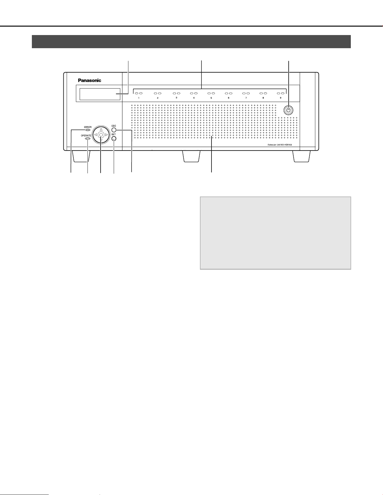
Front View
(1)
(4) (5) (6) (7) (8)
(1) LCD
Displays the extension unit's status (errors etc.) and
functions that are operated using the buttons on the front
panel.
(2) HDD indicators ("HDD1" to "HDD9")
HDD access indicator (right side)
Indicates the access status and problems of the HDD.
When errors occur on an HDD in RAID5/RAID6 mode, the
indicator lights or blinks red.
Blinks green : Accessing HDD
Off : Not accessing HDD
Lights red : Errors have occurred on HDD
(Data can be recovered by replacing
HDD)
• When in RAID5 mode, the first HDD
has errors
• When using RAID6, the first two
HDDs have errors
Blinks red : Errors have occurred on HDD
(Data cannot be recovered even if
HDD is replaced)
• When in RAID5 mode, the second
HDD has errors
• When in RAID6 mode, the third HDD
has errors
Lights orange and
red
(Alternately)
The indicators display the status of each of the drives from
HDD1 to HDD9, but if a system errors occur, each indicator
has the same display.
: Recovering data from drive in RAID5/
RAID6 mode.
(This indicator looks orange during
high-speed processing.)
(2)
(3)
(9)
Important:
• When the HDD indicators light red in RAID5/RAID6 mode,
quickly replace the HDD where the errors occurred. Contact
your dealer for information on replacing HDDs.
⋅ RAID5 mode:
Data cannot be recovered when two or more HDD
indicators are lighting or blinking red.
⋅ RAID6 mode:
Data cannot be recovered when three or more HDD
indicators are lighting or blinking red.
HDD status indicator (left side)
Shows the operating status of the HDDs.
Lights green : HDD power [On]
Blinks green : HDD for playback only
Blinks orange : Formatting HDD
Lights red : HDD format failed
Off : HDD power [Off]
(HDD formatted)
(only for playback, recording not possible)
HDD is not connected or not recognized.
(3) Key hole
Use to open and close the front cover.
Keep the key in a safe place.
Lock : Turn key to left.
Open : Turn key to right.
9

Major Operating Controls and Their Functions
(4) Error indicator [ERROR]
Blinks when errors or problems with the extension unit's
operation occur.
Blinks red : System errors
Blinks orange : Temperature is too high or too low.
Cooling fan stopped, etc
(5) Operate indicator [OPERATE]
Lights : Power [On]
Off : Power [Off]
(6) Arrow buttons (up, down, left, or right)
Use to move the cursor on the LCD and for direct input of
values.
(7) SET button [SET]
Use to set items on the LCD.
(8) Escape button [ESC]
Use to return to the previous screen when doing operations
on the LCD.
(9) Front cover
Open the front cover to add or replace HDD units.
Keep the front cover closed and locked during normal
operations.
10
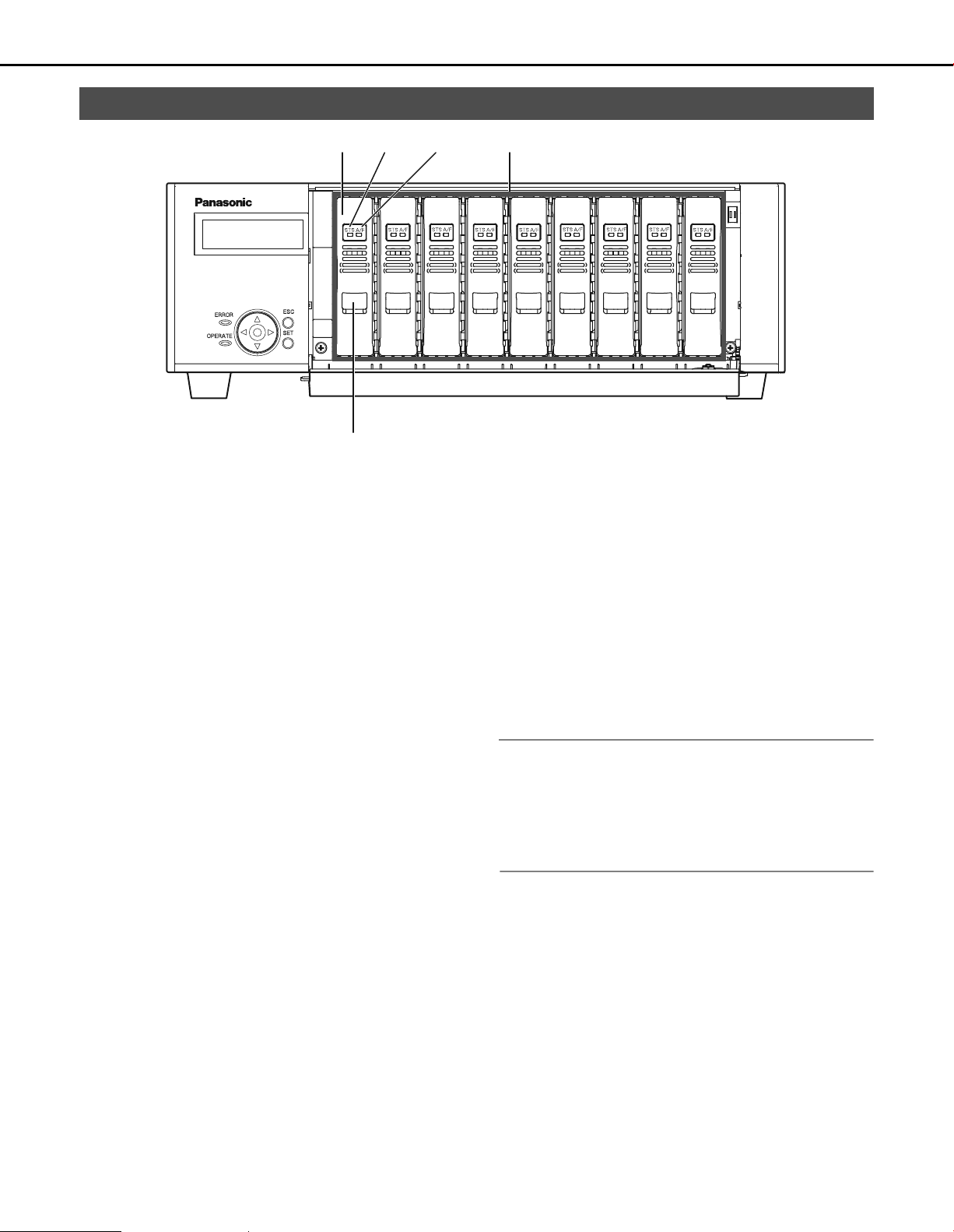
Inside the Front Cover
Major Operating Controls and Their Functions
(1)
(2) (3) (4)
(5)
(1) HDD unit
HDD in special canister
The HDDs can be added and replaced by using the front
panel of the network disk recorder. Refer to page 22 for
details. Contact your dealer for information on purchasing
and replacing HDDs.
(2) HDD status indicator [STS]
Shows the operating status of the HDDs.
Lights green : HDD power [On]
(Formatted)
Blinks green : HDD for playback only
(only for playback, recording not
possible)
Blinks orange : Formatting HDD
Lights red : HDD format failed
Off : HDD power [Off]
HDD is not connected or not
recognized.
(3) HDD access indicator [A/F]
Indicates the access status and problems with the HDD.
When errors occur on an HDD in RAID5/RAID6 mode, the
indicator lights or blinks red.
Blinks green : Accessing HDD
Off : Not accessing HDD
Lights red : Errors have occurred on HDD
(Data can be recovered by replacing
HDD)
• When in RAID5 mode, the first HDD
has errors
• When using RAID6, the first two
HDDs have errors
Blinks red : Errors have occurred on HDD
(Data cannot be recovered even if
HDD is replaced)
• When in RAID5 mode, the second
HDD has errors
• When in RAID6 mode, the third HDD
has errors
Lights orange and
red
(Alternately)
: Recovering data from drive in RAID5/
RAID6 mode.
(This indicator looks orange during
high-speed processing.)
(4) HDD bay slots
Up to 9 HDD units can be installed.
Note:
• Limiting factors for the RAID5/RAID6 mode
RAID5 mode : The RAID5 mode can be used when
more than three HDDs are installed.
RAID6 mode : The RAID6 mode can be used when
more than four HDDs are installed.
(5) Removal knob
Used when replacing the HDD units.
11
 Loading...