

Page 1
Extension Unit
Instructions
Model No. WJ-HDE300
Extension Unit
WJ-HDE
300
Before attempting to connect or operate this product,
please read these instructions carefully and save this manual for future use.
Page 2
WARNING:
• To prevent fire or electric shock hazard, do not expose this appliance to
rain or moisture. The apparatus shall not be exposed to dripping or
splashing and that no objects filled with liquids, such as vases, shall be
placed on the apparatus.
• All work related to the installation of this product should be made by
qualified service personnel or system installers.
CAUTION:
• Read the label on the rear of the unit for identification of this product,
and the power ratings.
CAUTION
RISK OF ELECTRIC SHOCK
DO NOT OPEN
For Canada
This Class A digital apparatus complies with canadian ICES-003.
Cet appareil numérique de la classe A est conforme à la norme
NMB-003 du Canada.
CAUTION: TO REDUCE THE RISK OF ELECTRIC SHOCK,
DO NOT REMOVE COVER (OR BACK).
NO USER-SERVICEABLE PARTS INSIDE.
REFER SERVICING TO QUALIFIED SERVICE PERSONNEL.
The lightning flash with arrowhead symbol, within an equilateral triangle, is
intended to alert the user to the presence of uninsulated "dangerous voltage"
within the product's enclosure that may
SA 1965
be of sufficient magnitude to constitute a
risk of electric shock to persons.
The exclamation point within an equilateral triangle is intended to alert the user
to the presence of important operating
and maintenance (servicing) instructions
in the literature accompanying the appliance.
SA 1966
Power disconnection. Unit with or without
ON-OFF switches have power supplied to
the unit whenever the power cord is inserted into the power source; however, the unit
is operational only when the ON-OFF
switch is in the ON position. The power
cord is the main power disconnect for all
units.
For U.S.A.
NOTE: This equipment has been tested and found to comply with the limits for a Class A digital device, pursuant to
Part 15 of the FCC Rules. These limits are designed to provide reasonable protection against harmful interference
when the equipment is operated in a commercial environment. This equipment generates, uses, and can radiate
radio frequency energy and, if not installed and used in
accordance with the instruction manual, may cause harmful
interference to radio communications.
Operation of this equipment in a residential area is likely to
cause harmful interference in which case the user will be
required to correct the interference at his own expense.
FCC Caution: To assure continued compliance, (example use only shielded interface cables when connecting to computer or peripheral devices). Any changes or modifications
not expressly approved by the party responsible for compliance could void the user’s authority to operate this equipment.
The serial number of this product may be found on the rear
of the unit.
You should note the serial number of this unit in the space
provided and retain this book as a permanent record of your
purchase to aid identification in the event of theft.
Model No. WJ-HDE300
Serial No.
2
Page 3

■ Important Safety Instructions
1) Read these instructions.
2) Keep these instructions.
3) Heed all warnings.
4) Follow all instructions.
5) Do not use this apparatus near water.
6) Clean only with dry cloth.
7) Do not block any ventilation openings. Install in accordance with the manufacturer's instructions.
8) Do not use near any heat sources such as radiators, heat registers, stoves, or other apparatus (including amplifiers) that
produce heat.
9) Do not defeat the safety purpose of the polarized or grounding-type plug. A polarized plug has two blades with one wider
than the other. A grounding-type plug has two blades and a third grounding prong. The wide blade or the third prong are
provided for your safety. If the provided plug does not fit into your outlet, consult an electrician for replacement of the
obsolete outlet.
10) Protect the power cord from being walked on or pinched particularly at plugs, convenience receptacles and the points
where they exit from the apparatus.
11) Only use attachments/accessories specified by the manufacturer.
12) Use only with the cart, stand, tripod, bracket, or table specified by the manufacturer, or sold with the apparatus. When a
cart is used, use caution when moving the cart/apparatus combination to avoid injury from tip-overs.
S3125A
13) Unplug this apparatus during lightning storms or when unused for long periods of time.
14) Refer all servicing to qualified service personnel. Servicing is required when the apparatus has been damaged in any way,
such as power-supply cord or plug is damaged, liquid has been spilled or objects fallen into the apparatus, the apparatus
has been exposed to rain or moisture, does not operate normally, or has been dropped.
3
Page 4

Contents
■ Important Safety Instructions . . . . . . . . . . . . . . . . . . . . . . . . . . . . . . . 3
■ General . . . . . . . . . . . . . . . . . . . . . . . . . . . . . . . . . . . . . . . . . . . . . . . 5
■ Precautions . . . . . . . . . . . . . . . . . . . . . . . . . . . . . . . . . . . . . . . . . . . . 5
■ Appearance . . . . . . . . . . . . . . . . . . . . . . . . . . . . . . . . . . . . . . . . . . . . 6
● Front View . . . . . . . . . . . . . . . . . . . . . . . . . . . . . . . . . . . . . . . . . . . 6
● Rear View . . . . . . . . . . . . . . . . . . . . . . . . . . . . . . . . . . . . . . . . . . . . 7
● Inside the Front Lid . . . . . . . . . . . . . . . . . . . . . . . . . . . . . . . . . . . . 8
■ Replacing/Mounting HDDs . . . . . . . . . . . . . . . . . . . . . . . . . . . . . . . . 9
● Procedures . . . . . . . . . . . . . . . . . . . . . . . . . . . . . . . . . . . . . . . . . . 9
■ Mounting in a Rack . . . . . . . . . . . . . . . . . . . . . . . . . . . . . . . . . . . . . . . 12
● Unit Layout . . . . . . . . . . . . . . . . . . . . . . . . . . . . . . . . . . . . . . . . . . . 12
● How to Mount . . . . . . . . . . . . . . . . . . . . . . . . . . . . . . . . . . . . . . . . . 13
■ Connections . . . . . . . . . . . . . . . . . . . . . . . . . . . . . . . . . . . . . . . . . . . . 14
● Procedures . . . . . . . . . . . . . . . . . . . . . . . . . . . . . . . . . . . . . . . . . . 14
■ Setup Procedures . . . . . . . . . . . . . . . . . . . . . . . . . . . . . . . . . . . . . . . 15
● Basic Setups . . . . . . . . . . . . . . . . . . . . . . . . . . . . . . . . . . . . . . . . . 15
● Changing Setups . . . . . . . . . . . . . . . . . . . . . . . . . . . . . . . . . . . . . 18
● Recovery of RAID5 Disk . . . . . . . . . . . . . . . . . . . . . . . . . . . . . . . . 21
● Unit Number Check . . . . . . . . . . . . . . . . . . . . . . . . . . . . . . . . . . . . 23
■ Troubleshooting . . . . . . . . . . . . . . . . . . . . . . . . . . . . . . . . . . . . . . . . . 26
■ Specifications . . . . . . . . . . . . . . . . . . . . . . . . . . . . . . . . . . . . . . . . . . . 27
■ Accessories . . . . . . . . . . . . . . . . . . . . . . . . . . . . . . . . . . . . . . . . . . . . 27
4
Page 5

■ General
The extension unit WJ-HDE300 can accommodate up to four hard disk drives per unit to add available disk space to the digital
disk recorder WJ-HD316A/WJ-HD309A series. Up to seven extension units can be connected to a digital disk recorder. The
units can be operated in RAID level 5* mode for high tolerance to disk error.
* RAID level 5 (Redundant Arrays for Independent Disks, independent data disks with distributed parity blocks)
RAID level 5 regards 3 or more drives as one drive, and it is possible to read data by automatically attaching error correction data even though one of the drives is broken. (It is impossible to read data if 2 or more drives are broken.)
RAID level 5 requires a minimum of 3 drives per unit.
When using the RAID function, the logical disk size of the extension unit will be as below.
Logical disk size = Smallest size of the disk among the disks in the extension unit x (Number of the disks in the extension
unit - 1) The actual space may be several percent lower than the logical space.
* Important
When set to RAID level 5, the digital disk recorder will not access the HDD preinstalled in it, but will access only the HDDs
in the extension unit.
■ Precautions
• Do not operate the appliance beyond its specified temperature, humidity or power source ratings.
Do not use the appliance in an extreme environment
where a high temperature or high humidity exists. Use
the appliance at temperatures within +5 °C to +45 °C
(41 °F to 113 °F) and humidity below 85 %.
The input power source for this appliance is 120 V AC
60 Hz.
• Avoid shock and vibration
Shock or vibration may damage the HDD.
The HDDs are fragile especially when the HDD motors
are revolving and the HDD POWER indicator lights. Be
sure to turn off either switch: the POWER switch on the
rear panel, or the HDD POWER switch inside the front
lid: before you mount the unit into a rack or dismount it.
Do not move the HDD for 30 seconds after turning off
the power.
• Pay attention to static electricity
Put your hand on a metallic surface to discharge static
electricity before installation.
Do not touch components mounted on the HDD directly
with your hand.
Hold only the two sides of the HDD when installing.
• Avoid condensation on the surface of the HDD.
If this happens, do not turn on the power of the appliance and leave the appliance for around 2 hours.
Wait until the dew evaporates in any of the following
cases.
• The appliance is moved to a place significantly different in temperature or humidity.
• The appliance is moved out from an air-conditioned
room.
• The appliance is placed in an extremely humid
place.
• The appliance is placed in a room where a heater
has just been turned on.
• Consumable parts
Contact your dealer about replacement when the time
comes.
A hard disk drive needs replacing after a certain length
(depends on the model) of operation.
Cooling fans also need replacing after around
20 000 - 30 000 hours of operation.
• Do not block the ventilation opening or slots on the
cover.
To prevent the appliance from overheating, place it at
least 5 cm (2 inches) away from the wall.
• Avoid placing the unit on an inclined surface.
Otherwise, malfunction or damage to the disk may
occur. Place the unit in a horizontal position.
5
Page 6
■ Appearance
ERROR
HDD 1 HDD 2 HDD 3 HDD 4
HDD
POWER
OPERATE
Extension Unit
WJ-HDE
qwe r t
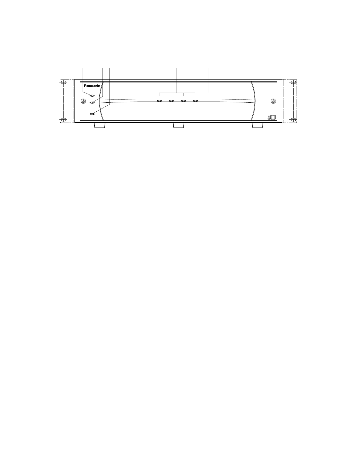
● Front View
q Error indicator [ERROR]
Lights when an error occurs. Refer to Troubleshooting
for details.
Red: System error
Orange: Thermal error or malfunction of the cooling fan.
w HDD power indicator [HDD POWER]
ON:
Indicates that the HDDs are powered.
OFF: Indicates that the HDDs are not powered.
Notes:
• Do not move or shock the unit while this indicator is
lit. Otherwise, the HDDs will be damaged.
• This indicator will light and go out by the setting of
the HDD POWER switch inside the front lid of the
unit, or by the operation on the HDD SAFETY MENU
of the digital disk recorder.
e Operate indicator [OPERATE]
Lights green when turning on the power switch on the
rear panel.
r HDD access indicators [HDD 1] [HDD 2] [HDD 3]
[HDD 4]
Each indicator lights to indicate the status of the
respective HDD.
Green: Indicates that the respective HDD is running
normally.
Red: Indicates that the respective HDD is the first faulty
drive among the HDDs in the unit.
Red blink: Indicates that the respective HDD is the
second or subsequent faulty drive among the HDDs
in the unit.
Orange-red alternate blink/Orange: Indicates that the
respective drive is currently being recovered in
RAID level 5 mode.
These indicators normally show the status of the
respective drive, but they work as a set when a system
error occurs. Refer to Troubleshooting for further information.
Important
When one of the indicators lights red, replace the
respective HDD immediately. If two or more indicators
light/blink red, it will be impossible to recover data.
There may be cases where it is eventually impossible to
recover data if two drives are coincidentally damaged
or the second drive fails during the data recovery
process.
6
t Front cover
Detach the front cover when it is necessary to install
HDDs or to operate the switches inside the unit.
Page 7
POWER
AC IN
SIGNAL GND
12
IN OUT
EXT
yu i i
o
!0
!1
!2
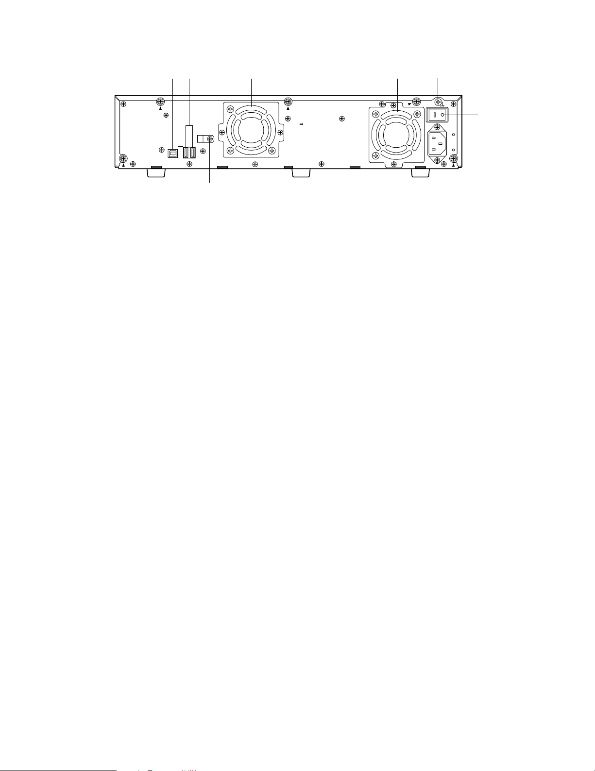
● Rear View
y Serial in connector [IN]
Connect the WJ-HD300 series digital disk recorder or
other extension unit with the supplied serial cable.
u Serial out connector [OUT1] [OUT2]
Connect another extension unit with the supplied serial
cable.
i Cooling fan
o Signal GND terminal [SIGNAL GND]
Connect this terminal if required, to the SIGNAL GND
terminal of other equipment to avoid a possible grounding loop and noise.
!0 Power switch [POWER]
Turn on the power of the unit with this switch before
turning on the power of the digital disk recorder, or turn
them on simultaneously. Otherwise, the HDDs will not
be mounted.
When turning off the power of the unit with this switch,
turn off the power of the digital disk recorder first, and
then turn off the power of this unit after confirming that
all HDD access indicators are not lit or blinking.
!1 AC inlet [AC IN]
Connect the supplied power cord.
!2 Cable clamp
7
Page 8

!3
!4
!5
!6
SINGLE RAID5
MODE
RESET
HDD POWER
RECOVER
OFF ON
w’
e’
q’
● Inside the Front Lid
q' Error indicators
Functions the same as on the front panel.
Red: System error
Orange: Thermal error or malfunction of the cooling fan.
w' HDD power indicator
Functions the same as on the front panel.
ON: Indicates that HDDs are powered.
OFF: Indicates that the HDDs are not powered.
e' Operate indicator
Functions the same as on the front panel.
Lights green when turning on the power switch on the
rear panel.
Important
• Changing the MODE switch will not be accepted when
the ERROR indicator lights red and/or when HDD 1-4
indicate a system error status by lighting red and
orange. When this happens, ask your dealer to solve
the error.
• When set to RAID5, the HDD preinstalled in the digital
disk recorder will not work. Instead, it is applied only to
the HDDs installed in the extension unit and the digital
disk recorder will perform storage and readout of the
image data by accessing the extension unit.
• The MODE switches of all extension units in a system
should be set to the same position, SINGLE or RAID5.
Otherwise, the system will malfunction.
• The available disk space of the unit can be logically
calculated as follows. The actual space may be several
percent lower than you calculated depending on the
HDD type used and their combination. The most efficient way is to use the same type drives.
When SINGLE is selected, it will be the sum of all
the HDD sizes.
When RAID 5 is selected, it will be as follows.
When 3 HDDs are in the unit: It will be double the
size of the smallest HDD size.
When 4 HDDs are in the unit: It will be triple the size
of the smallest HDD size.
For example, if 4 HDDs of 80 GB, 120 GB, and two
160 GB are mounted, the available disk space will
be 80 G x 3 = 240 GB.
!3 Reset button [RESET]
This button is located inside the unit. To access this
button, it is necessary to detach the front cover. Press
this button using a small screw driver (not supplied).
• When SINGLE is selected
After adding or replacing any of the HDDs, press this
button only. Refer to Setup Procedures for details.
• When RAID 5 is selected
This button is used in combination with the RECOVER
button and MODE switch after adding or replacing any
of the HDDs. Refer to Setup Procedures for details.
Important
Do not press the RESET button and the RECOVER
button simultaneously when SINGLE is selected.
Otherwise, the setting of the digital disk recorder
may be initialized and it may cause a malfunction.
!4 Mode switch [MODE]
RAID 5:
SINGLE: Applies SINGLE mode (no striping across dri-
Applies RAID level 5 mode (striping at the byte
level also stripe error correction information).
ves for data or error correction information).
position
8
Default
!5 HDD power switch [HDD POWER]
Use this switch in the ON position for normal operation.
ON: Supplies the power to the HDDs and the HDD
power indicators will light.
OFF:
Does not supply the power and the HDD power
indicators will go out.
!6 Recover button [RECOVER]
Use this button with the RESET button after replacing
the HDDs used in the RAID 5 mode to start data recovery.
Refer to page 12 for details.
Default position
Page 9
■ Replacing/Mounting HDDs
Up to four HDDs (locally procured) can be installed in an
extension unit.
HDD 2
HDD 1
Important
• Type of hard disk drive
Consult your dealer about hard disk drives. Use only
hard disk drives compatible with the extension unit. If
unauthorized hard disk drives are used, it may cause a
system error.
It is recommended that the same type drives having the
same capacity should be installed in the extension units
to maximize the usable capacity.
• The HDDs should be installed in the proper positions in
the order as shown above. Do not skip or reverse the
order of the HDD positions. Otherwise, the recorder will
not recognize the extension unit or wrongly mounted
drives.
HDD 4
HDD 3
• The replaced/added HDDs will be formatted.
SINGLE mode: Only the replaced/added HDD will be
formatted. For example, when the HDD
4 of the extension unit 2 is replaced,
only the HDD4 of the extension unit 2
will be formatted.
RAID 5 mode: All the HDDs of the extension units will
be formatted when a new HDD is
added or a preinstalled HDD is
removed. For example, when the HDD
4 of the extension unit 2 is added, all
the HDDs of the extension unit 2 will be
formatted.
● Procedures
1. HDD power-off procedures
Perform either of the following procedures depending
on the installation situations to stop the HDD motors.
Case 1: When the rear of the units is accessible, turn off
the power switches of the digital disk recorder
first, and turn off extension units.
• The MODE switches of all units in a system should be
set to the same position, SINGLE or RAID5. When
mixed, it will cause a system error. See Troubleshooting
for details.
• When applying the RAID5 mode, it requires a minimum
of 3 drives per unit. When only two drives are mounted
in position #1 and #2, the ERROR indicator will be lit
red, HDD3 indicator will be lit red, and HDD4 indicator
will blink red.
• When applying the RAID5 mode, the digital disk
recorder will not access the HDD preinstalled in it, but
will access only the HDDs in the extension unit.
• Do not change the installed positions after the system
has been operated. Otherwise, data readout will not be
performed
POWER
Case 2: When the rear of the units is inaccessible, for
example when mounted in a rack, open the
SETUP MENU of the digital disk recorder and set
the
HDD SAFETY MODE to ON. The extension
units will turn to the HDD power-off mode.
Refer to Setup Procedures of this manual and the
Operating Instructions included with the digital
disk recorder for details .
2. Detach the front cover and the front panel.
2 - 1
2-1 Remove the two screws.
9
Page 10

2-2 Slide the front cover to the left.
2-3 Pull the front cover toward you.
2 - 3
2 - 2
2 - 3
2-4 Disconnect the harness.
3. Remove two of the HDD mounting brackets.
• Remove the four screws and pull the brackets toward
you.
2 - 4
2-5 Remove the six screws (marked with ∆) and detach
the thin metal plate covering the front side.
2 -5
2-6 Disconnect the cables when adding or replacing
the HDD.
• When replacing an HDD, remove it from the bracket.
4. Prepare the HDDs to be fixed on the brackets.
• Release the static electricity from your body before
touching the HDDs.
• Put the conductive bag (in which the HDD was packed)
on a soft surface and place the HDD on it with the circuit board side down.
5. Fix the HDDs on the brackets.
5-1 Slide the HDD onto the bracket.
5-2 Tighten the four screws (supplied) to fix the HDD on
the bracket.
5-3 Repeat above steps to fix all the HDDs on the
bracket.
Do not use an electric screwdriver to fix them.
Recommended tightening torque = 0.49 N · m
{5 k
gf·cm}
10
2 - 6
6. Set all the HDDs as master using the jumper connector.
Note: This setting is subject to change without notice.
Refer to the diagram attached on the HDD or the
operating instructions of the HDD for the jumper
connector assignment.
Page 11

7. Place the brackets with the fixed HDDs into the unit and
fix them using the four screws removed in step 3.
• Do not use an electric screwdriver to fix them.
Recommended tightening torque = 0.784 N · m
{8 k
gf·cm}
8. Connect the cables.
11
. Attach the front cover as it was.
11-1 Align the left edges of both the front cover and the
unit, and then push the front cover onto the unit.
11-2 Slide the front cover to the right.
Note: The front cover may be attached and detached
as necessary in the next step of Setup Procedures.
Be careful not to damage the harness.
12
. Mount the unit referring to Mounting in a Rack.
13
. Connect the unit referring to Connections.
9. Attach the metal plate removed in step 2 with the six
screws (marked with ∆) previously removed.
10
. Connect the detached harness as it was.
14
. Set up the unit referring to Setup Procedures.
15
. Attach the front cover as it was.
15-1 Align the left edges of both the front cover and the
unit, and then push the front cover onto the unit.
15-2 Slide the front cover to the right.
15-3 Tighten the two screws.
11
Page 12

■ Mounting in a Rack
12
12
12
12
12
12
12
IN OUT
IN OUT
IN OUT
IN OUT
IN OUT
IN OUT
IN OUT
WJ-HDE300
Unit #1
WJ-HDE300
Unit #2
WJ-HDE300
Unit #3
WJ-HDE300
Unit #4
WJ-HDE300
Unit #5
WJ-HDE300
Unit #6
WJ-HDE300
Unit #7
Digital Disk
Recorder
2U
1U Space
2U
1U Space
2U
1U Space
2U
1U Space
2U
1U Space
2U
1U Space
2U
1U Space
2U
Serial cable (1 m, supplied)
COPY1
EXTSTORAGE
● Unit Layout
Unit Layout & Wiring
Note: Be sure to make a space of 1 U (44 mm) between the
units for ventilation in a rack.
Connection Diagram
Layer1
Layer2
Layer3
Layer4
Digital Disk Recorder
EXT STORAGE
IN
WJ-HDE300 #1
OUT2
IN
WJ-HDE300 #2
OUT2
IN
WJ-HDE300 #4
OUT1
WJ-HDE300 #3
OUT1
IN
WJ-HDE300 #5
WJ-HDE300 #6
IN
OUT2
IN
OUT1
IN
WJ-HDE300 #7
12
Page 13

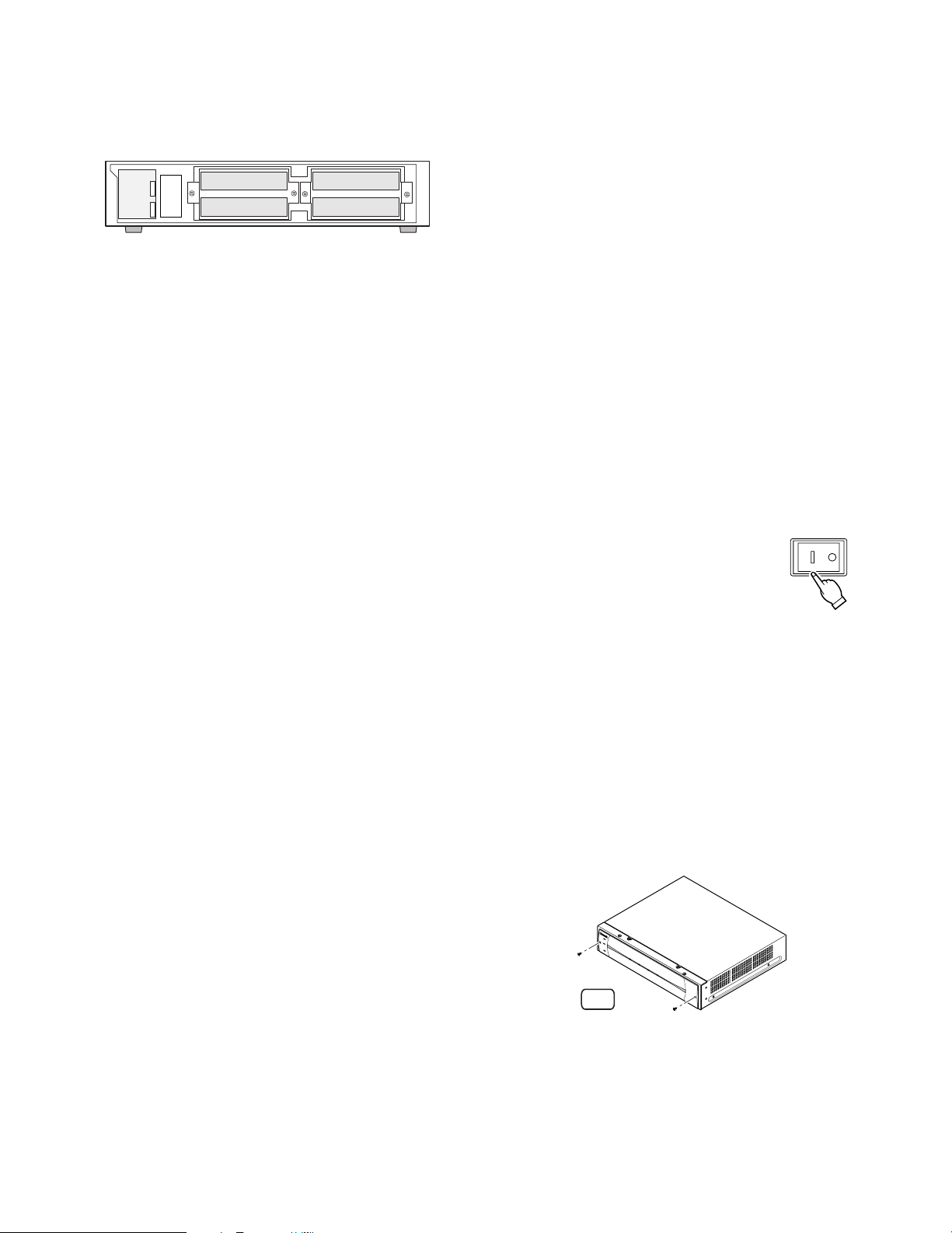
● How to Mount
Remove 6 screws
M4X10 (Supplied)
Rack Mounting Bracket (Supplied)
M5X12 (Not supplied)
1. Turn off the power of the unit and detach the plug from
the outlet.
When not turning off the power, open the front cover
and turn off the HDD POWER switch.
2. Remove the six rubber feet by removing the six screws
from the bottom of the unit
3. Fix the Rack Mounting Brackets (supplied) on both
sides of the unit with the four screws (M4X10, supplied).
4. Install the unit in the rack securing it with four screws
(M5x12, not supplied).
5. Turn on the power of the unit.
When the HDD POWER switch is turned off, turn it on
and attach the front cover as it was.
Cautions:
• Make a space of 1U (44 mm) between the units for ventilation, and install them in the rack as low as possible.
• Keep the temperature in a rack below 45 °C (113 °F).
• Install a fan in the rack when the ambient temperature is
above 30 °C (86 °F).
• Do not block the ventilation openings or slots on the
cover to prevent the unit from overheating.
13
Page 14

IN
OUT
CASCAKE
OUT
16
16
4
1515141413
2
1
13
12121111101099887766554433221
1
CAMERA
AUDIO IN AUDIO OUT
MONITOR OUT CASCADE IN
MONITOR (VGA) ALARM/CONTOROL
SERIAL ALARM
POWER
COPY
MODE
EXIT STORAGE10/100BASE-TRS-485(CAMERA)
PSÆDATA
AC IN
SIGNAL GND
1
3 2
POWER
AC IN
SIGNAL GND
12
IN OUT
EXT
POWER
AC IN
SIGNAL GND
12
IN OUT
EXT
POWER
AC IN
SIGNAL GND
12
IN OUT
EXT
POWER
AC IN
SIGNAL GND
12
IN OUT
EXT
IN
POWER
AC IN
SIGNAL GND
12
OUT
EXT
Digital Disk Recorder
WJ-HDE300 #1
WJ-HDE300 #2
WJ-HDE300 #5
WJ-HDE300 #4
WJ-HDE300 #3
WJ-HDE300 #6
WJ-HDE300 #7
EXT STORAGE
IN
IN IN
IN
IN
IN
IN
OUT1
OUT2
POWER
AC IN
SIGNAL GND
12
IN OUT
EXT
POWER
AC IN
SIGNAL GND
12
IN OUT
EXT
OUT1
OUT2
OUT1
OUT2
Cable clamp
Screw for the
cable clamp
12
IN OUT
EXT
Cable Clamp
Fixing screw
2
2
1
1
COPY
E
X
IT S
T
O
R
A
G
E
1
0/1
00B
A
S
E
-T
Remove this screw from
the unit and fix the cables
with the cable clamp
How to fix the cable clamp
How to fix the cables
■ Connections
You can connect up to seven extension units with the digital
disk recorder (the WJ-HD316A/WJ-HD309A series) as
shown below using the supplied serial cables.
● Procedures
1. Connect the EXT STORAGE port of the recorder and
the IN port of extension unit #1 using the supplied serial
cable.
2. Connect the OUT port of unit #1 and the IN port of unit
#2 using the supplied serial cable.
3. Repeat connections in the same way for the remaining
units.
4. Confirm the cable layout after connections.
5. Secure the cables using the clamp (supplied) and fix it
to the rear of the units.
Important
• Never use extension cables (locally procured). Be sure
to use the supplied serial cables for connection.
• Physical connections determine the unit number in a
system for each unit. Connect units with the recorder in
numeric order as shown in the figure. For example, connect the sixth and seventh units to the third unit when
five units have been already installed.
• Do not change connections after the system has run.
Otherwise, the recorder will no longer recognize the
extension units as before. You can change connections
only when you can discard all existing data stored in
the units.
• If turning off the power of a unit, none of the connected
following units will work because of interrupted data
transmission.
Note: When the system is connected in a different way from
the figure, a unit number check can be performed on
the HDD SAFETY MODE of the digital disk recorder.
Refer to Setup Procedures.
14
Page 15

■ Setup Procedures
The following pages describe procedures on how to set up or change the disk mode, how to recover data in RAID5, or
how to check the unit number using the HDD SAFETY MODE.
Notes:
• Refer to the operating instructions of the digital disk recorder WJ-HD316A/WJ-HD309A series for setup menu operations.
• The MODE switches of all units in a system should be set
to the same position, SINGLE or RAID5.
• The HDDs should be installed in the proper positions in the
order as shown in the figure. Do not skip or reverse the
order of the HDD positions. Otherwise, the recorder will not
recognize the extension unit.
• Do not change HDD positions of the extension unit after once the system has been operated. Otherwise, it will be
impossible to read the recorded data.
• The power-on order should be the extension units first and then the recorder. The power-off order should be the
recorder first and then the units.
• At least, three hard disk drives per extension unit are needed to run it in the RAID5 mode.
● Basic Setup
Setup to the SINGLE mode
Perform the following to set up the unit to the SINGLE mode
for the first time.
HDD 2
HDD 1
HDD 4
HDD 3
1 Power OFF
Confirm that the power of the recorder and the extension units are turned off.
2SINGLE
Set the MODE switch inside the front lid of the extension
unit to SINGLE.
MODE
SINGLE RAID5
3 Turn on the power switch of the extension units.
4 Turn on the power switch of the recorder.
→ The recorder will start.
5 HDD SAFETY MODE OFF
"HDD SAFETY MODE" menu will open after completing
the system check. Select OFF on the menu and press
the SET button on the recorder’s front panel.
→ The recorder will restart.
Notes:
• It will take about 3 or 5 minutes to complete the system check.
• When the system has been already run, "HDD
SAFETY MODE" menu will not appear. Skip to step
6.
POWER
SET
6 HDD DISK MENU will appear when the system check is
completed.
Perform formatting on the menu.
Refer to "
■
Formatting the Hard Disk" of the operating
instructions of the recorder.
Digital Disk Recorder
WJ-HD300A
FORMAT
HDD DISK MENU
TOP MENU
MIRROR ON REMOVE LINK
MAIN
EXT1
EXT2
EXT3
EXT4
EXT5
EXT6
EXT7
Information of recording areas : [SETUP/ESC] OK : [SET
MIRROR OFF
1234
160GB
160GB
160GB
160GB
*(160GB)
ADD (160GB)
160GB
LOST
160GB
160GB
160GB
160GB
*(ERROR)
ADD (ERROR)
160GB
-
RESTART EXIT
--
160GB
160GB
160GB
160GB
160GB
160GB
-
160GB
160GB
160GB
160GB
160GB
160GB
-
]
15
Page 16

Setup to the RAID5 mode
Perform the following to set up the unit to the RAID5 mode
for the first time.
1 Power OFF
Confirm that the power of the recorder and the extension units are turned off.
2 RAID5
Set the MODE switch inside the front lid of the extension
unit to RAID5.
Notes:
• It will take about 3 or 5 minutes to complete the system check.
• When the system has been already run, "HDD
SAFETY MODE" menu will not appear. Skip to step
6.
6 HDD DISK MENU will appear when the system check is
completed.
Perform formatting on the menu.
Refer to "
■
Formatting the Hard Disk" of the operating
instructions of the recorder.
MODE
SINGLE RAID5
3 Turn on the power switch of the extension units.
4 Turn on the power switch of the recorder.
→ The recorder will start.
5 HDD SAFETY MODE OFF
"HDD SAFETY MODE" menu will open after completing
the system check. Select OFF on the menu and press
the SET button on the recorder’s front panel.
→ The recorder will restart.
POWER
Digital Disk Recorder
WJ-HD300A
HDD DISK MENU
TOP MENU THE CANDIDATE FOR A FORMAT
ALL UNIT ONE UNIT
-
MAIN
480GB
EXT1
480GB
EXT2
480GB
EXT3
*(480GB)
EXT4
ADD (480GB)
EXT5
480GB
EXT6
LOST
EXT7
RETURN: [SETUP/ESC] OK : [SET
]
16
SET
Page 17

Formatting (Initialization) the hard disk
It is necessary to initialize the hard disk in the following
cases.
When replacing or adding the hard disk
When operating the unit for the first time
When having changed the hard disk mode between
SINGLE and RAID5
Note: It is unnecessary to initialize the hard disk when
recovery is to be executed in the RAID5 mode.
Important:
When the hard disk is formatted (initialized), all of the
recorded images will be deleted.
→ The password entry window will be displayed.
Digital Disk Recorder
WJ-HD300A
FORMAT
HDD DISK MENU
TOP MENU
MIRROR ON REMOVE LINK
MIRROR OFF
1234
160GB M
MAIN
160GB
EXT1
160GB
EXT2
160GB
EXT3
*(160GB)
EXT4
ADD (160GB)
EXT5
160GB
EXT6
LOST
EXT7
Information of recording areas : [SETUP/ESC] OK : [SET
160GB M
Enter the password.
160GB
160GB
160GB
*(ERROR)
EXECUTE
ADD (ERROR)
160GB
-
160GB
160GB
160GB
160GB
CANCEL
160GB
160GB
-
RESTART EXIT
160GB
160GB
160GB
160GB
160GB
160GB
-
]
1 Power up
• Turn on the power switches of the extension units
first. Then turn on the power switch of the digital
disk recorder.
Note: When the hard disk is replaced or removed,
the "TOP MENU" of the "HDD DISK MENU" will
be automatically displayed.
• Press the SET button on the front panel of the
recorder when a message " System check is completed" is displayed.
→ The "TOP MENU" of the "HDD DISK MENU" will
be displayed.
Digital Disk Recorder
WJ-HD300A
FORMAT
HDD DISK MENU
TOP MENU
MIRROR ON REMOVE LINK
MIRROR OFF
1234
160GB
MAIN
160GB
EXT1
160GB
EXT2
160GB
EXT3
*(160GB)
EXT4
ADD (160GB)
EXT5
160GB
EXT6
LOST
EXT7
Information of recording areas : [SETUP/ESC] OK : [SET
160GB
160GB
160GB
160GB
*(ERROR)
ADD (ERROR)
160GB
-
RESTART EXIT
--
160GB
160GB
160GB
160GB
160GB
160GB
-
160GB
160GB
160GB
160GB
160GB
160GB
-
]
SET
3 Password entry
• Enter the password for an administrator by rotating
the jog dial. Camera selection buttons are available
to enter numbers for password.
• Move the cursor to "EXECUTE" and press the SET
button.
4 Mode selection
● Initializing all hard disk (unit)
• Select "ALL FORMAT" for the SINGLE mode or "ALL
UNIT" for the RAID5 mode and press the SET button.
→ The "RECORDING AREA SETUP OF ALL DISKS"
will be displayed.
Digital Disk Recorder
WJ-HD300A
HDD DISK MENU
TOP MENU THE CANDIDATE FOR A FORMAT
MAIN
EXT1
EXT2
EXT3
EXT4
EXT5
EXT6
EXT7
ALL FORMAT
160GB
160GB
160GB
160GB
*(160GB)
ADD (160GB)
160GB
LOST
SELECTED DISC
1234
160GB
160GB
160GB
160GB
*(ERROR)
ADD (ERROR)
160GB
-
RETURN: [SETUP/ESC] OK : [SET
MIRROR FORMAT
160GB
160GB
160GB
160GB
160GB
160GB
-
160GB
160GB
160GB
160GB
160GB
160GB
-
]
SINGLE mode
2 Move the cursor to "FORMAT" and press the SET but-
ton.
SET
Digital Disk Recorder
WJ-HD300A
HDD DISK MENU
TOP MENU THE CANDIDATE FOR A FORMAT
ALL UNIT ONE UNIT
-
MAIN
480GB
EXT1
480GB
EXT2
480GB
EXT3
*(480GB)
EXT4
ADD (480GB)
EXT5
480GB
EXT6
LOST
EXT7
RETURN: [SETUP/ESC] OK : [SET
]
RAID5 mode
17
Page 18

● Initializing selected hard disk (the selected unit
when using the RAID5 mode)
• Select "SELECTED DISK" for the SINGLE mode or "ONE
UNIT" for the RAID5 mode and press the SET button.
→ The "DISK SELECT" menu for the SINGLE mode or
the "UNIT SELECTION" menu for the RAID5 mode
will be displayed.
Digital Disk Recorder
WJ-HD300A
HDD DISK MENU
THE CANDIDATE FOR A FORMAT DISK SELECT
Select HDD to be formatted,and press [SET]key.
1234
MAIN
EXT1
EXT2
EXT3
EXT4
EXT5
EXT6
EXT7
160GB
160GB
160GB
160GB
*(160GB)
ADD (160GB)
160GB
LOST
160GB
160GB
160GB
160GB
*(ERROR)
ADD (ERROR)
160GB
-
RETURN: [SETUP/ESC] OK : [SET
160GB
160GB
160GB
160GB
160GB
160GB
-
160GB
160GB
160GB
160GB
160GB
160GB
-
]
Digital Disk Recorder
WJ-HD300A
HDD DISK MENU
DISK SELECT THE SETTING METHOD
Auto Setup
All Copy Area
All Pre REC Area
MAIN
-
EXT1
480GB
480GB
EXT2
480GB
EXT3
*(480GB)
EXT4
ADD (480GB)
EXT5
480GB
EXT6
LOST
EXT7
RETURN: [SETUP/ESC] OK : [SET
Detailed Setup
]
RAID5 mode
• Select a setting method by moving the cursor and
press the SET button.
→ The confirmation menu of the recording area will be
displayed.
SINGLE mode
Digital Disk Recorder
WJ-HD300A
HDD DISK MENU
THE CANDIDATE FOR A FORMAT UNIT SELECTION
Select HDD to be formatted,and press [SET] key.
-
MAIN
EXT1
480GB
480GB
EXT2
480GB
EXT3
*(480GB)
EXT4
ADD (480GB)
EXT5
480GB
EXT6
LOST
EXT7
RETURN: [SETUP/ESC] OK : [SET
]
RAID5 mode
• Select the desired hard disk (or unit) and press the SET
button.
→ The "SETTING METHOD" menu will be displayed.
Digital Disk Recorder
WJ-HD300A
HDD DISK MENU
DISK SELECT THE SETTING METHOD
Auto Setup
MAIN
EXT1
EXT2
EXT3
EXT4
EXT5
EXT6
EXT7
All Copy Area
All Pre REC Area
1234
160GB
160GB
160GB
160GB
*(160GB)
ADD (160GB)
160GB
LOST
160GB
160GB
160GB
160GB
*(ERROR)
ADD (ERROR)
160GB
-
RETURN: [SETUP/ESC] OK : [SET
160GB
160GB
160GB
160GB
160GB
160GB
-
Detailed Setup
160GB
160GB
160GB
160GB
160GB
160GB
-
]
Digital Disk Recorder
WJ-HD300A
HDD DISK MENU
THE CANDIDATE FOR A FORMAT RECORDING AREA SETUP OF ALL DISK
Normal area Event area
90GB
1800GB
HDD Total capacity : 2790GB
RETURN: [SETUP/ESC] OK : [SET
Copy area
450GB
Free area
450GB
]
5 Area selection
• Select the desired recording area to be initialized
by moving the cursor and specify the capacity by
rotating the jog dial. Repeat this to assign two or
more areas.
• Confirm the capacities of the set recording areas
and press the SET button.
→ The confirmation dialog window will be dis-
played.
Digital Disk Recorder
WJ-HD300A
HDD DISK MENU
THE CANDIDATE FOR A FORMAT RECORDING AREA SETUP OF ALL DISK
Normal area Event area
90GB
Starting format of all HDDs,
1800GB
and all of data in HDDs
are going to be erased.
HDD Total capacity : 2790GB
Copy area
450GB
EXECUTE CANCEL
Free area
450GB
18
SINGLE mode
RETURN: [SETUP/ESC] OK : [SET
]
6 Execute
• Select "EXECUTE" and press the SET button.
→ The window will return to the TOP after complet-
ing the formatting.
Page 19

● Changing Setups
Changing the total number of HDD in
RAID5
Do the following when the total number of the hard
disks in the extension unit is increased (3 to 4) or
reduced (4 to 3) after the system has been operated.
Important:
• The MODE switches of all extension units in a system
should be set to the same position, SINGLE or RAID5.
Otherwise, the system will malfunction.
• At least three hard disk drives per extension unit are
needed to run it in the RAID5 mode.
• When the total number of the hard disks in an extension
unit is increased or reduced, all data previously stored
in the unit will be erased.
1 SAFETY MODE ON
Select ON for "HDD Safety Mode" and close the SETUP
MENU.
SETUP MENU
Advanced
REC Rate
Disk Info
Version Info
Disk End Mode
Disk Capacity
Date Delete
Event Log
Error Log
Access Log
Quick Menu
System
Recording
Switcher
MAIN
EXT1
EXT2
EXT3
EXT4
EXT5
EXT6
EXT7
■
■
Display
1234
160GB 160
15000h 15000h
160GB 160
15000h 15000h
160GB 160
15000h 15000h
160GB 160
15000h 15000h
160GB 160
15000h 15000h
160GB 160
15000h 15000h
160GB 160
15000h 15000h
160GB 160
15000h 15000h
Warning for Disk Life Time
HDD Safety Mode
GB
GB
160
15000h 15000h
GB
160
15000h 15000h
GB
160
15000h 15000h
160
GB
15000h 15000h
GB
160
15000h 15000h
GB
160
15000h 15000h
160
GB
15000h 15000h
Event Schedule
Comm
Maintenance
GB
160
GB
GB
160
GB
GB
160
GB
GB
160
GB
GB
160
GB
GB
160
GB
GB
160
GB
Remaining
Normal REC Area
Event REC Area
Copy Area
1 (Rear)
COPY
2 (Front)
COPY
3000h
OFF
LIVE
1800GB
1200GB
1000GB
1000GB
1000GB
3 Initializing the unit
1 Set the MODE switch to SINGLE.
SINGLE RAID5
2 While holding down the RECOVER but-
ton, press the RESET button.
3 While holding down the RECOVER button, release
the RESET button about 1 second later.
4 Release the RECOVER button after the HDD
POWER indicator turns on (5 seconds later).
5 Repeat the above steps when initializing two or
more units.
ERROR
HDD
POWER
OPERATE
RESET
MODE
SINGLE RAID5
HDD POWER
OFF ON
RECOVER
2
2
Press
Hold
HDD
POWER
HDD
POWER
SINGLE RAID5
4 Set the MODE switch back to RAID5.
5 SAFETY MODE OFF
• Select OFF on the HDD SAFETY MODE window and
press the SET button.
MODE
3
Release
4
Release
MODE
→ The recorder will restart and the HDD SAFETY MODE
window will be displayed.
2 Install/uninstall the hard disk
• Confirm that the HDD POWER indicator on the front
panel of the extension unit went out.
• Install or uninstall the hard disk referring to
Replacing/Mounting HDD.
• Go to the next step below after finishing the connection of the front cover harness with the unit while
the switches and buttons remain operable (step 11
of
■ Replacing/Mounting HDD).
→ The recorder will restart and the HDD
SET
DISK MENU will be displayed after the
system check is completed (3 - 5 minutes later).
Digital Disk Recorder
WJ-HD300A
■
HDD DISK MENU
TOP MENU THE CANDIDATE FOR A FORMAT
ALL UNIT ONE UNIT
-
MAIN
480GB
EXT1
480GB
EXT2
480GB
EXT3
*(480GB)
EXT4
ADD (480GB)
EXT5
480GB
EXT6
LOST
EXT7
RETURN: [SETUP/ESC] OK : [SET
]
• Perform the formatting of the changed extension unit.
19
Page 20

Changing hard disk mode
Do the following when the hard disk mode is changed
from SINGLE to RAID5 or vice versa after the system
has been operated.
Skip this section and perform settings in the same way
as "Setup to the SINGLE mode" or "Setup to the RAID5
mode" when the power switches of the recorder and
extension units are accessible.
2 Change the mode
• Confirm that the HDD POWER indicator on the front
panel of the extension unit went out.
• Change the MODE switch on the unit to SINGLE or
RAID5. The default position is SINGLE.
MODE
SINGLE RAID5
MODE
SINGLE RAID5
Important:
• The MODE switches of all extension units in a system
should be set to the same position, SINGLE or RAID5.
Otherwise, the system will malfunction.
• At least, three hard disk drives per extension unit are
needed to run it in the RAID5 mode.
• When the hard disk mode of the extension unit is
changed, all data previously stored in the unit will be
erased.
1 SAFETY MODE ON
Select ON for "HDD Safety Mode" and close the SETUP
MENU.
SETUP MENU
Advanced
REC Rate
Disk Info
Version Info
Disk End Mode
Disk Capacity
Date Delete
Event Log
Error Log
Access Log
Quick Menu
System
Recording
Switcher
MAIN
EXT1
EXT2
EXT3
EXT4
EXT5
EXT6
EXT7
■
■
Display
1234
160GB 160
15000h 15000h
160GB 160
15000h 15000h
160GB 160
15000h 15000h
160GB 160
15000h 15000h
160GB 160
15000h 15000h
160GB 160
15000h 15000h
160GB 160
15000h 15000h
160GB 160
15000h 15000h
Warning for Disk Life Time
HDD Safety Mode
GB
GB
160
15000h 15000h
GB
160
15000h 15000h
GB
160
15000h 15000h
160
GB
15000h 15000h
GB
160
15000h 15000h
GB
160
15000h 15000h
160
GB
15000h 15000h
Event Schedule
Comm
GB
160
GB
GB
160
GB
GB
160
GB
GB
160
GB
GB
160
GB
GB
160
GB
GB
160
GB
Maintenance
Remaining
Normal REC Area
Event REC Area
Copy Area
1(Rear)
Copy
2(Front)
Copy
30000h
ON
LIVE
1800GB
1200GB
1000GB
1000GB
1000GB
• Press the RESET button.
RESET
3 SAFETY MODE OFF
• Select OFF on the HDD SAFETY MODE menu and
press the SET button.
SET
20
→ The recorder will restart and the HDD SAFETY MODE
window will be displayed.
→ The recorder will restart and the HDD DISK
MENU will be displayed after the system check
is completed (3 - 5 minutes).
• Perform the formatting of the changed extension
unit.
Page 21

● Recovery of RAID5 Disk
Replacing and recovering RAID5 disk
When an HDD access indicator on the front panel of the
extension unit is lit red, it indicates that the hard disk drive
malfunctions.
Do the following to replace and recover the faulty hard disk.
Important:
• Immediately replace the hard disk when an HDD
access indicator is lit red. If one indicator is lit red and
the other blinks red, or the second hard disk fails during
the recovery process, it is impossible to recover the
data as a RAID5 system.
• When the ERROR indicator is lit red, it is a system error.
Consult your dealer. Refer to Troubleshooting.
• Refer to
types, mounting positions, and number of hard disk drives that should be installed in the unit.
1 SAFETY MODE ON
Select ON for "HDD Safety Mode" and close the SETUP
MENU.
■
Replacing/Mounting HDD for details on
2 Replacement
• Confirm that the HDD POWER indicator on the front
panel of the extension unit went out.
• Replace the faulty hard disk referring to
Replacing/Mounting HDD.
• Go to the next step below after finishing the connection of the front cover harness with the unit while
the switches and buttons remain operable (step 11
of
■ Replacing/Mounting HDD).
3 Data Recovery
1 Confirm that the MODE switch is set to RAID5.
MODE
SINGLE RAID5
2 While holding down the RECOVER button, press the
RESET button.
3 While holding down the RECOVER button, release
the RESET button about 1 second later.
4 Release the RECOVER button after the HDD
POWER indicator turns on (5 seconds later).
■
SETUP MENU
Advanced
REC Rate
Disk Info
Version Info
Disk End Mode
Disk Capacity
Date Delete
Event Log
Error Log
Access Log
Quick Menu
System
Recording
Switcher
MAIN
EXT1
EXT2
EXT3
EXT4
EXT5
EXT6
EXT7
■
■
Display
1234
160GB 160
15000h 15000h
160GB 160
15000h 15000h
160GB 160
15000h 15000h
160GB 160
15000h 15000h
160GB 160
15000h 15000h
160GB 160
15000h 15000h
160GB 160
15000h 15000h
160GB 160
15000h 15000h
Warning for Disk Life Time
HDD Safety Mode
GB
GB
160
15000h 15000h
GB
160
15000h 15000h
160
GB
15000h 15000h
160
GB
15000h 15000h
GB
160
15000h 15000h
GB
160
15000h 15000h
160
GB
15000h 15000h
Event Schedule
Comm
Maintenance
GB
160
GB
GB
160
GB
GB
160
GB
GB
160
GB
GB
160
GB
GB
160
GB
GB
160
GB
Remaining
Normal REC Area
Event REC Area
Copy Area
1 (Rear)
COPY
2 (Front)
COPY
3000h
OFF
LIVE
1800GB
1200GB
1000GB
1000GB
1000GB
→ The recorder will restart and the HDD SAFETY MODE
window will be displayed.
5 Repeat the above steps when initializing two or
HDD
POWER
HDD
POWER
ERROR
HDD
POWER
OPERATE
RESET
MODE
SINGLE RAID5
HDD POWER
OFF ON
RECOVER
2
2
Press
Hold
Release
4
Release
more units.
→ The HDD access indicator of the drive will blink red
and orange alternately during the recovery process
and will go out when the process is completed
Notes:
• For reference, it will take about 12 hours to complete
the recovery process for 160 GB data.
• Do not operate any switch or button of the extension
unit while the HDD indicator of the drive in the recovery
process blinks red and orange alternately. Otherwise,
the process will fail.
• The recorder can be operated during the data recovery
process, though the recovery time will be lengthened.
3
21
Page 22

4 HDD SAFETY MODE OFF
• Select OFF on the HDD SAFETY MODE window and
press the SET button.
→ The recorder will restart and enter the system
check mode. After 3 or 5 minutes, the system
check complete window will be displayed.
SET
• Select EXIT and press the SET button to close the
menu.
Digital Disk Recorder
WJ-HD300A
HDD DISK MENU
TOP MENU THE CANDIDATE FOR A FORMAT
ALL FORMAT
MAIN
EXT1
EXT2
EXT3
EXT4
EXT5
EXT6
EXT7
160GB
160GB
160GB
160GB
*(160GB)
ADD (160GB)
160GB
LOST
SELECTED DISC
1234
160GB
160GB
160GB
160GB
*(ERROR)
ADD (ERROR)
160GB
-
RETURN: [SETUP/ESC] OK : [SET
MIRROR FORMAT
160GB
160GB
160GB
160GB
160GB
160GB
-
160GB
160GB
160GB
160GB
160GB
160GB
-
]
22
SET
• Press the SET button to display the HDD DISK
MENU.
Page 23

Setting/Changing hard disk mode after
resetting error
It is impossible to change or set up the hard disk mode
when the ERROR indicator and one of HDD access
indicators is lit red or is blinking. To set or change the
mode, repair the system so the indicators go out.
Refer to Troubleshooting of this manual and the operating instructions of the digital disk recorder for details.
Important:
• When an HDD indicator is lit or blinking red, the
HDD is faulty and should be replaced performing
the following steps.
• When less than three hard disks are mounted or the
mounted positions are wrong in RAID5, the HDD
indicators will blink red and be lit red. Add hard
disk(s) or correct the positions and then set up the
extension unit again.
• When the ERROR indicator is lit red and all HDD
access indicators are lit red and orange, it is a system error. Consult your dealer.
1 SAFETY MODE ON
Select ON for HDD Safety Mode on the SETUP MENU
and press the SET button.
→ The recorder will restart and the HDD SAFETY
MODE window will be displayed.
2 Replacement of faulty HDD
• Confirm that the HDD POWER indicator on the front
panel of the extension unit has gone out.
• Replace the faulty hard disk referring to
■ Replacing/Mounting HDD.
• Go to the next step below after finishing the connection of the front cover harness with the unit while
the switches and buttons remain operable (step 11
of
■ Replacing/Mounting HDD).
SETUP MENU
Advanced
REC Rate
Disk Info
Version Info
Disk End Mode
Disk Capacity
Date Delete
Event Log
Error Log
Access Log
Quick Menu
System
Recording
Switcher
MAIN
EXT1
EXT2
EXT3
EXT4
EXT5
EXT6
EXT7
■
■
Display
1234
160GB 160
GB
15000h 15000h
160GB 160
GB
15000h 15000h
160GB 160
GB
15000h 15000h
160GB 160
GB
15000h 15000h
160GB 160
GB
15000h 15000h
160GB 160
GB
15000h 15000h
160GB 160
GB
15000h 15000h
160GB 160
GB
15000h 15000h
Warning for Disk Life Time
HDD Safety Mode
Event Schedule
Comm
GB
160
GB
160
15000h 15000h
GB
160
GB
160
15000h 15000h
160
GB
160
GB
15000h 15000h
160
GB
160
GB
15000h 15000h
GB
160
GB
160
15000h 15000h
GB
160
GB
160
15000h 15000h
160
GB
160
GB
15000h 15000h
Maintenance
Remaining
Normal REC Area
Event REC Area
Copy Area
1(Rear)
Copy
2(Front)
Copy
30000h
ON
LIVE
1800GB
1200GB
1000GB
1000GB
1000GB
SET
3 Initialization
1 Set the MODE switch to SINGLE.
MODE
SINGLE RAID5
2 While holding down the RECOVER button, press the
RESET button.
3 While holding down the RECOVER button, release
the RESET button about 1 second later.
4 Release the RECOVER button after the HDD
POWER indicator turns on.
ERROR
HDD
POWER
OPERATE
RESET
MODE
SINGLE RAID5
HDD POWER
OFF ON
RECOVER
2
2
Press
Hold
HDD
POWER
HDD
POWER
3
Release
4
Release
23
Page 24

4 MODE switch setting
Set the MODE switch to SINGLE or RAID5.
→ After that, the HDD DISK MENU respective to the
selected mode (SINGLE or RAID5) will be displayed automatically.
MODE
SINGLE RAID5
MODE
SINGLE RAID5
5 SAFETY MODE OFF
• Select OFF and press the SET button.
→ The recorder will restart. After 3 or 5 minutes,
the system check complete window will be displayed.
SET
Digital Disk Recorder
WJ-HD300A
• Perform formatting referring to
HDD DISK MENU
TOP MENU THE CANDIDATE FOR A FORMAT
ALL UNIT ONE UNIT
-
MAIN
480GB
EXT1
480GB
EXT2
480GB
EXT3
*(480GB)
EXT4
ADD (480GB)
EXT5
480GB
EXT6
LOST
EXT7
RETURN: [SETUP/ESC] OK : [SET
]
■ Formatting
(Initialization) the Hard Disk of the operating instructions of the recorder.
24
Page 25

● Unit Number Check
How to check the unit number
Each extension unit is given a unit number depending
on the connected position. Refer to
this manual for the recommended connection form and
the unit numbers given to the respective extension
units.
Do the following to check which unit numbers are given
to the extension units.
Important
• Do not change the connections of the extension
units after the system has been operated.
Otherwise, the recorder will fail to recognize the
extension units.
1 SAFETY MODE ON
Select ON for HD Safety Mode and press the SET button.
SETUP MENU
Advanced
REC Rate
Disk Info
Version Info
Disk End Mode
Disk Capacity
Date Delete
Event Log
Error Log
Access Log
Quick Menu
System
Recording
Switcher
MAIN
EXT1
EXT2
EXT3
EXT4
EXT5
EXT6
EXT7
■
■
Display
1234
160GB 160
15000h 15000h
160GB 160
15000h 15000h
160GB 160
15000h 15000h
160GB 160
15000h 15000h
160GB 160
15000h 15000h
160GB 160
15000h 15000h
160GB 160
15000h 15000h
160GB 160
15000h 15000h
Warning for Disk Life Time
HDD Safety Mode
GB
GB
160
15000h 15000h
GB
160
15000h 15000h
GB
160
15000h 15000h
160
GB
15000h 15000h
GB
160
15000h 15000h
GB
160
15000h 15000h
160
GB
15000h 15000h
Event Schedule
Comm
GB
160
GB
160
GB
160
GB
160
GB
160
GB
160
GB
160
Maintenance
Normal REC Area
GB
Event REC Area
Copy Area
GB
Copy
GB
Copy
GB
GB
GB
GB
ON
■
Connections of
LIVE
Remaining
1800GB
1200GB
1000GB
1(Rear)
1000GB
2(Front)
1000GB
30000h
2 Unit number check
• Confirm that the HDD POWER indicators on the
front panel of the extension units have gone out.
•On the front panel of the recorder, press the
Camera Selection buttons from [1] to [7] in order.
263
SEQ
5
41
7
→ All the HDD access indicators of the respective
unit will be lit red for 5 seconds. For example,
when the button [1] is pressed, the HDD access
indicators on the extension unit #1 will be lit.
HDD 1 HDD 2 HDD 3 HDD 4
3 SAFETY MODE OFF
Select OFF on the HDD SAFETY MODE window and
press the SET button.
SET
→ The recorder will restart and the HDD SAFETY
MODE window will be displayed.
SET
→ The recorder will restart. After 3 or 5 minutes of
system check, it will run in normal operation
mode.
Note: The HDD access indicator that is lit red or blink-
ing due to failure of the hard disk in RAID5 will keep
its state while the other indicators of the unit are lit
red to display the unit number.
25
Page 26

■ Troubleshooting
Symptom
No power is supplied. Insufficient power cord connection
POWER switch or HDD POWER switch is
turned off.
ERROR indicator lights orange.
Thermal error has stopped the
unit.
ERROR indicator lights red. System fault
Extension unit or added HDD is
not recognized.
Cooling fan(s) may be faulty.
Ambient temperature exceeds the operable
range.
Ventilation may be blocked.
Connection cables other than supplied may
have been used.
Insufficient connector junction
Powering up the recorder and units in opposite
order
The recorder and units are connected to different AC mains
HDD installation position is wrong.
MODE switch setting
Cause
What to do
Securely connect the power cord.
Turn on the POWER switch and HDD
POWER switch.
Repair cooling fan(s).
Arrange the ambient temperature so that
it lies within the acceptable range.
Remove obstacles blocking the openings or slots. See below for cleaning.
Repair is required.
Use the supplied cable.
Firmly join the cables and connectors.
The order should be "the extension units
first, then the recorder" or at the same
time.
Keep the above order for powering up,
or rearrange the AC mains connection to
the same source.
Install HDDs in order from the position
#1, #2, #3, and #4. Never skip or reverse
the order.
Set the MODE switch appropriately.
HDD access indicator alternately
blinks orange and red or blinks
green though no recording/playback.
Data recovery fails after replacing the HDDs in the RAID 5
mode.
HDD access indicator light blinks
red.
HDD access indicator lights red
and orange.
In recovery process of RAID5
Automatic periodic (every 5 seconds) data
check in RAID5
The HDD to be recovered may be faulty.
Size of the new HDD may be smaller than
before although nominally the same.
The HDDs have not been replaced correctly.
The cables are not connected correctly to the
HDDs.
Disk drive is faulty in RAID5 mode.
The steady light means it is the first faulty drive,
the blinking light means it is one of the later
ones.
System fault
Red and orange lighting of these four bits displays error status as shown below.
8
: Red
9888
8988
9988
8898
9898
8998
9998
8889
8989
9989
8899
8999
: Orange
9
: Hardware error
: Hardware error
: Hardware error
: Hardware error
: Hardware error
: Hardware error
: Hardware error
: Hardware error
: Hardware error
: Hardware error
: Hardware error
: Disk CRC error
Not a problem
Repair the faulty HDD.
Install an HDD larger than before or the
same size.
Never skip or reverse the position.
Check that the cables are connected to
the HDDs correctly and firmly.
Repair the faulty HDD and implement
the recovery process.
Repair is required.
26
Page 27

■ Specifications
Required power: 120 V AC 60 Hz
Power consumption: 85 W (including 4 HDDs when installed)
Interface: 2-wire serial, 480 Mbps logical speed
Operating temperature: +5 °C to +45 °C (41 °F to 113 °F)
Operating humidity: Less than 85 %
Dimensions: 420 mm (W) x 88 mm (H) x 350 mm (D), rubber feet exclusive
19-9/16" (W) x 3-7/16" (H) x 13-13/16" (D)
Weight: 7.2 k
Weight and dimensions indicated are approximate.
Specifications are subject to change without notice.
g (16 lbs) (not including hard disk drives)
■ Accessories
Operating instructions (this document)....................... 1 pc.
The following are for installation.
Power cord ................................................................. 1 pc.
Serial cable ................................................................. 1 pc.
Rack mounting bracket .............................................. 2 pcs.
Bracket fixing screw ................................................... 4 pcs.
HDD fixing screw ...................................................... 16 pcs.
27
Page 28

Panasonic Digital Communications & Security Company
Unit of Matsushita Electric Corporation of America
Security Systems Group
www.panasonic.com/cctv
Executive Office: One Panasonic Way 3E-7, Secaucus, New Jersey 07094
Zone Office
Eastern: One Panasonic Way, Secaucus, NJ 07094 (201) 348-7303
Central: 1707 N.Randal Road, Elgin, IL 60123 (847) 468-5205
Western: 6550 Katella Ave., Cypress, CA 90630 (714) 373-7840
PANASONIC CANADA INC.
5770 Ambler Drive, Mississauga,
Ontario, L4W 2T3 Canada (905)624-5010
PANASONIC SALES COMPANY
DIVISION OF MATSUSHITA ELECTRIC OF PUERTO RICO INC.
San Gabriel Industrial Park 65th Infantry Ave. KM. 9.5 Carolina,
P.R. 00985 (809)750-4300
2004 © Matsushita Electric Industrial Co., Ltd. All rights reserved. NM0104-2104 3TR001883CAA Printed in Japan
 Loading...