

Page 1
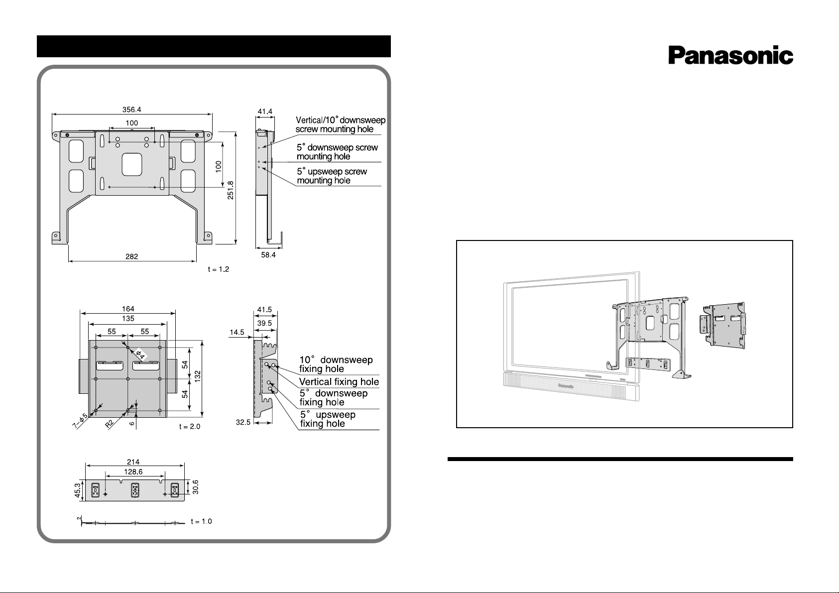
Wall mounting bracket dimensional drawings
Wall mounting bracket A (Main unit side)
Wall mounting bracket B (Wall side)
Wide-screen LCD Television (22LT SERIES)
Wall Mount Kit
Installation Manual
Model No. TY-WK22LT1U
Metal plate (main unit side)
© 2002 Matsushita Electric Industrial Co., Ltd. All rights reserved
Printed in Japan
[Unit: mm]
MBS0202-0(MS)
● Please read this instruction manual carefully for the correct usage. After reading,
retain it in a convenient location for future reference.
● To achieve the best possible performance and to maintain safety, always request a
certified professional for the installation of the wall mounting bracket.
● Retain all removed parts. They may become necessary when returning to the original
installation condition.
●
Caution: This bracket intended for use only with Panasonic LCD TV Model TC-22LT1/TX22LT2 series. Use with other apparatus may result in instability causing possible injury.
TQZH376
Page 2

Safety precautions
To prevent injury to the user and others and to prevent damage to property , items that must
be followed are explained as shown below.
■ The following displays categorize the degree of danger when mishandled.
WARNING
CAUTION
■ Items that must be followed are explained using the following symbols.
This symbol indicates that the item must be followed with caution.
This symbol indicates that the item is prohibited.
This symbol indicates that the item must always be followed.
Possibility of serious injury and even death when
mishandled.
Possibility of injury or damage to surrounding
property.
Be sure to follow
WARNING
Installation
■ Be aware of safety factors
concerning the mounting
strength
Insufficient strength may
cause the wide-screen
LCD television to fall, resulting in bodily injury.
CAUTION
■ Do not hang anything from the
wide-screen LCD television,
place a stepladder against it,
etc.
The wide-screen LCD television may become damaged or it may fall, causing
Prohibited
bodily injury.
WARNING
Installation
■ Installation to be performed by
certified personnel only.
Inadequate installation
may cause the wide-screen
Prohibited Prohibited
LCD television to fall, resulting in bodily injury.
■ Do not install where tolerance
is weak.
2
If the tolerance of the
mounting location is weak,
the wide-screen LCD television may fall resulting in
bodily injury.
Installation
■ Do not install in humid or
dusty areas, or where the
wide-screen LCD television
may be exposed to lampblack,
steam or heat.
Fire or electrical shock may
occur as a result.
Prohibited
■ Make sure there is sufficient
air circulation so that the ambient temperature does not
exceed 35°C.
Heat may build up within the
wide-screen LCD television, causing fire as a result.
3
Page 3
CAUTION
Cautions concerning installation work
Installation
■ Do not install with the wide-
screen LCD television facing
downward, on its side, or upside down.
Heat may build up within the
wide-screen LCD televi-
Prohibited
sion, causing fire as a result.
■ Maintain space of at least 5 cm
on top and to the sides of the
wide-screen LCD television
and at least 4 cm in the rear.
Vent holes are located on
the rear of the wide-screen
LCD television. Blocking
these holes may result in
fire.
■ Always remove the wall
mounting bracket when removing the wide-screen LCD
television.
Injury may result when accidentally hitting the projected parts.
Take caution when removing for repairs, etc.
■ The wide-screen LCD televi-
sion is heavy. Always work in
pairs.
The television may fall,
causing bodily injury.
To achieve the best possible performance and to maintain safety, always
request a certified professional for the installation of the wall mounting
bracket.
1
The stand of the wide-screen LCD television must be removed.
Before performing work, always turn off the power and disconnect the power
plug of the AC adapter from the wall outlet.
2
Allow sufficient strength for safety.
The weight of the wide-screen LCD television is approximately 9.5 kg.
When mounting on a wall, perform work so that it can withstand the weight of
the television and so that the bracket will not come loose from vibration, etc.
Reinforce the bracket if the mounting section strength is insufficient.
The television may fall if the installation is insufficient or if the screws are loose.
● Wall surface strength
Wall surface material
Plywood................... Thickness of at least 20 mm is required.
Concrete.................. Thickness of at least 55 mm is required.
* Use reinforcing plate or bar if the wall surface material is < board, plaster-
board, particle board, > concrete, etc., or if there is not enough mounting
strength due to aging, etc.
3
Use the supplied cable clampers to fix cables. Never fix cables using staples.
4
5
Page 4

Cautions concerning installation location
Accessories
Check for the following accessories before installing and connecting the wide-screen LCD
television to the wall mounting bracket. ( ) indicates quantity.
■ Avoid places with vibration and mount on a vertical surface with no vibration or
shock.
■ Do not imbed the wide-screen LCD television, cover or block the vent holes.
For the usage environment, the ambient temperature must be in the range of
5°C – 35°C, and humidity must be in the range of 5% – 90%.
■ Keep the wide-screen LCD television away from magnets, heat, steam,
lampblack, etc.
■ Install in a location where the main unit power switch can be easily accessed
and where the signals from the remote control may easily reach the television
(about 6 m from the front).
■ About the installation location
For the installation location of the wide-screen LCD television, thoroughly consult the following items with the customer.
● The wide-screen LCD television is best viewed directly from the front.
● Avoid areas where the florescent lighting reflects on the wide-screen LCD
television surface. Although vertical angles can be adjusted, the mounting
bracket does not move horizontally.
● For the installation height, do not exceed the range of the connection cords
(AC adapter, antenna, etc.).
Be sure to install in a location where the AC adapter is not suspended and
where it can be placed on the floor, table, etc.
● Install where there are no objects within 20 cm below the wide-screen LCD
television.
● Check the installation height, depth, wall structure, etc., before performing
installation work.
Wall mounting bracket A
(main unit side)
Wall mounting bracket B
(wall side)
Cable clamper
(1)
(1)
(3)
○○○○○○○○○○○○○○○○○○○○○○○○○○○○○○○○○○○○○○○○○○○○○○○○○○○○○○○
Metal plate (main unit)
(1)
Bracket mounting screw A
(main unit side) (6)
Angle fixing screw (for main
unit side/wall side fixing) (2)
M4x10 mm (Total: 8)
Bracket mounting screw B
(for plywood)
ø4x25 mm (4)
Clamper
(3)
6
7
Fall prevention string
(2)
Page 5

Installation diagram
Wide-screen LCD television
Metal plate
(main unit side)
Bracket mounting screw A
x2 units
(M4x10 mm)
Wall mounting bracket A
(main unit side)
Bracket mounting screw A
x4 units
(M4x10 mm)
Clamper x3 units
Bracket mounting screw B
x4 units
(ø4x25 mm)
Fall prevention string
x2 units
Installation wall types
Wall mounting bracket B
(wall side)
Angle fixing screw
x2 units
(M4x10 mm)
Plywood Concrete
Cable clamper x3 units
Antenna
Video connection cable (optional)
AC adapter
Wall mounting
bracket B
Wall mounting
bracket B
See 8a and 8b of “Installation (wall side preparation)” on
the back.
Wall outlet
9811
Page 6

Installation (main unit preparation)
Install wall mounting brackets A and B (main unit side and wall side) correctly and securely .
○○○○○○○○○○○○○○○○○○○○○○○○○○○○○○○○○○○○
Remove the cable cover
1
1
Press down on the tabs (2 locations)
on the lower section of the cable
cover to release the locks, and pull
the tabs toward you.
2
Hold the locks at the center of the
cable cover (both sides) and remove
the cover.
○○○○○○○○○○○○○○○○○○○○○○○○○○○○○○○○○○○○
Mount the clampers on the metal plate (main unit side)
4
1
Insert the clampers (3 units) into the
clamper mounting holes of the metal
plate (main unit side) from the side
with bulges.
2
Turn the clampers 90° to lock.
At this time, mount the clampers so
that the hooks are facing down.
Locking
Locks
tabs
○○○○○○○○○○○○○○○○○○○○○○○○○○○○○○○○○○○○
Remove the stand cover
2
1
Remove the cover mounting screws
(4 units).
○○○○○○○○○○○○○○○○○○○○○○○○○○○○○○○○○○○○
2
Pull the cover up in the direction the
shown and remove the stand cover.
Remove the stand
3
1
Place a soft cloth on a
flat surface and place
the television on the
cloth with the LCD
panel facing down. T ake
caution so that the LCD
panel does not get
scratched.
3
Slide the stand in the
direction of the arrow
and remove by pulling
it up.
○○○○○○○○○○○○○○○○○○○○○○○○○○○○○○○○○○○○
Mount the metal plate (main unit side)
5
1
Align the concave sections (2 locations) located on the upper section of
the metal plate with the convex sections on the rear of the wide-screen
LCD television.
○○○○○○○○○○○○○○○○○○○○○○○○○○○○○○○○○○○○
2
Fix the metal plate (main unit side)
using 2 mounting screws A (main unit
side).
(M4x10 mm)
Attach the fall prevention strings
6
Attach the fall prevention strings (2 units) from the inner side of wall mounting bracket A
(main unit side) as shown in the diagram.
2
Remove the stand mounting screws (6 units).
10
Page 7

○○○○○○○○○○○○○○○○○○○○○○○○○○○○○○○○○○○○
○○○○○○○○○○○○○○○○○○○○○○○○○○○○○○○○○○○○
Mount wall mounting bracket A (main unit side)
7
1
Align the screw mounting section of
wall mounting bracket A (main unit
side) with the screw mounting section on the rear of the wide-screen
LCD television.
2
Fix wall mounting bracket A (main unit side)
using 4 mounting screws A (main unit).
Be sure to securely fasten the screws on 4
locations (top, bottom, right and left).
Installation (wall side preparation)
Mount wall mounting bracket B (wall side) (Plywood)
8a
For plywood, thickness of at least 20 mm is required.
Use supplied bracket mounting screws B (for plywood) (ø4x25 mm)
Check to make sure there are no electrical wires within the wall.
(M4x10 mm)
8b
Mount wall mounting bracket B (wall side) (Concrete)
For concrete, thickness of at least 55 mm is required.
Use a commercially available anchor (at least 5 mm in diameter, 30 mm in
length)
Check to make sure there are no electrical wires within the wall.
Anchor: Purchase commercially available product
Anchor bolt flush nut: 4 units
Anchor bolt: 4 units
1
Place wall mounting bracket B (wall side) on the installation position, determine
the screw positions so that the bracket is level, and make markings on the wall.
2
Embed the anchor bolt flush nuts into the installation position holes using the
method specified by the manufacturer.
3
Align wall mounting bracket B (wall mount) holes with the flush nuts, and screw in
the anchor bolts. Securely tighten the anchor bolts so that they do not become
loose. If necessary, lock the screws.
If washers are necessary, use washers that cannot be removed from the screw
holes of wall mounting bracket B or from the tip of the anchor bolts.
1
Place wall mounting bracket B (wall side) on the installation position, determine
the screw positions so that the bracket is level, and make markings on the wall.
2
Fix wall mounting bracket B (wall side) using the 4 bracket mounting screws B
(plywood).
12
13
Page 8

○○○○○○○○○○○○○○○○○○○○○○○○○○○○○○○○○○○○
○○○○○○○○○○○○○○○○○○○○○○○○○○○○○○○○○○○○
9a
9b
10
Bundling connector cables
1
Press down on the upper section of
the clamper with your thumb and pull
the edge using your index finger to
remove the hook.
Hook
Edge
2
Bundle the cables and apply the
clamper hook.
Bundling cables below the connector
Tip
1
Clamp a single cable using the cable
clamper and insert the tip into the inner hole.
Inner hole
2
Bundle all cables and insert the tip
into the outer hole.
Outer hole
Example of
clamped cables
Clamper
Cable
clamper
Installation (mounting to wall)
Mount wall mounting bracket B (wall side)
1
Be sure to attach the fall prevention strings (2 units) on the hooks of wall mounting
bracket B (wall side).
2
Mount the main unit on wall mounting bracket B (wall side).
Angle adjustment
11
○○○○○○○○○○○○○○○○○○○○○○○○○○○○○○○○○○○○
This wide-screen LCD television wall mounting bracket can be installed in 4 angles:
5° upsweep, vertical, 5° downsweep and 10° downsweep.
Set the angle by adjusting the notches of wall mounting bracket B (wall side) and the
concave section of wall mounting bracket A (main unit side) to the desired angle by
referring to the diagrams below.
5° upsweep
5° downsweep
Upper notch
Fixing
hole
Lower notch
Upper notch
Fixing
hole
Lower notch
Vertical
10° downsweep
Upper notch
Fixing
hole
Lower notch
Upper notch
Fixing
hole
Lower notch
Angle fixing method
12
To prevent the main unit from falling, fix the main unit using angle fixing screws (2
units) from both sides using the fixing holes located on wall mounting brackets A and
B (main unit side and wall side).
If the fixing holes of the brackets do not align, installation is insufficient.
Check the installation again and fix so that screw holes are aligned.
14
Caution
To prevent damage to the
wall, make sure that the
main unit is securely
mounted on the notches of
wall mounting bracket B
(wall side) before letting go
of the main unit.
Always work in pairs or
more when installing the
unit on the wall.
Example: When adjusting the angle to 10° downsweep.
Fixing hole
Angle fixing screw
(M4x10 mm)
15
 Loading...