

Page 1
Installation Manual
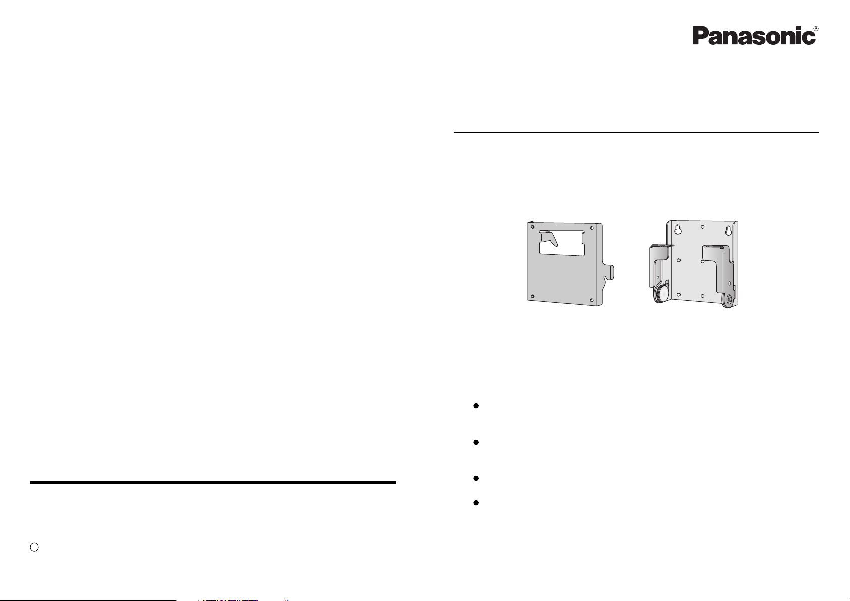
Wall-hanging bracket
for Combination LCD TV / DVD Player
and LCD TV
Model No. TY-WK22LR1W
Matsushita Electric Industrial Co., Ltd.
Web Site : http://www.panasonic.co.jp/global/
C 2004 Matsushita Electric Industrial Co., Ltd. All rights reserved.
MBS0504A0 (MBS)
Thank you very much for purchasing the wall-hanging bracket for the
Panasonic Combination LCD TV / DVD Player and LCD TV.
Please perform installation work correctly after carefully reading this
installation manual and the operation manual for the Combination LCD
TV / DVD Player and LCD TV.
After installation work is complete, please give this installation manual to
the customer so they can read it and keep for future reference.
(It may be needed for maintenance or when moving.)
Retain all removed parts. They may become necessary when returning
to the original installation condition.
Caution:This bracket intended for use only with Panasonic LCD TV Model
TC-22LH30 / TX-22LX2 / TC-20LA2 / TX-20LA2 / TC-20LB30 / TX-20LB30
/ TC-17LA2 / TX-17LX2 / TC-14LA2 series and TC-20LA2D / TC-17LA2D
/ TC-14LA2D.
Use with other apparatus is capable of resulting in instability causing
possible injury.
TQZH566
Page 2
Safety Precautions
To prevent injury to the user and others and to prevent damage to property, directions
that must be followed are explained as shown below.
The following displays categorize the degree of danger when mishandled.
WARNING
Possibility of serious injury and even death
when mishandled.
Be sure to follow
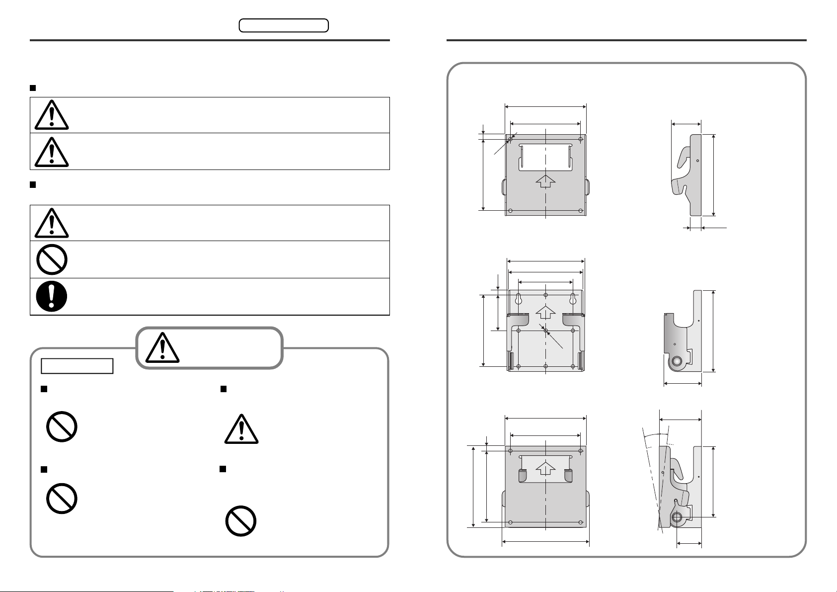
Wall-hanging bracket dimesional drawings
Wall-hanging bracket A (Main unit side)
116
7
100
41.8
CAUTION
Directions that must be followed are explained using the following symbols.
(Examples of graphical symbols are shown below.)
This symbol indicates that the direction must be followed with caution.
This symbol indicates that the direction is prohibited.
This symbol indicates that the direction must always be followed.
Possibility of injury or damage to surrounding
property.
WARNING
Installation
Installation to be performed by
certified personnel only.
Inadequate installation may
cause the Combination LCD
TV / DVD Player and LCD TV
Prohibited
to fall, resulting in bodily injury.
Be aware of safety factors con-
cerning the mounting strength.
Insufficient strength may
cause the Combination LCD
TV / DVD Player and LCD TV
to fall, resulting in bodily injury.
5
Φ
100
t=1.6
Wall-hanging bracket B (Wall side)
112 .3
106.3
8.5
48.5
97
Overall assembly
7100
78.5
116
100
Φ
5
t=2.0
10°
114
14.8
114
58.4
60
5°
Do not install where tolerance is weak.
If the tolerance of the mounting location is weak, the
Combination LCD TV / DVD
Prohibited
Player and LCD TV may fall
resulting in bodily injury.
Do not hang from the Combina-
tion LCD TV / DVD Player and
LCD TV, use a stepladder.
the Combination LCD TV/
DVD Player and LCD TV may
become damaged or it may
Prohibited
fall, causing bodily injury.
35
99.5
[ Unit: mm ]
114
124
2 19
Page 3
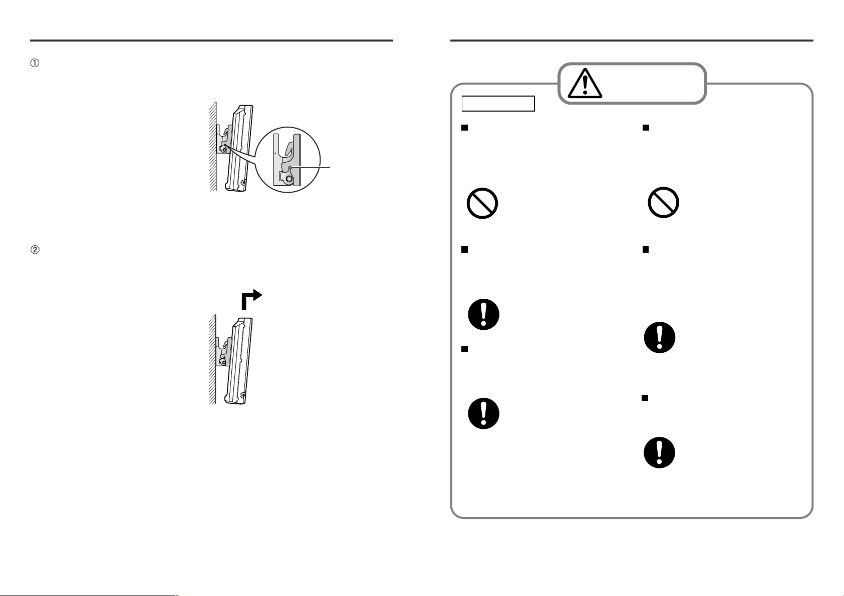
LCD television removal
Remove the angle fastening 2
screws mounted to the left and right
sides of the wall-hanging bracket.
CAUTION
Installation
While lifting the Combination LCD TV
/ DVD Player and LCD TV, pull it
away from the wall and remove.
Fixing screw
Do not install in humid or dusty
areas, or where the Combination
LCD TV / DVD Player and LCD TV
may be exposed to lampblack,
steam or heat.
This may affect the Combination LCD TV / DVD Player
and LCD TV, and may cause
Prohibited
At least two persons should per-
form installation and removal of
the Combination LCD TV / DVD
Player and LCD TV unit.
Always remove the wall-hanging
bracket when removing the Combination LCD TV / DVD Player and
LCD TV.
•Take caution when removing for
repairs, etc.
fire or electric shock.
Dropping the Combination
LCD TV / DVD Player and
LCD TV may result in injury.
Injury may result when
accidentally hitting the
projected parts.
Do not install with the Combina-
tion LCD TV / DVD Player and
LCD TV facing downward, on its
side, or upside down.
Heat may build up within
the Combination LCD TV
/ DVD Player and LCD TV,
Prohibited
Ensure there is a space of at least
5 cm between the Combination
LCD TV / DVD Player and LCD TV
body and other objects at the top
and bottom, at least 10 cm at the
sides and 4 cm at the back.
Make sure there is sufficient air
circulation so that the ambient temperature does not exceed 35 °C.
causing fire as a result.
Vent holes are located on
the rear of the Combination
LCD TV / DVD Player and
LCD TV. Blocking these
holes may result in fire.
Heat may build up within
the Combination LCDTV/
DVD Player and LCD TV,
causing fire as a result.
318
Page 4

Components
Before starting installation, first check that all components have been supplied.
Wall-hanging bracket A
(main unit side)
( 1 )
Bracket mounting screw
(main unit side)
( 4 )
(M4 × 12 mm)
Wall-hanging bracket B
(wall side)
( 1 )
Angle fixing screw
(for main unit side / wall side fixing)
( 2 )
Precautions for installation work
The wall-hanging bracket is for installing an Combination LCD TV / DVD
Player and LCD TV on a vertical wall for viewing. Do not use it for installing in
any other place than on a vertical wall.
The stand must be removed from the Combination LCD TV / DVD Player and
LCD TV before the wall-hanging bracket may be mounted. Before starting work,
be sure to turn the power off and unplug the AC adapter power supply plug.
Install using techniques that suit the structure and materials of the installation
location.
Use commercially available M4 bolts suitable for the wall material (wood,
steel frame, concrete etc.) as the screws for fastening to the wall.
Allow sufficient strength for safety.
The weight of the Combination LCD TV / DVD Player and LCD TV is
approximately 4-10 kg.
When mounting on a wall, perform work so that it can withstand the weight of
the television and so that the bracket will not come loose from vibration, etc.
Reinforce the bracket if the mounting section strength is insufficient.
The television may fall if the installation is insufficient or if the screws are loose.
Check to make sure there are no electrical wires within the wall.
Use the supplied cable clampers to fix cables. Never fix cables using staples.
2 Wall-hanging bracket fastening.
To prevent the main unit from falling, fix the main unit using fixing screws
(2 units) from both sides. If the fixing holes of the brackets do not align,
installation is incorrect. Check the installation again and fix so that screw
holes are aligned.
Fixing screw
Caution
Be sure to mount the angle fastening screws on the left and right to
prevent the Combination LCD TV / DVD Player and LCD TV from falling.
3 Install at the desired angle.
Position the LCD TV wall-hanging bracket at the desired angle from 5°
upsweep to 10° downsweep.
Set the angle by adjusting the notches of wall-hanging bracket B (wall
side) and the concave section of wall-hanging bracket A (main unit side) to
the desired angle.
Caution
Do not apply force to the bracket in an attempt to make it exceed
the setting angle of 5° upsweep to 10° downsweep. Damage to or
malfunction of the LCD TV may result.
174
Page 5

Installation procedure
(Cont'd)
Attaching the Combination LCD TV / DVD Player and
4
LCD TV to the wall-hanging bracket B (wall side)
1 Installing on the wall.
Put the fixing screws on the fixing holes located on wall-hanging brackets
B (wall side).
Fixing hole
Fixing screws
Hang the Combination LCD TV / DVD Player and LCD TV on wallhanging bracket B.
Wall-hanging
Wall-hanging
bracket A
bracket B
(Wall side)
Holding part
Fixing
Screw
To guarantee Combination LCD TV / DVD Player and LCD TV performance
and prevent problems, do not install in locations such as the following:
Near sprinklers or heat / smoke detectors
Where there is a risk of vibration or impact
Near high voltage wires or motors
Near sources of magnetism, heat, water vapor or soot
Exposed to air from heating equipment
Ensure air can flow around the Combination LCD TV / DVD Player and LCD
TV so that the temperature does not exceed 35 °C.
Otherwise malfunction may occur due to the build-up of heat inside the
Combination LCD TV / DVD Player and LCD TV.
About the installation location
Be sure to explain the following points to the customer:
The Combination LCD TV / DVD Player and LCD TV is best viewed directly
from the front.
Avoid areas where the florescent lighting reflects on the Combination LCD
TV / DVD Player and LCD TV surface. Although vertical angles can be
adjusted, the hanging bracket does not move horizontally.
For the main power supply plug, use an outlet that can be easily reached
by hand. Also make sure that the television is at a height where the power
supply switch can be easily operated, and that it is at a distance within the
remote control range (approximately 6 m from the front).
For the installation height, do not exceed the range of the connection cords
(AC adapter, antenna, etc.).
Be sure to install in a location where the AC adapter is not suspended and
where it can be placed on the floor, table, etc.
Install where there are no objects within 20 cm below the Combination
LCD TV / DVD Player and LCD TV.
Check the installation height, depth, wall structure, etc., before performing
installation work.
Caution
To prevent damage to the wall, make sure that the main unit is
securely mounted on the notches of wall-hanging bracket B (wall
side) before letting go of the main unit. Installation of the television on the wall should be performed by at least two people.
516
Page 6

Installation procedure
Check the strength of the intended installation position
1
The weight of the Combination LCD TV / DVD Player and LCD TV installed on
the wall-hanging bracket is approximately 4-10 kg.
Referring to the dimension drawing below, check the wall strength at the 4
mounting positions. If strength is insufficient, provide reinforcement.
112 .3
106.3
8.5
48.5
97
Wall mounting holes ( × 4)
Mounting wall-hanging bracket B
2
Wall-hanging bracket B
78.5
Φ
5
[ Unit: mm ]
For the TC-14LA2D
Before starting the mounting procedure, remove the AC adapter and connection
cable attached to the LCD TV. Be sure to perform mounting correctly and securely.
1 Remove the photo stand.
Remove the 3 screws.
Slowly pull off the photo stand in the
upward direction.
2 Mount wall-hanging bracket A.
Align the holes in wall-hanging bracket A with the screw holes in the LCD TV.
Using a level, determine the installation
position where the mounting is horizontal, and
mark the wall.
Fix wall-hanging bracket B (wall side) using
commercially available M4 4 screws.
If bolts or nuts must be embedded in the wall beforehand, such as with a
concrete wall, determine the hole positions by aligning with the actual wallhanging bracket B, or by referring to the dimension drawing, and embed
anchors of approximately 4 mm diameter.
Note:
Use commercially available M4 screws suitable for the mounting surface
material as the screws for fastening to the wall.
Securely fasten with the 4 bracket
mounting screws A (M4 × 12 mm).
Note:
Store the photo stand and screws carefully in case they are required in future.
When connecting cables to the LCD TV, certain cables may touch the wall.
Avoid putting any weight on the cables when they touch the wall.
156
Page 7

Installation procedure
(Cont'd)
Installation procedure
(Cont'd)
For the TC-14LA2 / TC-14LA2C
Before starting the mounting procedure, remove the AC adapter and connection
cable attached to the LCD TV. Be sure to perform mounting correctly and securely.
1 Remove the stand cover.
Remove the screw.
Slowly pull off the stand cover in the
upward direction.
2 Remove the TV stand.
Remove the 4 screws.
Pull the TV stand slightly towards
yourself, and remove it in the upward
direction.
3 Mount wall-hanging bracket A.
Align the holes in wall-hanging bracket A with the screw holes in the LCD TV.
Preparation of television
3
For the TC-22LH30 / TC-22LH30C
TX-22LX2 / TX-22LX2F / TX-22LX2P
Before starting the mounting procedure, remove the connection cable attached to
the LCD TV. Be sure to perform mounting correctly and securely.
1 Remove the stand cover.
Remove the screw.
Slowly pull off the stand cover in the
upward direction.
2 Remove the TV stand.
Remove the 4 screws.
Remove the TV stand.
Securely fasten with the 4 bracket
mounting screws A (M4 × 12 mm).
Note:
Store the stand, stand cover and screws
carefully in case they are required in future.
When connecting cables to the LCD TV, certain cables may touch the wall.
Avoid putting any weight on the cables when they touch the wall.
3 Mount wall-hanging bracket A.
Align the holes in wall-hanging bracket A with the screw holes in the LCD TV.
Securely fasten with the 4 bracket
mounting screws A (M4 × 12 mm).
Note:
Store the stand, stand cover and screws
carefully in case they are required in future.
When connecting cables to the LCD TV, certain cables may touch the wall.
Avoid putting any weight on the cables when they touch the wall.
714
Page 8

DC IN 15V
PS TBMU428
AUDIO
VIDEO S-VIDEO
R
RL
L
Y
P
B
P
R
1
2
AUDIO
COMPONENT VIDEO INPUT
INPUT
VIDEO
Installation procedure
(Cont'd)
For the TC-20LA2 / TC-20LA2C / TC-20LA2H / TC-20LA2G
TX-20LA2 / TX-20LA2F / TX-20LA2P / TX-20LA2M
TX-20LA2A / TX-20LA2T / TX-20LA2X
Before starting the mounting procedure, remove the connection cable attached to
the LCD TV. Be sure to perform mounting correctly and securely.
1 Remove the TV stand.
Remove the 4 screws.
Remove the TV stand.
2 Mount wall-hanging bracket A.
Align the holes in wall-hanging bracket A with the screw holes in the LCD TV.
For the TC-17LA2D
Before starting the mounting procedure, remove the AC adapter and connection
cable attached to the LCD TV. Be sure to perform mounting correctly and securely.
1 Remove the photo stand.
Remove the 4 screws.
Remove the photo stand.
2 Remove the photo stand mounting bracket.
Remove the 2 screws.
Remove the photo stand mounting bracket.
3 Mount wall-hanging bracket A.
Align the holes in wall-hanging bracket A with the screw holes in the LCD TV.
Securely fasten with the 4 bracket
mounting screws A (M4 × 12 mm).
Note:
Store the stand and screws carefully in
case they are required in future.
When connecting cables to the LCD TV, certain cables may touch the wall.
Avoid putting any weight on the cables when they touch the wall.
Securely fasten with the 4 bracket
mounting screws A (M4 × 12 mm).
Note:
Store the photo stand, photo stand mounting bracket and screws carefully in case
they are required in future.
Back of the TV
Antenna
Terminal
The antenna cable may be bent and
damaged near the connector if the
F-Adapter is used for connection.
In such situations, remove the FAdapter and connect the antenna cable
F-Adapter
directly.
When connecting cables to the LCD TV, certain cables may touch the wall.
Avoid putting any weight on the cables when they touch the wall.
138
Page 9

Installation procedure
(Cont'd)
For the TX-17LX2 / TX-17LX2F / TX-17LX2P
Before starting the mounting procedure, remove the AC adapter and connection
cable attached to the LCD TV. Be sure to perform mounting correctly and securely.
1 Remove the stand cover.
Remove the 2 screws.
Slowly pull off the stand cover in the
upward direction.
2 Remove the TV stand.
Remove the 4 screws.
Remove the TV stand.
For the TC-20LA2D
Before starting the mounting procedure, remove the connection cable attached to
the LCD TV. Be sure to perform mounting correctly and securely.
1 Remove the photo stand.
Remove the 4 screws.
Remove the photo stand.
2 Remove the photo stand mounting bracket.
Remove the 2 screws.
Remove the photo stand mounting bracket.
3 Mount wall-hanging bracket A.
Align the holes in wall-hanging bracket A with the screw holes in the LCD TV.
Securely fasten with the 4 bracket
mounting screws A (M4 × 12 mm).
Note:
Store the stand, stand cover and screws
carefully in case they are required in future.
When connecting cables to the LCD TV, certain cables may touch the wall.
Avoid putting any weight on the cables when they touch the wall.
3 Mount wall-hanging bracket A.
Align the holes in wall-hanging bracket A with the screw holes in the LCD TV.
Securely fasten with the 4 bracket
mounting screws A (M4 × 12 mm).
Note:
Store the photo stand, photo stand mounting bracket and screws carefully in case
they are required in future.
When connecting cables to the LCD TV, certain cables may touch the wall.
Avoid putting any weight on the cables when they touch the wall.
912
Page 10

DC IN 15V
PS TBMU428
AUDIO
VIDEO S-VIDEO
R
RL
L
Y
P
B
P
R
1
2
AUDIO
COMPONENT VIDEO INPUT
INPUT
VIDEO
Installation procedure
(Cont'd)
For the TC-20LB30 / TC-20LB30C / TC-20LB30H / TC-20LB30G
TX-20LB30F / TX-20LB30P / TX-20LB30M / TX-20LB30A
TX-20LB30T / TX-20LB30X
Before starting the mounting procedure, remove the connection cable attached to
the LCD TV. Be sure to perform mounting correctly and securely.
1 Remove the stand cover.
Remove the AC cord from the
clamper attached to the stand cover.
Remove the 2 screws.
Slowly pull off the stand cover in the
upward direction.
2 Remove the TV stand.
Remove the 2 screws.
Remove the TV stand.
For the TC-17LA2 / TC-17LA2C
Before starting the mounting procedure, remove the AC adapter and connection
cable attached to the LCD TV. Be sure to perform mounting correctly and securely.
1 Remove the TV stand.
Remove the 4 screws.
Remove the TV stand.
2 Mount wall-hanging bracket A.
Align the holes in wall-hanging bracket A with the screw holes in the LCD TV.
Securely fasten with the 4 bracket
mounting screws A (M4 × 12 mm).
3 Mount wall-hanging bracket A.
Align the holes in wall-hanging bracket A with the screw holes in the LCD TV.
Securely fasten with the 4 bracket
mounting screws A (M4 × 12 mm).
Note:
Store the stand, stand cover and screws
carefully in case they are required in future.
When connecting cables to the LCD TV, certain cables may touch the wall.
Avoid putting any weight on the cables when they touch the wall.
Note:
Store the stand and screws carefully in
case they are required in future.
Back of the TV
Antenna
Terminal
The antenna cable may be bent and
damaged near the connector if the
F-Adapter is used for connection.
In such situations, remove the FAdapter and connect the antenna cable
F-Adapter
directly.
When connecting cables to the LCD TV, certain cables may touch the wall.
Avoid putting any weight on the cables when they touch the wall.
1110
 Loading...