

Panasonic TX-D1F64 User Manual [en, es, fr]
Operating instructions
Mode d’empioi
Manual de Instrucciones
Multi-Scan Color Monitor
MODEL TX-D1F64
Designed for
Microsoft*
Windows*98
Panasonic*’
These Operating instructions are for units for saie and use in
the United States oi America and Canada only.
Read these Instructions completely before operating this display moniitor.
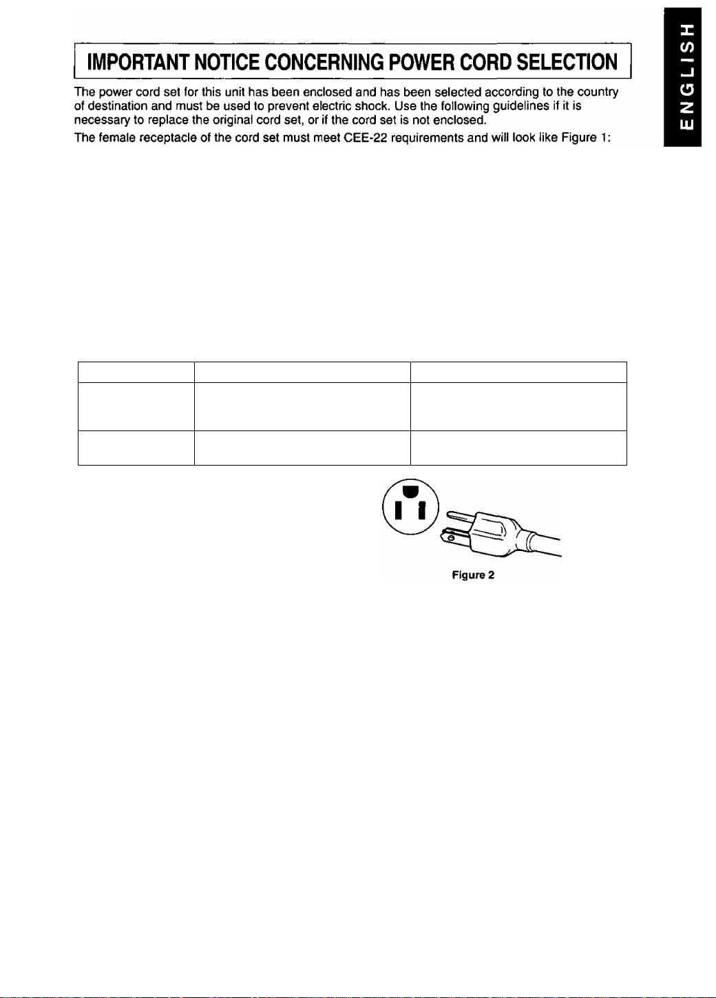
For the United States and Canada:
In the United States and Canada the male plug is a NEMA 5-15 style {Figure 2) and is UL listed and
CSA labelled. For units which are mounted on a desk or table, type SVT or SJT cord sets may be
used. For units which sit on the floor, only SJT type cord sets may be used. The cord set must be
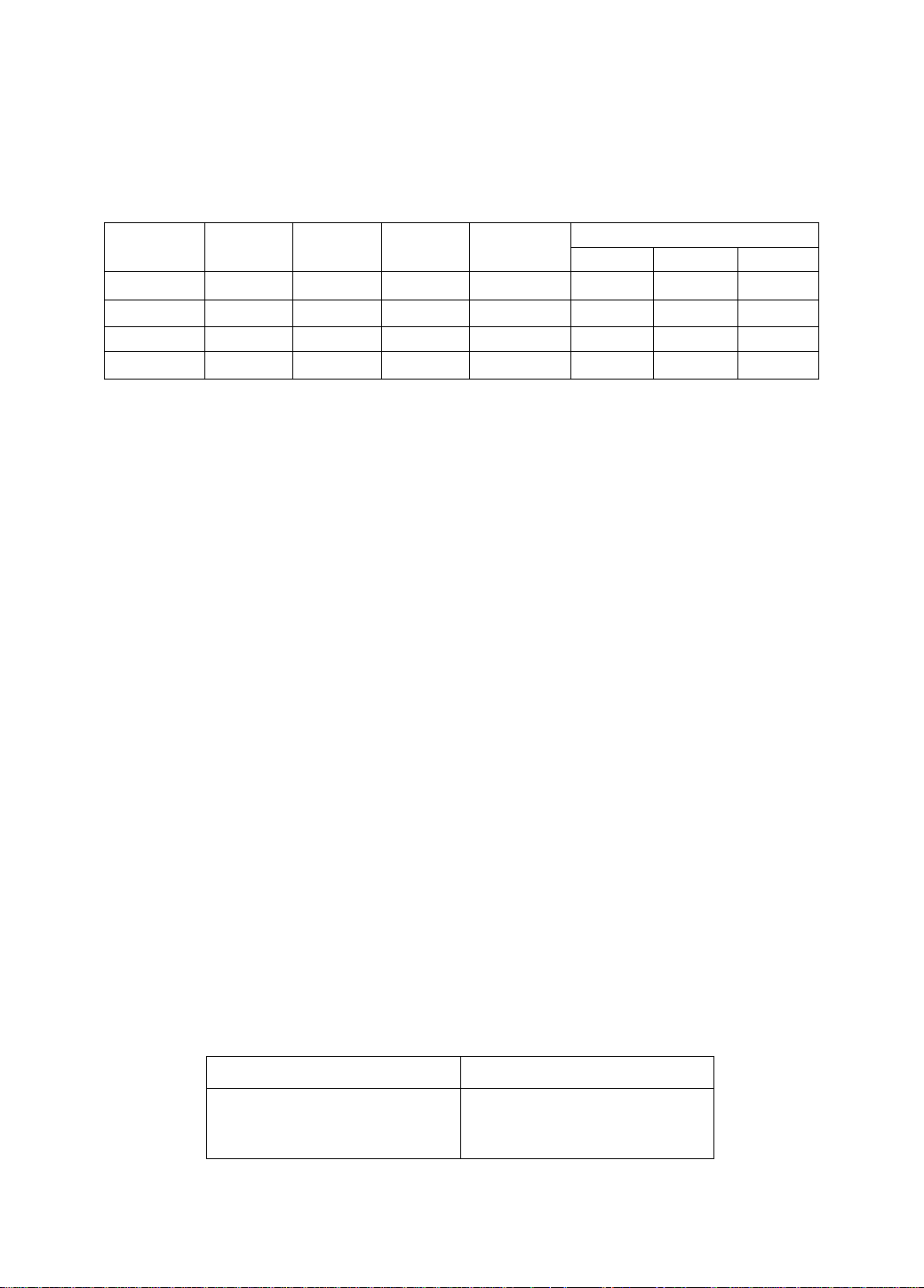
selected according to the current rating for your unit. Please consult Table A for the selection criteria
for power cords used in the United States and Canada. {The cord set is marked with its Cord Type.)
For European Countries:
in Europe you must use a cord set which Is appropriate for the receptacles in your country.
The cord set is HAR-Certified, and the mark 4 HAR k will appear on the outer sheath, or on
the insulation of one of the inner conductors.
If you have any questions concerning the proper power cord to use, please consult the dealer from
whom you have purchased your unit.
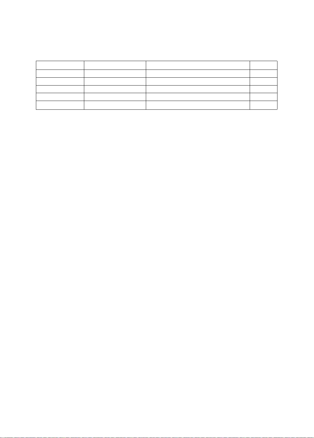
Table A
Cord Type Size of Conductors in Cord Maximum Current Rating of Unit
18 AWG 10 Amps
SJT 16 AWG 12 Amps
12 Amps
10 Amps
12 Amps
•iVT
14 AWG
18 AWG
17 AWG
(^¡5
Figure 1
Federal Communications Commission Requirements
This equipment has been tested and found to comply with the limits for Class B digital devices,
pursuant to Part 15 of the FCC Rules. These limits are designed to provide reasonable protection
against harmful interference in a residential installation. This equipment generates, uses, and can
radiate radio frequency energy and, if not installed and used in accordance with the instructions, may
cause harmful interference to radio communications. However, there is no guarantee that interference
will not occur in a particular installation. If this equipment does cause harmful interference to radio or
television reception, which can be determined by turning the equipment off and on, the user is
encouraged to try to correct the interference by one or more of the following measures:
- Reorient or relocate the receiving antenna,
- Increase the separation between the equipment and receiver.
- Connect the equipment into an outlet on a circuit different from that to which the receiver is
connected.
- Consult the dealer or an experienced radio / TV technician for help.
FCC Warning:
To assure continued FCC compliance, the user must use the provided grounded power supply
cord and shielded interface cable with bonded ferrite cores. If BNC cable is going to be used,
use only shielded BNC {5) cable. Also, any unauthorized changes or modifications to this moni
tor would void the user’s authority to operate this device.
NOTE FCC Class B Complied : Up to Mode 1,600 x 1,200 at 115 kHz max. and
1,800 X 1,440 at 105 kHz max. Horizontal frequency.
CE Conformity
This device complies with the requirements of the EEC directive 89 / 336 / EEC as amended
by 92 / 31 / EEC and 93 / 68 / EEC Art. 5 with regard to “Electromagnetic compatibility" and
C€
73 / 23 / EEC as amended by 93 / 68 / EEC Art. 13 with regard to “ Safety".
Required item
EMI
ESD
RADIATED RF
TRANSIENT F/B
LINE HARMONICS
#1 :Satisfies standards with no problems in performance and reliability.
#2 : Effects may appear temporarily on the screen but there will be no problem in reliability.
#3 : There is fear of the product breaking down.
#4 : If a signal cable other than that specified is used, it may be the cause of electromagnetic
interference to peripheral devices.
To assure continued CE compliance the user must use the provided 1.5 m shielded video signal
cable with bonded ferrite cores at both ends of the cable.
Handle correctly in accordance with the instruction manual.
EMI: Electromagnetic Interference ESD : Electrostatic Discharge
RF ; Radio Frequency F / B : Fast Burst
Relative to Standard Value Relative to those Exceeding Standard Value
#1
#2
#1
#1
#1
#3
#3
#3
-
ENERGY STAR
As an Energy Star® partner, Panasonic Document Imaging Company has determined that this
product meets the Energy Star® guidelines for energy efficiency.
Remarks
#4
-
-
-
-
Notice for Germany
NOTE:
• For ergonomic reasons, it is recommend not to use blue characters on a dark background. Doing so may
produce insufficient contrast that could lead to eye strain.
German
HINWEIS:
• Aus ergonomischen Gründen wird empfohlen, die Grundfarbe Blau nicht auf dunklem Untergrund zu
verwenden (schlechte Erkennbarkeut, Augenbelastung bei zu geringem Zeichenkontrast wäre die Folge).
Notice for Japan
This is a Class B product based on the standard of the Voluntary Control Council for
Interference from Information Technology Equipment (VCCI). If this is used near a radio or
television receiver in a domestic environment, it may cause radio interference. Install and use
the equipment according to the instruction manual.
Japanese

A A I Danger
To avoid the risk of severe electrical shock including death, do not remove
covers (or back) of monitor. No user serviceabie parts are inside. Refer servicing
to qualified service personnel.
A A I Warnings
To prevent risk of electric shock and possible fire:
Never piace any object on the monitor, AC Power cord, or cause the cords to make
sharp bends, or otherwise do anything that can affect the integrity of the cords.
Always remove the line cord from the socket by holding the plug, not the cord.
Do not place anything containing any iiquid (even a wet or damp cioth) on the
monitor as the introduction of fluids can create an eiectrical hazard. Do not
expose the monitor to rain or moisture.
Do not piace the monitor with less than the recommended clearance (see
Precautions, 1 Installation Page 4). Do not block the ventilation openings with
anything. Do not insert any objects into the ventiiation openings.
Customer’s Record
The serial number of this product is printed on its back cover label.
Note this serial number in the space provided and retain this booklet as a permanent record of
your purchase to aid in identification of the unit in the event of theft or loss.
Model number: TX-D1F64___________________
Serial number:
Table of Contents
IMPORTANT NOTICE CONCERNING POWER CORD SELECTION....................1
Federal Communications Commission Requirements...........................................1
CE Conformity.........................................................................................................2
Energy Star®........................................................................................................2
Notice for Germany.................................................................................................2
Notice for Japan......................................................................................................2
Danger.....................................................................................................................3
Warnings.................................................................................................................3
Customer’s Record................................................................................................. 3
Table of Contents....................................................................................................3
Precautions 1) Installation...................................................................................... 4
Precautions 2) Usage.............................................................................................4
Precautions 3) Product Care...................................................................................4
Features................................................................................................................. 5
Specifications......................................................................................................... 6
Installation.............................................................................................................. 7
Pin Assignment...................................................................................................... 8
External View......................................................................................................... 8
Operation................................................................................................................ 9
Operation procedure.............................................................................................. 9
Adjustments.......................................................................................................... 10
Power Management System................................................................................ 14
Memories.............................................................................................................. 14
Timing Specifications........................................................................................... 15
Troubleshooting.................................................................................................... 16
Technical Support................................................................................................ 16
ALL PRODUCT / BRAND NAMES ARE TRADEMARKS OR REGISTERED TRADEMARKS OF THE RESPECTIVE HOLDERS.
© 1999 MATSUSHITA ELECTRIC INDUSTRIAL CO„ LTD.

Precautions
1) Installation
• Install the monitor in a well ventilated place. Avoid exposing to direct sunlight, a
heater, or any other heat source. Heat will adversely affect the cabinets and the parts
inside.
• Position the display unit so that the holes in the cabinet will not be blocked during use.
• Keep the display unit away from the kitchen, bathroom, washing machine, or other
sources of exposed to water, steam or moisture.
• In order to use the display unit safely, use only the supplied AC Power cord. The AC
Power cord must be used with a properly grounded and polarized power supply
socket. The AC Power cord supplied is for the USA (UL) and Canada (CSA) for use
with the display unit. For use in other countries, make sure the AC Power cord meets
the safety standards of the country.
• Place the AC Power cord where it will not be subject to stress.
• Use only Panasonic provided accessories or the exact equivalent.
2) Usage
• Pulling on the AC Power cord or VGA Signal Cable can damage the display unit
(monitor) and can cause the unit to fall and possibly cause personal injury.
• Receiving trouble.
If there is a television set or other display unit nearby, keep your display unit as far
away from it as possible. Mutual interference can cause image distortion or noise.
• Long exposure to rubber or vinyl products can stain the cabinet.
• Keep the monitor from physical shock when moving. Be careful of the Cathode Ray
Tube (CRT).
• Do not place anything on the monitor.
• Also take good care of the AC Power cord:
Do not place any objects on the AC Power cord. Do not attempt to extend, shorten or
tie it into a knot.
3) Product Care
• Prior to cleaning your display unit, disconnect the AC Power cord and the VGA Signal
Cable or BNC Cable from the display unit.
• Use a clean, soft, dry cloth to clean the outside of the monitor or the CRT surface.
If the monitor or CRT surface is very dirty, wet a clean, soft cloth with neutral
detergent (such as dishwashing detergent) and water, squeeze it tight untii almost dry,
wipe the monitor or CRT surface with it, and finish by wiping with a clean dry cloth. Do
not use any solvents.
• Do not rub or strike the monitor with anything hard or harsh as this may scratch, mar
or damage the monitor permanentiy.
• Do not use a chemical duster or polish-cleaner because it can adversely affect the unit
and peel the paint coat.

1) High Image Quality in a Package
• Panasonic Panasync/Pro PI lOi with a CRT 21" (20.0" / 50.8 cm Viewable Image Size) has image quality
that has to be seen to be believed. It has a 0.25 mm ultra fine dot pitch and up to 1,600 x 1,200 at 92 Hz /
1,800 X 1,440 at 70 Hz maximum resolution. The Panasync/Pro P110i produces sharp saturated color
images with High Contrast and Brightness that can be viewed over a wide viewing angle.
• Combined with optimized dynamic focusing circuitry, the CRT has improved beam landing accuracy, focus,
convergence and lower raster distortion than a typical 21-inch CRT. This gives the Panasync/Pro P110i a
sharper, more uniform focus, especially in the corners of the screen, traditionally a focus problem area.
Crystal Pigment Phosphors and Advanced Invar Mask provide increased Contrast and Brightness.
• Panasync/Pro digital multi-scan 30 kHz to 117 kHz* Horizontal and 50 Hz to 180 Hz Vertical scanning
frequencies can be automatically scanned. Eight timing selections have been preset at the factory and 20
user programmable selections are provided.
2) Crystal Pigment Phosphors
• Crystal Pigment Phosphors provide increased brightness and contrast for the PllOi creating crisp colorful
images. Each grain of Crystal Pigment Phosphor is covered with a filter material of the same color to titter
external light.
3) Advanced INVAR Shadow Mask and Dark tint
• The CRT also features an Advanced INVAR Shadow Mask, which is manufactured with an improved material
and designed to be positioned closer to the screen glass. When combined with the Dark tint of the screen,
this results in a 10% overall increase in brightness, improved purity due to less environmental movement,
and better overall color uniformity.
4) New DQ-DAF^“ Electron Gun with Super New OLF
• The new DQ-DAF (Double-Quadruple Dynamic Astigmatism and Focus) electron gun reduces the
degradation of the screen focus, realizing higher resolution. In addition, the super new OLF (Overlapping
Field) main lens for the PI lOi creates a smaller spot size which contributes to sharper images.
5) Digital adjustment using on-screen Menu (OSM)
• The On-Screen Menu is available in five (5) languages. English, French, German, Italian or Spanish can be
selected. Custom adjustments can be made quickly and easily through the On-Screen Menu utilizing four
buttons on the front panel. The On-Screen Menu may be positioned in one of six locations and color in one
of six colors on the Display Screen. A Self-Test On-Screen display is provided with no signal input or an
Error On-Screen Menu if the Horizontal or Vertical Scanning frequencies are outside the specified range.
6) The PllOi is Plug & Play
• VESA* DDC™ 1 / 2B compatible (Video Electronics Standards Association Display Data Channel). This
allows the PllOi to inform a compatible host of its capabilities that meet the Microsoft* / Intel® Plug & Play
Definition used by Windows* 95 and Windows® 98.
7) Self-test menu
• The display unit can be checked via the self-test menu displayed on the screen. This menu can be accessed
without a computer.
8) Environmentally Friendly
• The PllOi has a VESA® DPMS™ power management circuit. When used with a DPMS™ compatible
graphics card, the power consumption of the PllOi can be reduced. This product conforms to the
Energy Star* program.
• All plastic parts are recyclable.
• Meets MPR II, TCO’92 and carries the CE mark.
9) Color Adjusting Function
• The White Reference Color Temperature is 9300 К -i- 8 MPCD, 7500 K, 6500 K, 5000 K. 9300 К + 27 MPCD
or User Color which can be selected to adjust the red, green and blue signals of the monitor to match its
image to the output of a color printer.
10) Ergonomic Design
• Tilt & Swivel base with 90-degree pan to right or left and tilt angle of 13 degrees up a 3 degrees down.
• Advanced Anti-Glare, anti-Refection, and Anti-Static screen coating.
FCC Class B Complied : Up to Mode 1,600 x 1,200 at 115 kHz max. and 1,800 x 1,440 at 105 kHz max.
Horizontal frequency.
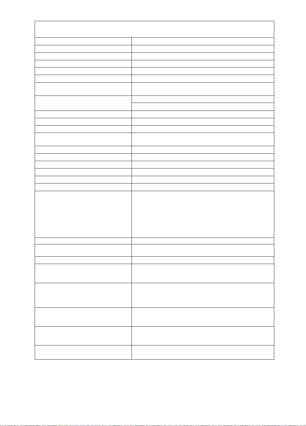
Specifications
CRT Size
Dot-pitch
Phosphor/ Glass
Surface treatment
Input signals Video signaling RGB analog
Signal level
Sync, signal
Frequency Range Horizontal Frequency : 30.0 kHz to 117.0 kHz*
Preset mode 1 preset and 7 reservation (See page 15)
Video Maximum Pixel Clock 250.0 MHz (typ.)
Resolution 1,600 dots (H) X1,200 lines (V) at 92 Hz, 1,800 dots (H) x l ,440 lines (V) at 70 Hz*
Viewable Image Size Factory preset
(H X V, Diagonal) Full scan (Typical)
Display Color
Connectors Video Signal
Power supply
Input power
Power consumption
Controls Front
On screen display Contrast, Brightness, Size & Pos. (Zoom, H. Position, H. Size,
Tilt / swivel
Dimensions (W x H x D)
Weight (monitor only)
Approvals
Standard
Environmental conditions Operating Temperature 5 to 35 ’C(41 to 95 T)
Storage Temperature -20 to -r-60 *C (-4 to 140 °F)
Windows® 95 / 98 Plug & Play VESA® DDC™ 1 / 2B meets Windows® 95 / 98 Plug & Play
Note;
• The on-screen image may flicker if the display is operated with the Vertical freq. under 60 Hz.
* FCC Class B Complied : Up to Mode 1,600 x 1,200 at 115 kHz max. and 1,800 x 1,440 at 105 kHz max. Horizontal
** Depends on signal timing used, see page 15.
*** Number of colors depends on the Video Board used, memory installed, and RAMDAC (Random Access Memory
Digital to Analog Converter),
Specifications and design are subject to change without notice.
This product may be subject to export control regulations. Weight and dimensions shown are approximate.
frequency,
21" CRT (20.0" / 50.8 cm Viewable Image Size) Flat Square
0.25 mm (Horizontal: 0.217mm / Vertical: 0.132mm)
RGB medium short persistence (Hi-EU RED), Crystal Pigment / Dark tint
B-AGRAS (Anti-Glare, antÍ-ReflectÍve and Anti-Static) Coat
0.7 Vp-p (without sync, signal), 1.0 Vp-p (with sync, signal)
H / V separation (TTL level), H / V composition (TTL level),
Sync.-on-green
Vertical Frequency : 50.0 Hz to 180.0 Hz
15.59" X11.69", 19.5" Diagonal **
15.98" X 11.97", 20.0" Diagonal ”
Analog input, unlimited number of colors ***
15 pin mini D-Sub connector (female pins), BNC x 5
CEE-22 type 3-pin connector
100 to 240 V AC (50 or 60Hz)
148 W typ. / < 10 W stand-by, < 3 W sleep mode (See page 14)
Power ON / OFF, [0, H, H, H] keys
V. Position, V. Size), Geometry (V. Pincushion, Side Pin. Bal.,
Trapezoid, Parallelogram, Top Comer, Bottom Corner, S-Curve 1,
S-Curve 2), Rotation (Tilt), Color Temp. (9300K + 8 MPCD, 7500
K, 6500 K, 5000 K, 9300 K -t- 27 MPCD, User), Recall, Video Level
(0.7 V /1 V), H. Moire, V. Moire, H.Convergence, V.Convergence,
Linearity-C, Linearity-E, Language, OSD Position, Degauss, Signal,
Self-Test menu
13° up, 3° down, 90° each to right and left
19.6" X 18.8" X 19.5"
(498 mm x 477.5 mm x 494.5 mm)
27.0 kg (59.5 lbs)
UL1950, CSA 22.2 No.950, TÜV / GS, CE / CISPR 22-B (EN55022),
NORDIC, FCC Class B, DHHS, HC, IC-B, VCCI Class B,
MPR II, TCO'92, Energy StarI®, ISO 9241-3 (Ergonomics) / -8 (Colors)
1 detachable signal cable for VGA, SVGA
1 detachable AC power supply cord
Tilt & Swivel base attached
Operating Instructions, Warranty card
Humidity 5 to 90% (no condensation)
Altitude 10,000 ft
Humidity 5 to 90% (no condensation)
Altitude 40,000 ft
Requirements
Installation
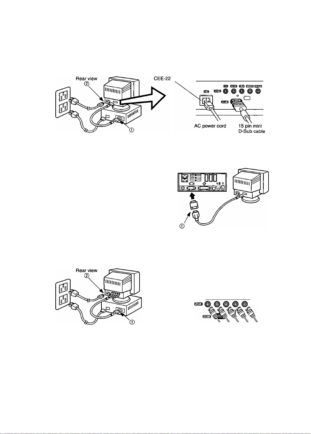
^ Connecting Procedures
Turn off your computer.
Connect the signal and power connectors as shown below.
Turn the monitor on, then turn on the computer.
A. IBM PS / 2 or PC / AT compatible models
© Connect the supplied 15 pin mini D-Sub cable to the monitor’s Port A.
Then connect the other end of the supplied 15 pin mini D-Sub cable to the computer’s corresponding
15 pin mini D-Sub video connector.
@ First connect the supplied AC power cord to the CEE-22 connector on the rear of the monitor.
Then connect the other end of the AC power cord to a grounded power outlet.
B. Apple computer
® Connect the supplied 15 pin mini D-Sub cable to the
monitor’s Port A.
Then connect the other end of the supplied 15 pin mini
D-Sub cable to a UNIMAC-82D MAC adapter and the other
end of the MAC adapter the computers to the computer’s
corresponding 15 pin mini D-Sub video connector.
@ First connect the supplied AC power cord to the CEE-22
connector on the rear of the monitor. Then connect the
other end of the AC power cord to a grounded power
outlet.
Panasonic MAC adapter
If your need an adapter and one is not provided by your dealer, call 1-800 PANASYS (1-800-726-2797).
— Caution;-------------------------------------------------------------------------------------------------------------------
To prevent the cable from coming loose, the cable connectors must be securely fastened with screws.
C. BNC connector signal computer
® Connect the BNC signal cable (Not supplied) BNC connectors to the monitor’s Port B.
Then connect the other end of the BNC cable, usually a 15 pin mini D-Sub connector, to the computer’s
corresponding 15 pin mini D-Sub video connector.
(D First connect the supplied AC power cord to the CEE-22 connector on the rear of the monitor.
Then connect the other end of the AC power cord to a grounded power outlet.
Blue video signal
Green video signal
or sync on green
Red video signal
Horizontal sync signal or
composite sync signal
Vertical sync
signal
Î5ËÔ> CREEM ffCuFl fVBVNCl
4 Connection of AC Power Supply
If the AC power supply voltage is in the range 100 to 240 V, either 50 Hz or 60 Hz frequency can be used.
There is no AC 100 V / 240 V selector switch as selection is automatic.
— Precaution:------------------------------------------------------------------------------------------------------------------------
* In order to use the display unit safely, use a power cord that is properly grounded.
• AC plug cords for the following countries must be used as follows:
U.S.A
................
For use in other countries, make sure that the AC cord meets the safety standards of each country.
UL Canada
.............
CSA
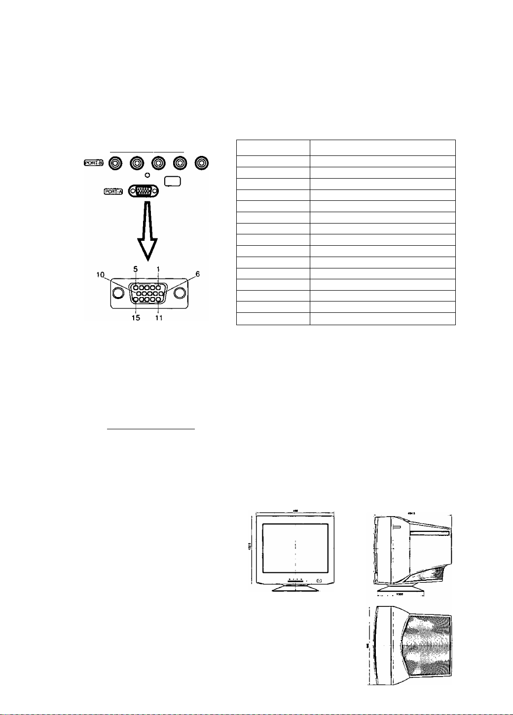
Pin Assignment
Follow the instructions below to connect the PllOi to a computer.
A. Signal connector: 15 pin mini D-Sub (PS / 2 or PC / AT compatible model)
Connect the signal cable to the 15 pin mini D-Sub connector on the display unit.
B. Signal connector: 15 pin D-Sub (Apple computer)
Convert a MAC 15 pin D-Sub connector to a 15 pin mini D-Sub connector using a Panasonic MAC
adapter, and connect it to the 15 pin mini D-Sub connector on the display unit.
< REAR PANEL >
(repI (greei^ [beuei |h-syhc1 rvsvMct
C. Signal connector: BNC connector
Pin assignments of 15 pin mini D-Sub connector
Pin number
1
2
3 Blue video signal
4
5 Ground*
6
7
8 Ground for Blue video signal
9 Unused
10 Ground
11
12
13
14
15 SCL* (Data Clock)
*: “VESA”s Display Data Channel (DDC) Standard
Sync on green system
Connect the signal cable to RED, GREEN (sync
ongreen) and BLUE BNC connectors.
Red video signal
Green video signal
Ground
Ground for Red video signal
Ground for Green video signal
Ground
SDA* (Bi-directional Data)
Horizontal sync, signal
Vertical sync, signal
Signal name
[REOl IGREENl (BLUEl (H-SYNCl (V-SyHC)
O
□
External View
Dimensions
Width
Height
Depth
Base diameter
Height without stand: 432.5 mm (17.0")
*an / Tilt range
Up
Down
Left, right : 90 degrees each
13 degrees
: 498 mm (19.6")
: 477.5 mm (18.8")
: 494.5 mm (19.5")
:<l>300 mm (<t>11.8")
3 degrees
Composite sync system
Connect the signal cable to RED, GREEN, BLUE
and H-SYNC (H / V composite) BNC connectors.
Separate sync system
Connect the signal cable to RED, GREEN, BLUE
and H-SYNC and V-SYNC BNC connectors.
Note : If your computer’s video output is over
110 MHz, it is recommended that it be
used with the BNC connectors.
••To
U
8
Operation
Basic operation
m
<1 0
□
3E
Displays main menu.
Exits menus.
Selects menu item.
To scroll through menu item.
To adjust level of selected item.
Menu screen
The functions that can be adjusted for this unit are displayed as icons.
1) Press the d] key to return to the menu screen.
2) This is modified by pressing the 3 and B keys at the front.
3) Press the [2] key to enter the adjustment screen.
Et
o
-PI
a o
1=1
a
iO
s
[osdI*
Contrast
Rotation Color Temp
H. Moire V. Moire
Lineari ty-C Linearity-E
Brightness
Contrast
Degauss
Signal
Size & Pos.
Recall
H. Convergence
Language
Geometry
Video Level
V. Convergence
OSD
Position
Operation procedure
Horizontal position adjustment
1. Press the S key to display the menu.
2. Press the E key to select the Size & Pos. from
the menu screen.
Press the d] key to display the menu.
3. Press the ID key to select the H. Position.
4. Press the front 3 or B keys to reach the
desired condition.
5. Press the D] key to save the settings to memory
and complete the adjustments. Press the Q]
key once more to clear the menu screen.
CD < > 0
CD <] > 0
Q] < > 0
E < > 0
E < > 0
o
m S
p\
3
o
OliS
1^1 s
P\
H . Position
50
a ta B jOj 1X|:E]|
H. Position
70
3
o
m
jn
[B
Contrast
|s:f
-iii-
c:9
-k
7i
s ize & Pos
-ili-
Cf
7i
“✓ è
size & Pos
SI
Eli.
a
iO
m n
■ili
o
n
iO

Adjustments
Adjustments menu
3 Contrast
Adjust the screen contrast to match the brightness level in the room.
Pressing the [2] key toggles between brightness and contrast.
Direct operation]
Even if the menu screen does not appear, the contrast can be adjusted by pressing
the H or B key. If the 3 and B keys are pressed at the same time, the
maximum level (100) will be set.
Brightness ! Adjust the brightness to match the brightness level in the room so that the level
will be easy to see.
Pressing the [D key toggles between contrast and brightness.
Note; If the 3 and B keys are pressed at the same time on the Brightness
adjustment screen, the standard level (50) wilt be set.
Size & Pos. ! Press the {
2
} key to select the zoom / horizontal position / horizontal size / vertical
position / vertical size adjustments.
Press the (T| key to save the adjustment.
Zoom ! Both the horizontal and vertical size of the image can be adjusted at the same
time; however, the aspect ratio cannot be changed.
Press the 3 key to make the image smaller, the B key to make it larger.
H. Position ! The horizontal position of the image can be adjusted.
Press the 3 key to move it to the left, the B key to move it to the right.
H H. Size ! The horizontal size of the image can be adjusted.
Press the 3 key to make the image smaller, the B key to make it larger.
Note: Setting the image in the center of the screen to start will make the
adjustment easier.
V. Position ! The vertical position of the image can be adjusted.
Press the 3 key to make it downward, the B key to move it upward.
m V. Size ! The vertical size of the image can be adjusted.
Press the 3 key to make the image smaller, the B key to make it larger.
Note: Setting the image in the center of the screen to start will make the
adjustment easier.
1
) u Geometry : Press the [2] key to select the vertical pincushion / side pincushion balance I
trapezoid / parallelogram / Geometry 2 adjustments.
Press the Q] key to save the adjustment.
O V. Pincushion ! The image can be corrected for barrel distortion.
Press the 3 key to decrease the Pin / Barrel distortion of the image,
the B key to increase it.
n Side Pin. Bal. ! It is possible to adjust the side pincushion balance to the left and right.
Press the 3 key to expand to the left of the image, the B key to
expand it to the right.
f~\ Trapezoid !The image can be corrected for trapezoidal distortion.
___
bottom edge narrower.
Press the 3 key to make the top edge narrower, the B key to make the
/~7 Parallelogram iThe image can be corrected for parallelogram distortion.
Press the 3 key to collapse the parallelogram to the left, the B key
to collapse it to the right.
^ h Geometry 2 ; Press the B key to change the sub OSD screen.
Press the [H key to select the Top Corner / Bottom Corner / S-Curve 1 /
S-Curve 2 adjustments.
O Top Corner ! The image can be corrected for vertical pincushion distortion in the
top corner.
) I Bottom Corner ! The image can be corrected for vertical pincushion distortion in
the bottom corner.
51 S-Curve 1 ! The image can be corrected for vertical pincushion distortion in the S-
Curve 1.
10
L_i
52 S-Curve 2 ! The image can be corrected for vertical pincushion distortion in the S-
Curve 2.
I__I <^\
______
1

Adjustments (Continued)
Aijjustments menu
to Rotation : This control adjusts the evenness of the screen image relative to a horizontal line.
Note: If the 9 and B keys are pressed at the same time, the standard level
(50) will be set.
Color Temp It is possible to switch the whiteness of the image.
1) Press the 3 and B keys to select 1 (9300 K + 8 MPCD) / 2 (7500 K) /
3 (6500 K) / 4 (5000 K) / 5 (9300 K + 27 MPCD) / 6 (User).
2) [U will be displayed at the bottom right-hand side of the on-screen
panel when 6 (User color) has been selected. Press the [U key on
the front operation area to enter the User color adjustment screen.
User : It is possible to adjust the whiteness of the image to suit personal
preference.
1) Select R (red), G (green), B (blue) with the key.
2) Adjust the color to match personal preference with 3 and B keys.
* As user colors cannot be recalled, take note of the set values
beforehand.
*0 Recall
It is possible to return to the initial settings (the settings at the time of factory
shipment).
1) When the lU key (Yes) is pressed, the settings are recalled and the menu
screen returns. (Recall = return to initial settings (settings at time of factory
shipment))
2) When the [H key (No) is pressed, the menu screen returns without the settings
being recalled. (The settings return to what they were immediately before the
recall.)
If there are no operations performed for about 30 seconds, the screen goes off
without a recall.
5© Video Level : The video input signal level can be matched to the computer being used.
Either 0.7 V or 1.0 V can be selected with the ¡2} (0.7 V /1 V) key.
Use 0.7 V under normal condition.
Moire reduction Moire patterns are caused by interference of the CRT dot pitch and video
signal due to the resolution of the input signal, video pattern, etc., producing
patterns of horizontal stripes (Horizontal moire pattern) or vertical stripes
(Vertical moire pattern).
Caution:
If the moire reduction is overcorrected, the picture quality (for example focus,
vertical line stability, etc.) will sometimes be affected.
Keep this adjustment within the range in which the picture quality is not affected.
i# H. Moire
The moire correction circuit can be switched On and Off with the [T| key.
When the moire correction circuit is switched On with the [H (On / Off) key, the
adjustment screen menu appears.
Adjust with the 3 and B keys so that the striped moire pattern is in its optimum
condition.
^ V. Moire
The moire correction circuit can be switched On and Off with the [U key.
When the moire correction circuit is switched On with the [U (On / Off) key, the
adjustment screen menu appears.
Adjust with the 3 and B keys so that the striped moire pattern is in its optimum
condition.
11

Adjustments (Continued)
Adjustments menu
Convergence l convergence is affected by geomagnetism. Use this function when
convergence error occurs after moving the monitor or changing the screen
angle.
These convergence adjustments should be made after monitor operation has
stabilized.
Inihij H.ConvergsnC© ; Horizontal convergence of the image (color fringing) can be adjusted.
Press {2} key to toggle between H.Convergence and V.Convergence.
Note: If the H and E keys are pressed at the same time on the
H.Convergence adjustment screen, the standard level (50) will
be set.
Press the B key to move red to the right and blue to the left.
Press the 3 key to move red to the left and blue to the right.
l^J V.ConV6rg6nC6 I Vertical convergence of the image (color fringing) can be adjusted.
Press [H key to toggle between V.Convergence and H.Convergence.
Note: If the 3 and B keys are pressed at the same time on the
V.Convergence adjustment screen, the standard level (50) will
be set.
Press the B key to move red downwards and blue upwards.
Press the 3 key to move red upwards and blue downwards.
H Linearity-C
H Linearity-E
The image can be adjusted for vertical linearity in the center.
Press H] key toggle between Linearity-C and Linearity-E.
Note: It the 3 and B keys are pressed at the same time on the Linearity-C
adjustment screen, the standard level will be set.
Press the B key to make the center linearity narrower.
Press the 3 key to make the center linearity wider.
The image can be adjusted for vertical linearity in the edge.
Press d] key toggle between Linearity-E and Linearity-C.
Note: It the 3 and B keys are pressed at the same time on the Linearity-E
adjustment screen, the standard level will be set.
Press the B key to make the bottom linearity wider.
Press the 3 key to make the top linearity wider.
Language: The language of the On-Screen Display can be selected from among
German, French, English, Italian and Spanish.
Select with the 3 or B key.
fòs5k OSD Position
F\ Degauss
It is possible to adjust the position and color that the on-screen panel
is to be displayed. The panel will rotate in a counter-clockwis direction
every time the d] key is pressed.
The screen color layout can be changed by holding down the dl key
and pressing the 3 key.
Six different color layouts are available.
Use this function to reduce the irregular colors in the image. The degaussing
operates for approximately five seconds after selection.
Use this function when irregular colors occur in the image after moving the
monitor or the changing the screen angle.
Note: Be informed that a continued use of this function cannot result in a
satisfactory effect. (Try to keep an interval of about 30 minutes or so
between operations.)
12
Adjustments (Continued)
Adjustments menu
Signal ! Use the S and B keys to select either the rear panel input terminal port A
(Mini D-Sub type) or Port B (BNC) type.
This displays the input synchronization signal frequency.
Information on the input screen mode (resolution, horizontal and vertical
synchronization frequency) will be displayed on the display monitor. There are
occasions sometimes when some screen modes in use do not display any
resolution. Direct display allows this to be displayed on screen by pressing
the \J} key even when the menu screen is not displayed.
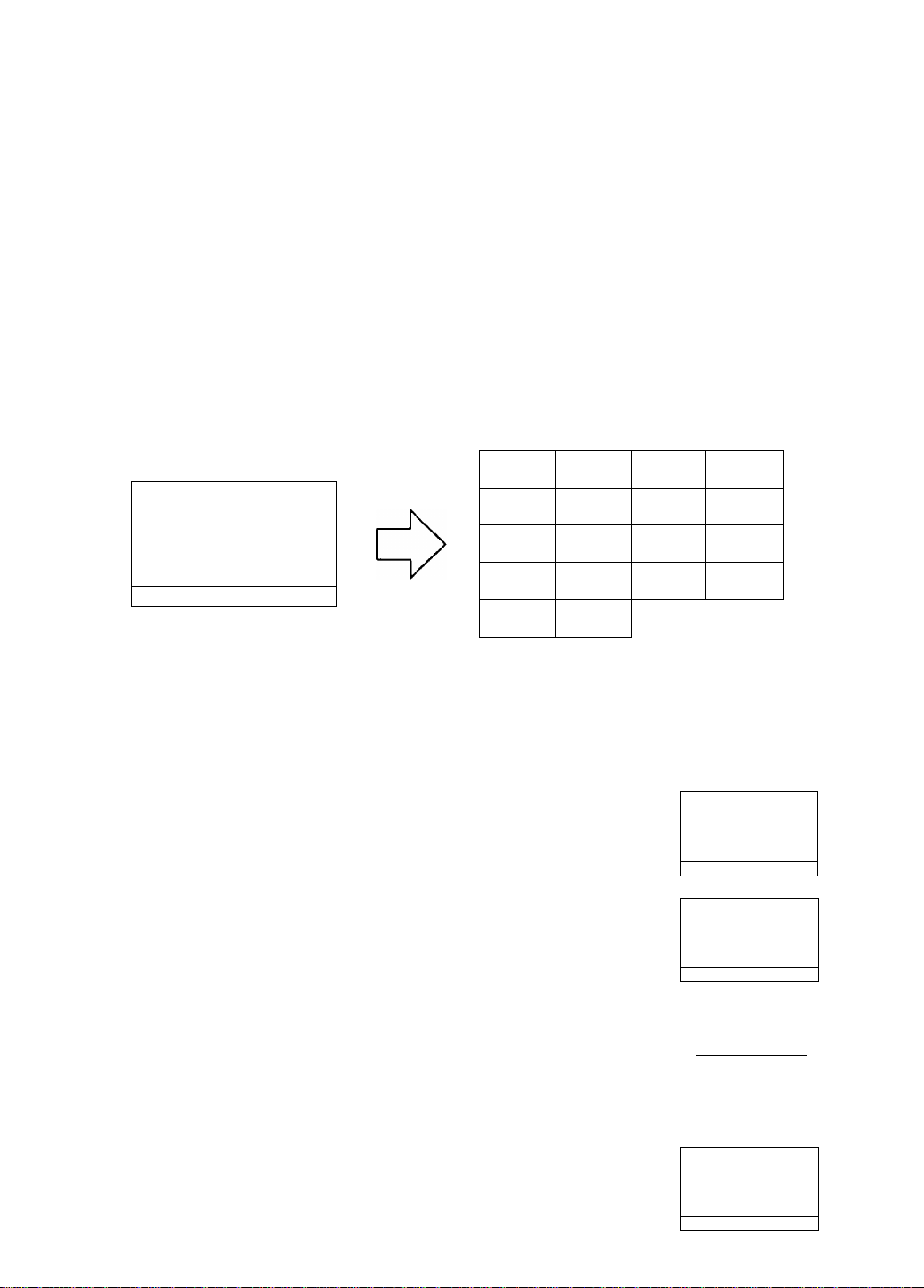
Self-Test menu (No Signal screen)
This display indicates that the monitor is operating normally. When one of the following
conditions occurs, press one of the 4 operation keys to call the appropriate display.
No Signal
fH — .— k H z
fV —.— Hz
Port ^ -0-
No signal (the computer is not connected,
the mains power to the computer is
disconnected or the input connector in
use may be deselected, see Page 13
Signal for instructions.)
Erro r
fH 1 1 9.0 kH z
fV 1 9 0.0 H z
Port ^ -O-
The horizontal or vertical sync, signal are
outside of the permitted range (the value of
the horizontal sync, signal will be displayed
in red and the value of the vertical sync,
signal will be displayed in white.)
13
Power Management System
This monitor conforms to the VESA® DPMS™ standard.
This function can suppress power consumption for the display unit.
The computer and video board being used must also conform to the VESA® DPMS™ standard.
‘ Consult the Operation Manuals for the hardware being used.
Modes change in response to input signals as indicated in the table below.
АРМ state
ON STATE
STAND-BY
SUSPEND Black out
OFF STATE
АРМ ; Advanced Power Management
Caution
Screen
status
Active
Black out
Black out Yellow
LED color
Green
Yellow
Yellow
Power
consumption
Normal
< 10 Watts < 3 sec. OFF
< 10 Watts < 3 sec. OFF
< 3 Watts
Recovery time
- ON
< 20 sec. OFF
Video
Input signals
Horizontal
ON
OFF ON
ON
OFF
Vertical
ON
OFF
OFF
• Turn the monitor off when it is not to be used for a long time.
• How to release the system from the power management function
1) Read the Operation Manuals for the hardware you are using.
2) Press one of the Ш, Э, B, Ш keys on the front panel.
The No Signal screen appears, and the monitor side power management function is
released (only in OFF STATE).
Memories
This display has two types of memory to store the data sets that control the on-screen
image. The first type of memory is the Preset Memory which is set by the factory. The
second type is the User Memory which is set by the user. Both memories store the
Horizontal Size, Vertical Size, Horizontal Position, Vertical Position, Vertical Pincushion,
Side Pincushion Balance, Trapezoid, Parallelogram, Top Corner, Bottom Corner, S-Curve
1, S-Curve 2, Video Level, Horizontal Moire, Vertical Moire, Linearity-C and Lineahty-E
adjustments of the displayed image.
14
Preset Memory
There are 1 preset (7 reservation) timings that are set by the factory. The preset timing will automatically size
and center the image with video boards which use these timings. Please see page 15 for Timing Specifications.
User Memory
• There are 20 memory locations that allow for user timing. The image size, position, geometric distortion are
adjusted by the user.
• If the User Memory is completely full, and a new set of data is saved, the oldest data set in the User Memory
will be deleted.
• The User Memory has priority over the Preset Memory.
• When the user timing is input, the Vertical, Horizontal frequencies and sync polarities of the signal are
compared with the previous data stored in memory. The input signal will be stored as a new data set if one of
its parameters is different from the previous stored one.
• The new input signal must have a frequency difference greater than that shown in the table below or a
different sync, polarity from that already stored. If the new timing data includes frequency changes greater
than those shown in the table below or sync, polarity changes, a new user memory setting will be stored. If the
frequency difference is smaller than that of the chart and the sync, polarities are the same, the existing
settings will be retained.
Horizontal frequency
Low 30 kHz ± 0.2 kHz
to
Hi 117 kHz ± 0.7 kHz
Please note if the timing does not meet the display specifications, the size and position adjustment may not
appear as desired. Be sure the horizontal and vertical timing are within the monitor specification range.
See page 15 for Timing Specifications, preset and reservation timing.
Vertical frequency
Low 50 Hz ± 0.3 Hz
to
Hi 180 Hz ± 1.1 Hz
 Loading...