

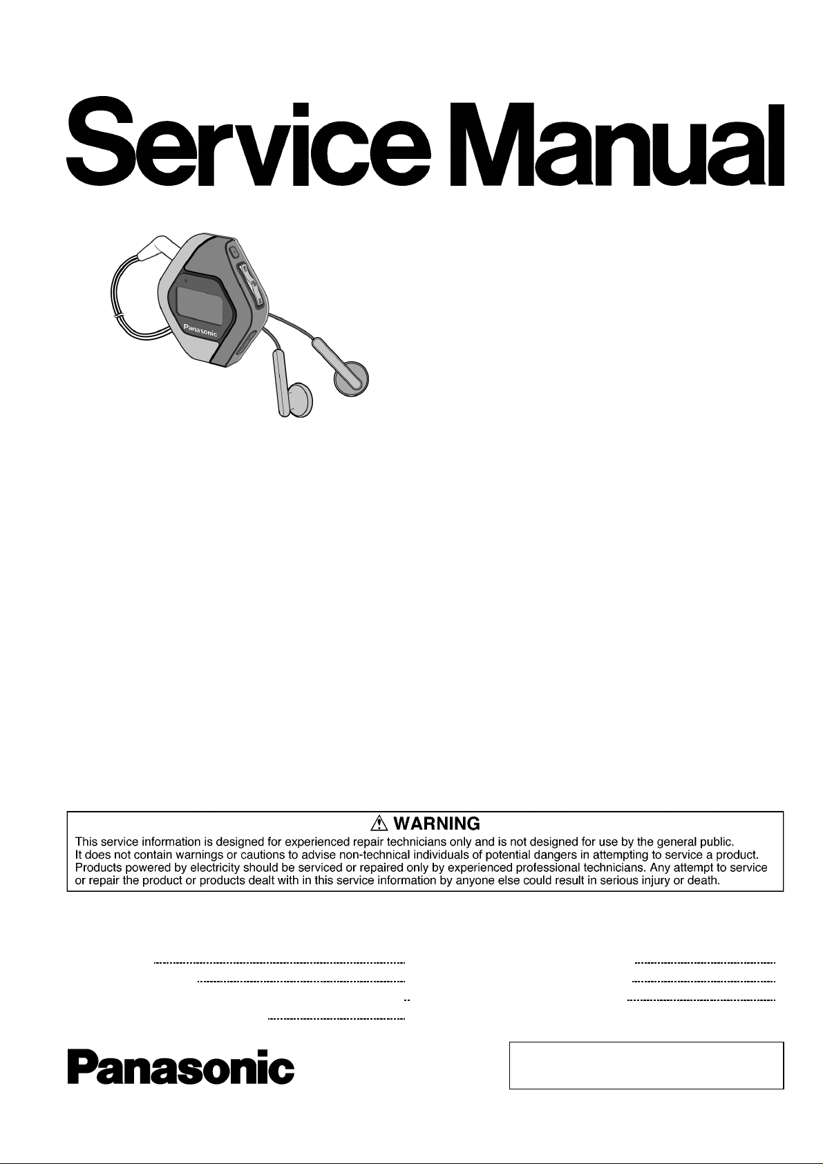
Panasonic SVMP-120-VE Service manual
AAA
A
A
y
Specifications
Memorysize: 512 MB
Supported sampling frequency: MP3; 32 kHz, 44.1 kHz, 48 kHz,
WMA; 8 kHz to 44.1 kHz
Supported bit-rates: MP3 8 kbps to 320 kbps (128
kbps is recommend) WMA 32
kbps to 192 kbps (96 kbps is
recommend)
No. ofchannels: Stereo, 2 channels (MUSIC, FM
RADIO) Mono, 1 channel (IC
RECORDER)
Frequencyresponse: 20Hz to 20,000Hz (+0dB, -6dB)
(MUSIC), 300 Hz to 4,300 Hz (IC
RECORDER,HQ mode)
Mic S/N: 30 dB (IC RECORDER,HQ mode)
Radio Frequencyrange (FM): 87.9 MHz to 107.9MHz (200kHz
steps),87.5 MHz to 108.0 MHz
(50/100 kHz steps),
Output: 4.5 mW + 4.5 mW (16Ω,M3jack)
TD0503015C2
Digital Audio Player
SV-MP120VE
Colour
(K)....................Black Type
Power supply: DC 1.5V (one alkaline LR03,
battery)
pproximate playtimes: 13 hours (MUSIC),
7 hours (FM RADIO)
pproximate recording times: 13 hours (IC RECORDER, HQ
mode)
7 hours (FM RADIO)
Maximum dimensions (WxHxD): 53.2x61.1x17.5mm
Mass: 41.7g with batter
30.4g without battery
· Specifications are subject to change without notice.
· The play times shown depend on operating conditions.
· Mass and dimensions are approximate.
· MB means one million bytes. Useable capacity may be less.
· This product is compat ible with the following character code. The
display may not appear correctly with o ther character codes.
CONTENTS
Page Page
1 Accessories
2 Location of Controls
3 Operation Checks and Component Replacement Procedures
3.1. Removal of the battery cover
2
3
4
4
3.2. Removal of the front cabinet
3.3. Removal of the SUB P.C.B.
3.4. Removal of the jack holder
© 2005 Matsushita Electric TAIWAN Industrial Co.,
Ltd. All rights reserved. Unauthorized copying and
distribution is a violation of law.
4
4
5
SV-MP120VE
3.5. Removal of the Main P.C.B. 5
3.6. Removal of the LCD Ass 馳
3.7. Removal of the LCD holder
3.8. Removal of the USB cover
3.9. Removal of the holder knob
3.10. Removal of the REC button and play button and volume
button and mode button
4 Instructions for Repair Service
5 Service Position
6 Service Mode
6.1. Checking Procedures for IC3 C2HBZG000008
6.2. Checking Procedures for Font table
7 Service Precautions
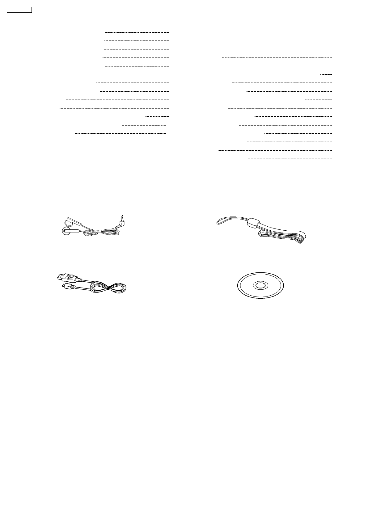
1 Accessories
· Stereo earphones
(L0BAB0000193) ............................................................. 1pc.
7.1. Install and Copy the software (DFU,firmware,font table)
5
5
6
6
6
8 Troubleshooting
9 Troubleshooting guide
7
8
10 Type Illustration of ICs, Transistor s and Diodes
9
11 Block Diagram
12 Schematic Diagram Notes
9
10
13 Schematic Diagram
10
14 Printed Circuit Board Diagram
15 Cabinet Parts Location
16 Packaging
17 Replacement Parts List
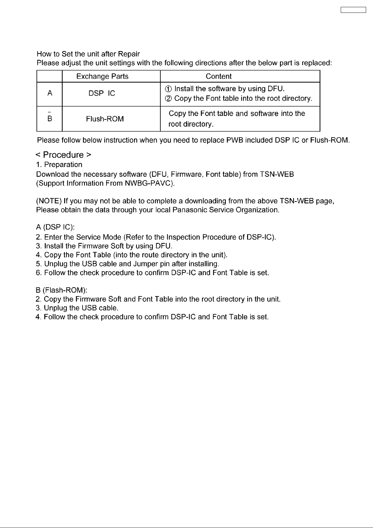
After replacing the main PCB and DSP IC (main
CPU),reinstall DFU and firmware,and copy font table
again.
7.2. Please contact to the service organization of the belonging
for the acquisition of data and obtain the software.
· Neck Strap
(VFC4028) .....................................................................1pc.
10
10
14
14
15
16
21
22
26
28
29
29
· USB Cable
(K1HA05AD0004)............. ................................................ 1pc.
· CD-ROM Driver
(RFET0002) .................................................................... 1pc.
2
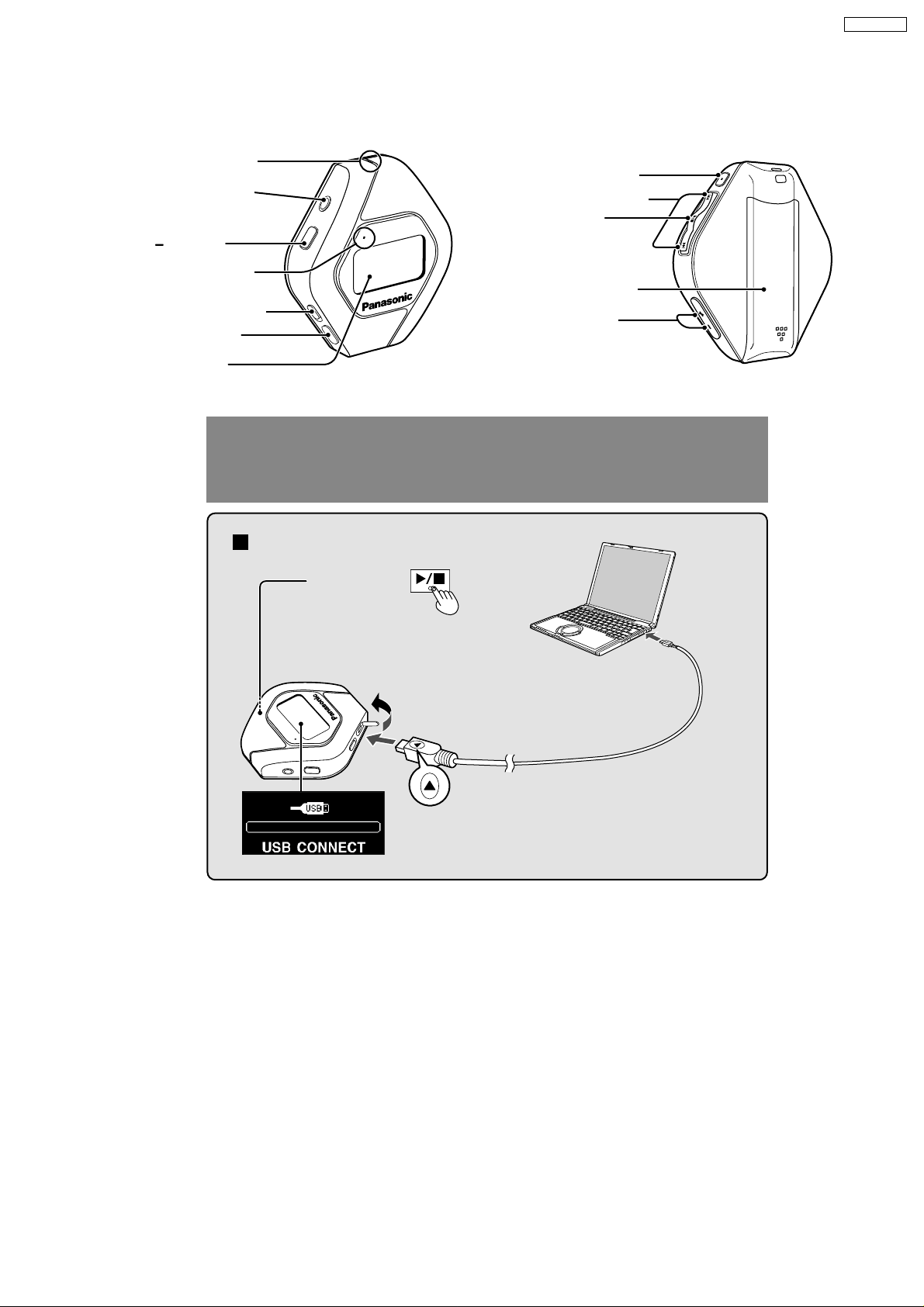
2 Location of Controls
Microphone
Earphones jack
(3.5 mm stereo)
MODE
Operation lamp
HOLD switch
USB port
Display
Connecting to a computer and
SV-MP120VE
(back)
REC/STOP
Skip/search
Turn on, off
(Press and hold)/
Play/Stop
Battery lid
Volume
Connection
Press
1
and hold
Turn the unit on.
(Wait until MODE
select display appears.)
2
downloading files
4
To USB
port
Small end to
player, large
end to PC
Insert so the arrow is
3
facing upwards.
3
SV-MP120VE
3 Operation Checks and
Component Replacement
Procedures
1. This section describes procedures for checking the
operation of the major printed circuit boards and replacing
the main components.
2. For reassembly after operation checks or replacement,
reverse the respective procedures special ressembly
procedures are described only when required.
3. Select item from the following index when checks or
replacement are required.
Contents
1. Checking for the main P.C.B.
2. Checking for the memory P.C.B.
3. Checking for the LCD ass’y.
4. Checking for the prevent electrostatic discharge.
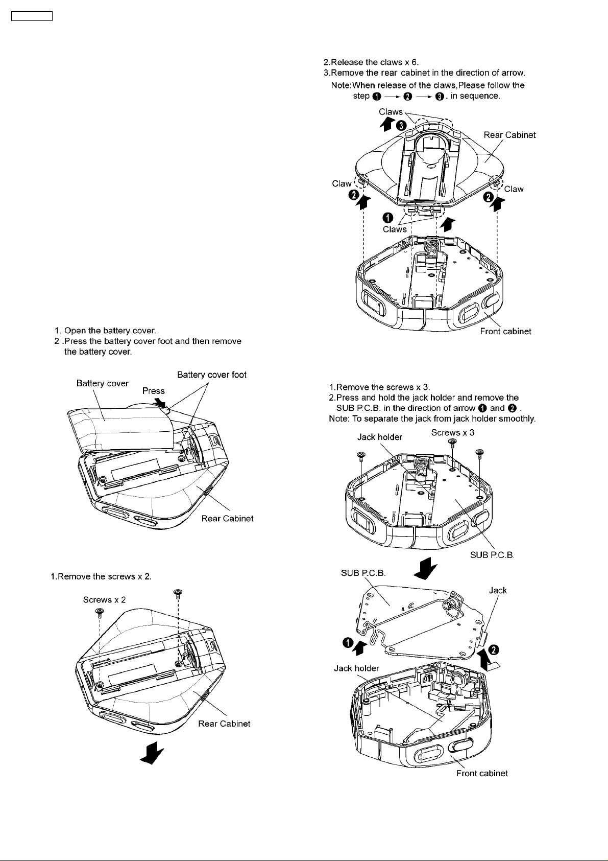
3.1. Removal of the battery cover
3.2. Removal of the front cabinet
3.3. Removal of the SUB P.C.B.
4
SV-MP120VE
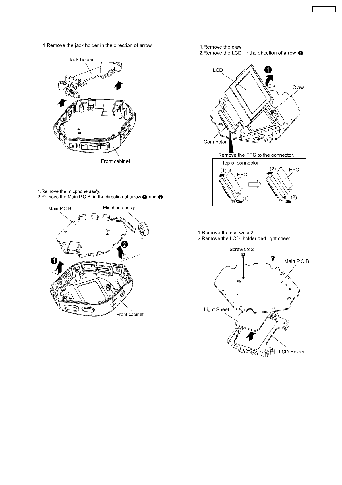
3.4. Removal of the jack holder
3.5. Removal of the Main P.C.B.
3.6. Removal of the LCD Ass’y
3.7. Removal of the LCD holder
5
SV-MP120VE
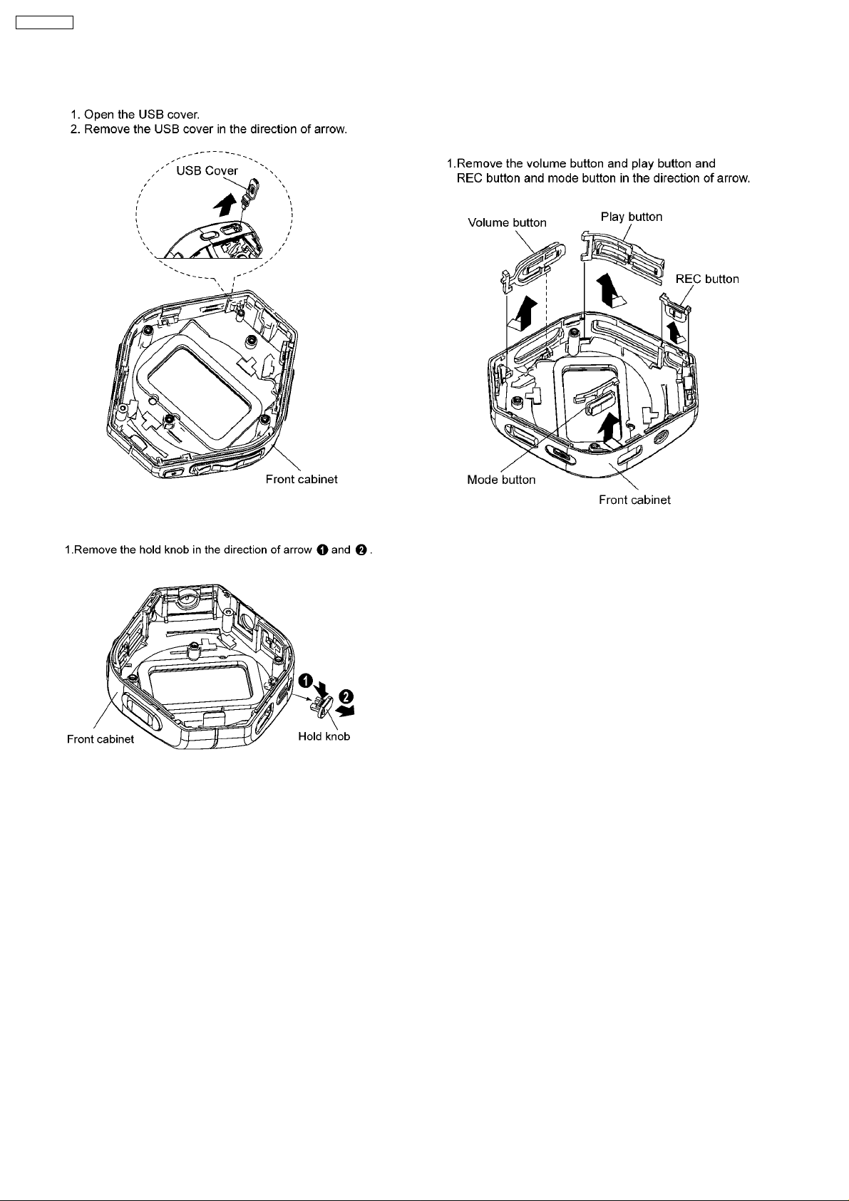
3.8. Removal of the USB cover
3.10. Removal of the REC button
and play button and volume
button and mode button
3.9. Removal of the holder knob
6
4 Instructions for Repair Service
SV-MP120VE
7
SV-MP120VE
5 Service Position
8
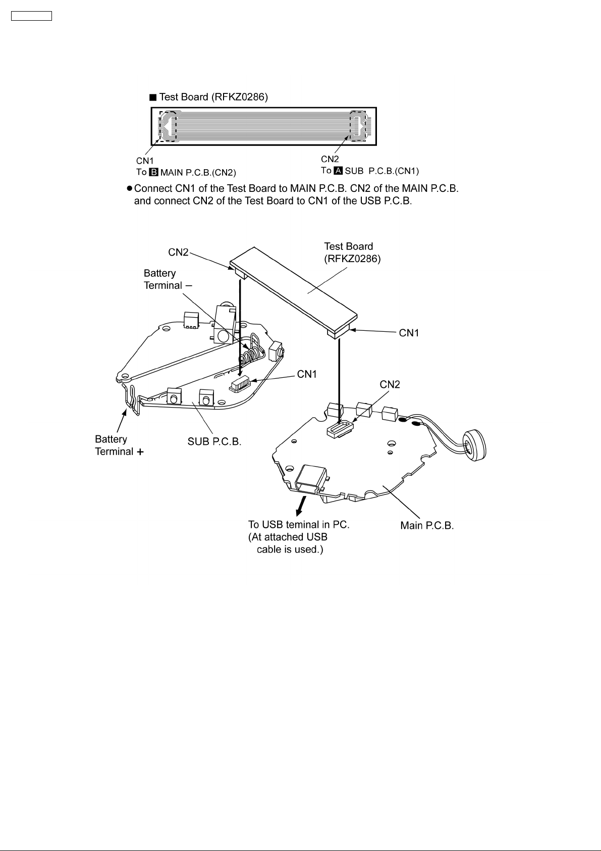
6 Service Mode
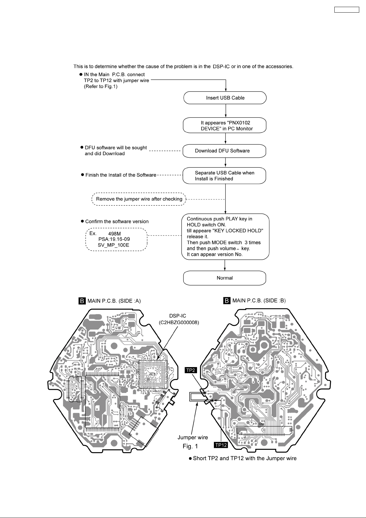
6.1. Checking Procedures for IC3 C2HBZG000008
SV-MP120VE
9
SV-MP120VE
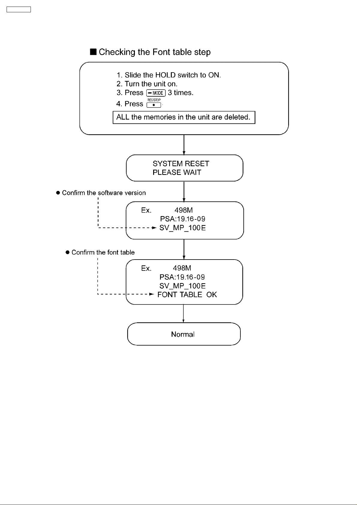
6.2. Checking Procedures for Font table
7 Service Precautions
7.1. Install and Copy the software (DFU,firmware,font table) After replacing
the main PCB and DSP IC (main CPU),reinstall DFU and firmware,and
copy font table again.
7.2. Please contact to the service organization of the belonging for the
acquisition of data and obtain the software.
10
 Loading...