

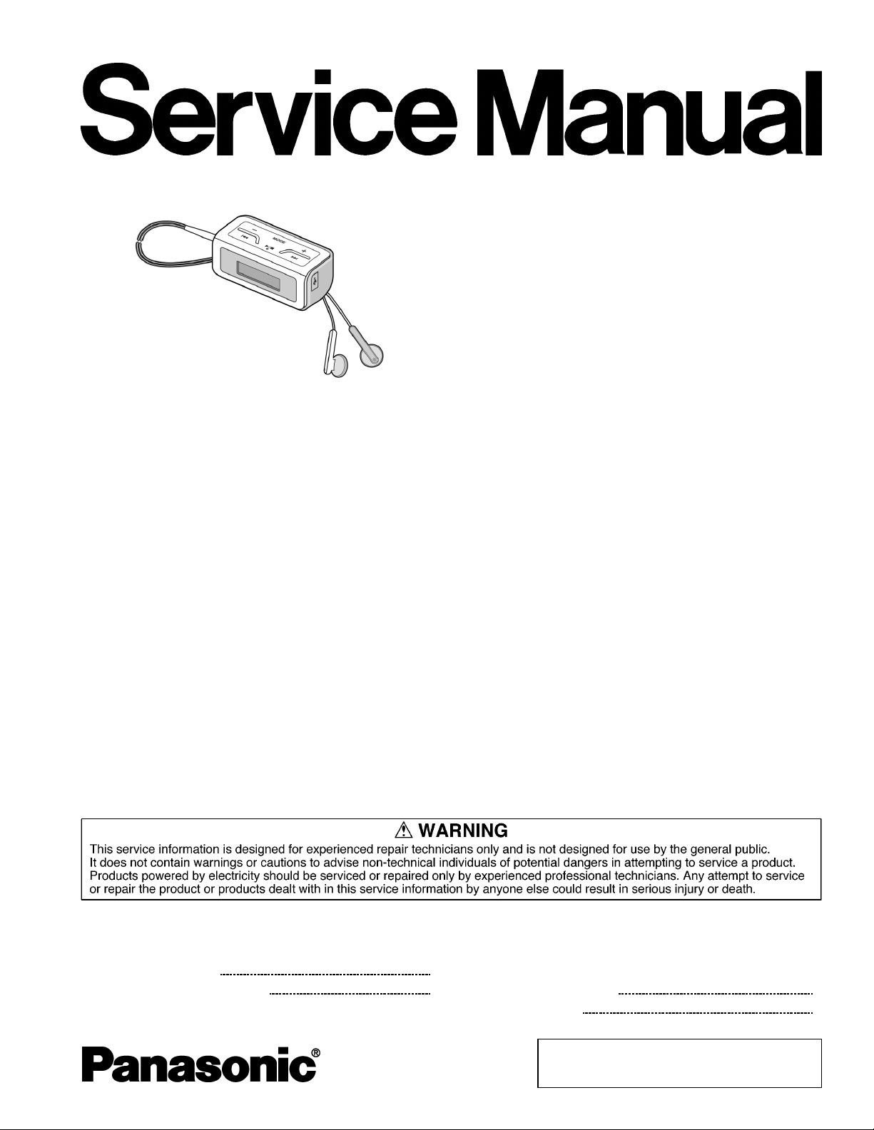
Panasonic SVMP-020-P Service manual
Specifications
Memory size:
Supported sampling frequency: MP3; 8 kHz to 48 kHz
WMA; 22.05 kHz, 32 kHz, 44.1
kHz and 48 kHz
Supported bit-rates:
No. of channels: Stereo, 2 channels
Frequency response: 20 Hz to 20,000 Hz (+ 0 dB, -6
Input (LINE):
Output: 3mW+3mW (16Ω ,3.5mm
Power supply:
Approximate play times: 80 hours
MP3; 8 kbps to 320 kbps (128
kbps is recommend)
WMA; 32 kbps to 192 kbps (96
kbps is recommend)
-14dB(0.2mV),3.5mm
(1/8” ) stereo mini jack
DC 1.5V (one alkaline battery)
2GB
dB)
TD0603004CE
A1
Digital Audio Player
SV-MP020P
Colour
(W)................... White Type
(A).................... Blue Type
Dimensions (W x H x D):
Mass: 51.5 g with battery (1.82 oz.)
· Specifications are subject to change without notice.
· The play time shown depends on operating conditions.
· Mass and dimensions are approximate.
· GB means one billion bytes. Usable capacity will be less.
· This product supports the following character codes. The display
may not appear correctly with other character codes.
· The play time shown is when the bit rate is 128 kpbs (MP3), EQ
SETTING (NORMAL), SURROUND (OFF), REMASTER (OFF),
volume is 12, the backlight is not used, the ambiend temperature
is 25°C and supplied alkaline battery is used.
Maximum: 62.5 mm x 28.5 mm x
29.0 mm
( 2 4/9” x 1 1/8 “ x 1 1/7” )
Cabinet: 62.0 mm x 28.5 mm x
28.5 mm
(27/16”x11/8“x11/8”)
28.0 g without battery (0.98 oz.)
CONTENTS
Page Page
1 System requirements
1.1. Caution for maintainment
2
2
1.2. During the maintainment, the right of the song data of the
customer as below
2 Safety Precaution
© 2006 Matsushita Electric TAIWAN Industrial Co.,
Ltd. All rights reserved. Unauthorized copying and
distribution is a violation of law.
2
2
SV-MP020P
2.1. Human body grounding 2
2.2. Work table grounding
3 Service Navigation
3.1. About Lead Free Solder (PbF)
4 Accessories
5 Location of Controls
6 Operation Checks and Component Replacement Procedures
6.1. Removal of the battery cover
6.2. Removal of the funtion button base
6.3. Removal of the front cabinet
6.4. Removal of the SUB P.C.B.
6.5. Removal of the main P.C.B.
6.6. Removal of the LCD Ass 馳
6.7. Removal of the LED P.C.B.
6.8. Removal of the LCD and sheet
6.9. Removal of the LCD piece and LCD holder
6.10. Removal of the holder piece
6.11. Removal of the USB cover
6.12. Removal of the hold knob
6.13. Removal of the battery terminal holder 8
2
3
3
3
4
5
5
5
6
6
6
7
7
7
7
8
8
8
6.14. Removal of the battery spring and spring holder
7 Service Position
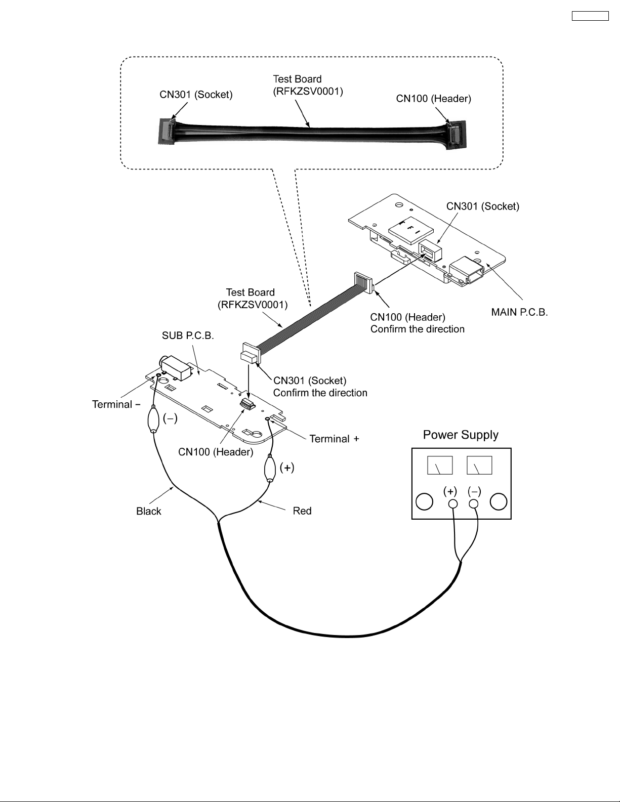
8 Service Mode
8.1. Update or install the firmware(When replace DSP IC and
Flash Memory IC, please re-install the firmware and font
table.)
8.2. Reset procedure
8.3. Checking the software version
9 Troubleshooting
10 Troubleshooting guide
11 Type Illustration of ICs, Transistors and Diodes
12 Block Diagram
13 Schematic Diagram Notes
14 Schematic Diagram
15 Printed Circuit Board Diagram
16 Cabinet Parts Location
17 Packaging
18 Replacement Parts List
8
9
10
10
11
11
12
12
13
14
19
20
24
26
27
28
1 System requirements
1.1. Caution for maintainment
1. Please make a copy before maintainment.
2. When update the software, please re-install the firmware.
3. When replace DSP IC and Flash Memory, please re-install
the firmware and font table.
2 Safety Precaution
2.1. Human body grounding
Use the anti-static wrist strap to discharge the static electricity
from your body.
2.2. Work table grounding
Put a conductive material (sheet) or steel sheet on the area
where the traverse deck (optical pick-up) is placed, and ground
the sheet.
1.2. During the maintainment, the
right of the song data of the
customer as below
1. When purchase the song from the web site, the songs has
been encoded or limited for the time for using.
The right of custermer will lose one time.
2. The song that purchase from the web-site, the songs has
been encoded but no limited for the time for using or the
songe has not been encoded, the righ of customer will not
be in fuenced.
2
3 Service Navigation
3.1. About Lead Free Solder (PbF)
Distinction of PbF PCB:
PCBs (manufacture d) using lead free solder will have a PbF stamp on the PCB
Caution:
· Pb free solder has a higher melting point than standard solder, Typically the melting point is 30-40° C higher.
Please use a high temperature soldering iron. In case of soldering iron with temperature control, please set it to 370±10° C.
· Pb free solder will tend to splash when heated too high (about 600° C).
· W hen soldering or unsoldering, please completely remove all of the solder on the pins or solder area, and be sure to heat
the soldering points with the Pb free solder until it melts enough.
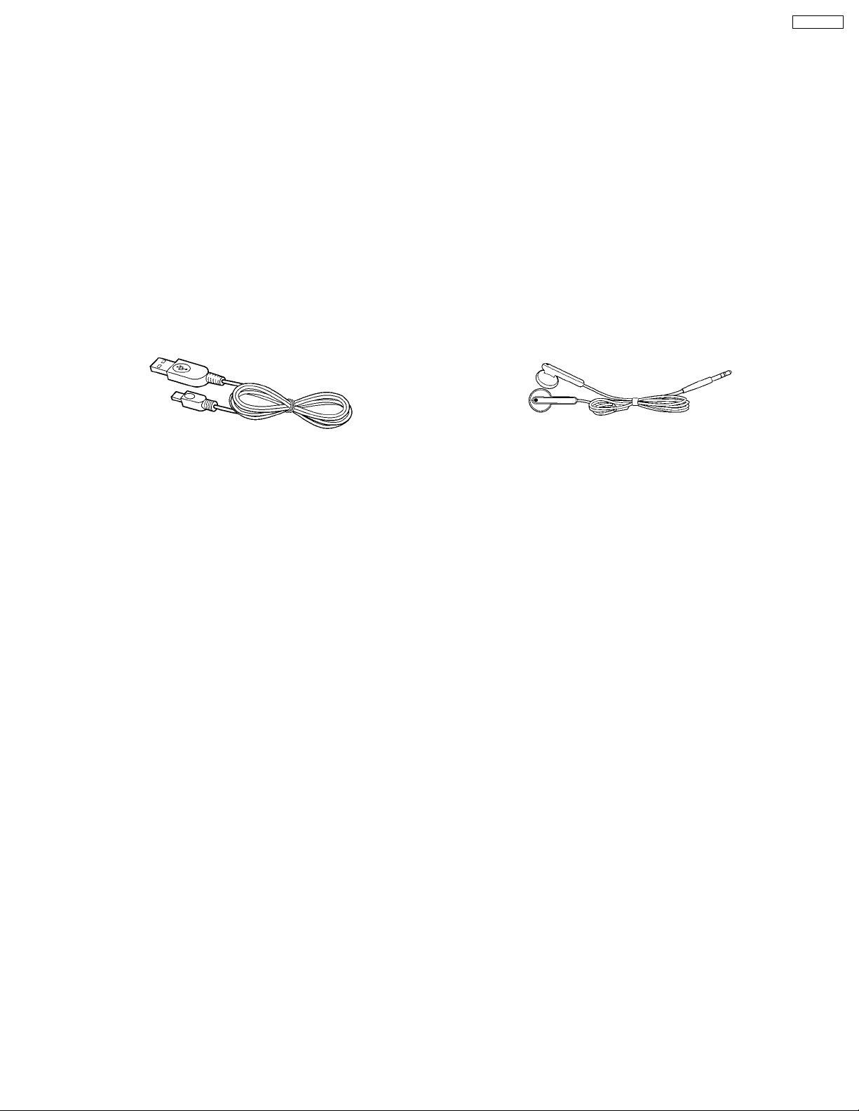
4 Accessories
SV-MP020P
· USB Cable (with Line-in)
(K1HA05AD0004) ............................................................. 1pc.
· Strap Stereo earphones
(L0BAB0000197).................................................................1pc.
3
SV-MP020P
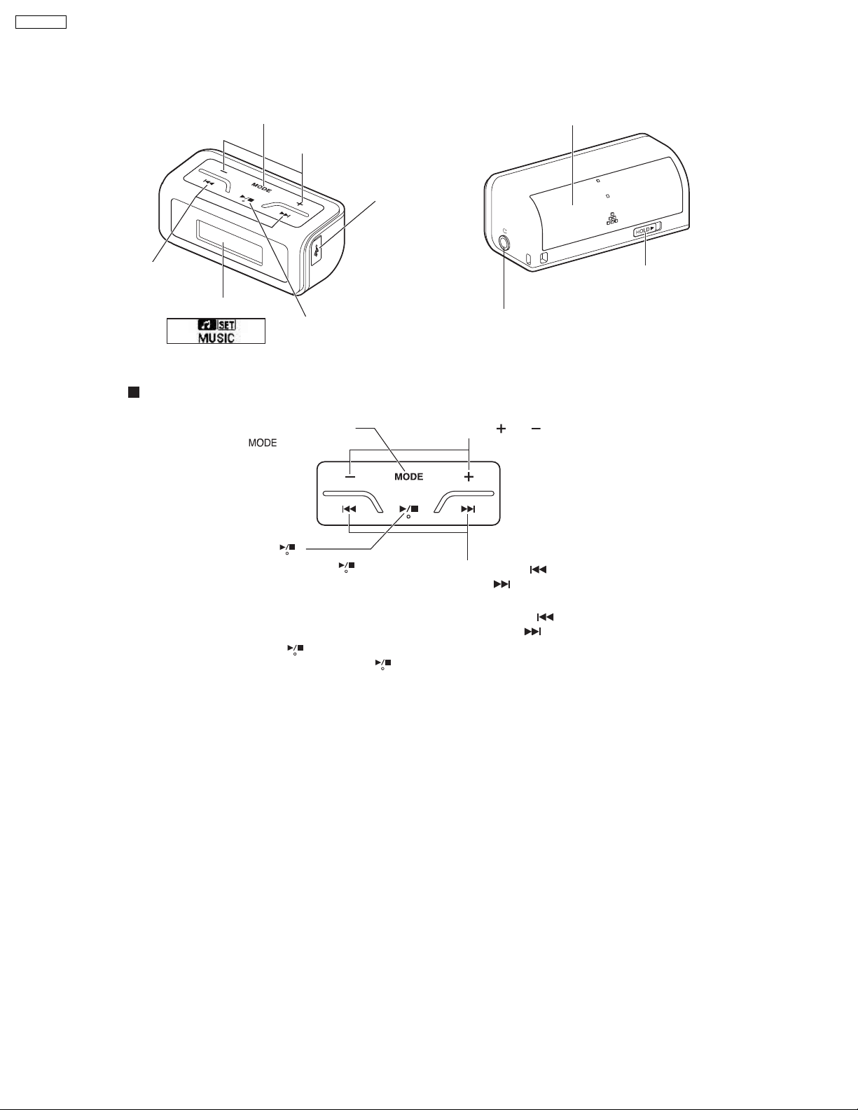
5 Location of Controls
MODE button
Skip/Search
button
Display
Basic playback operations
Display the main menu:
Press [
Volume button
USB port
Turn on, off /
Play/Stop button
]
Battery lid
HOLD switch
Earphones jack
Ø3.5mm (1/8") Stereo mini
Adjust the volume:
Press [
] or [ ] (0-25)
Turn ON: Press [ ]
Turn OFF: Press and hold [ ]
•
"Good bye" is displayed, and the unit's
power is turned off.
The power cannot be turned off while the
•
menu is displayed.
Play/Stop: Press [ ]
When you next press [
play resumes from where you
stopped it. (Resume)
],
Skip: Press [ ] (backward) or
] (forward)
[
Search: During play, press and
hold [
or [
] (backward)
] (forward)
4
SV-MP020P
6 Operation Checks and
Component Replacement
Procedures
1. This section describes procedures for checking the
operation of the major printed circuit boards and replacing
the main components.
2. For reassembly after operation checks or replacement,
reverse the respective procedures special ressembly
procedures are described only when required.
3. Select item from the following index when checks or
replacement are required.
Contents
1. Checking for the main P.C.B.
2. Checking for the memory P.C.B.
3. Checking for the LCD ass’y.
4. Checking for the prevent electrostatic discharge.
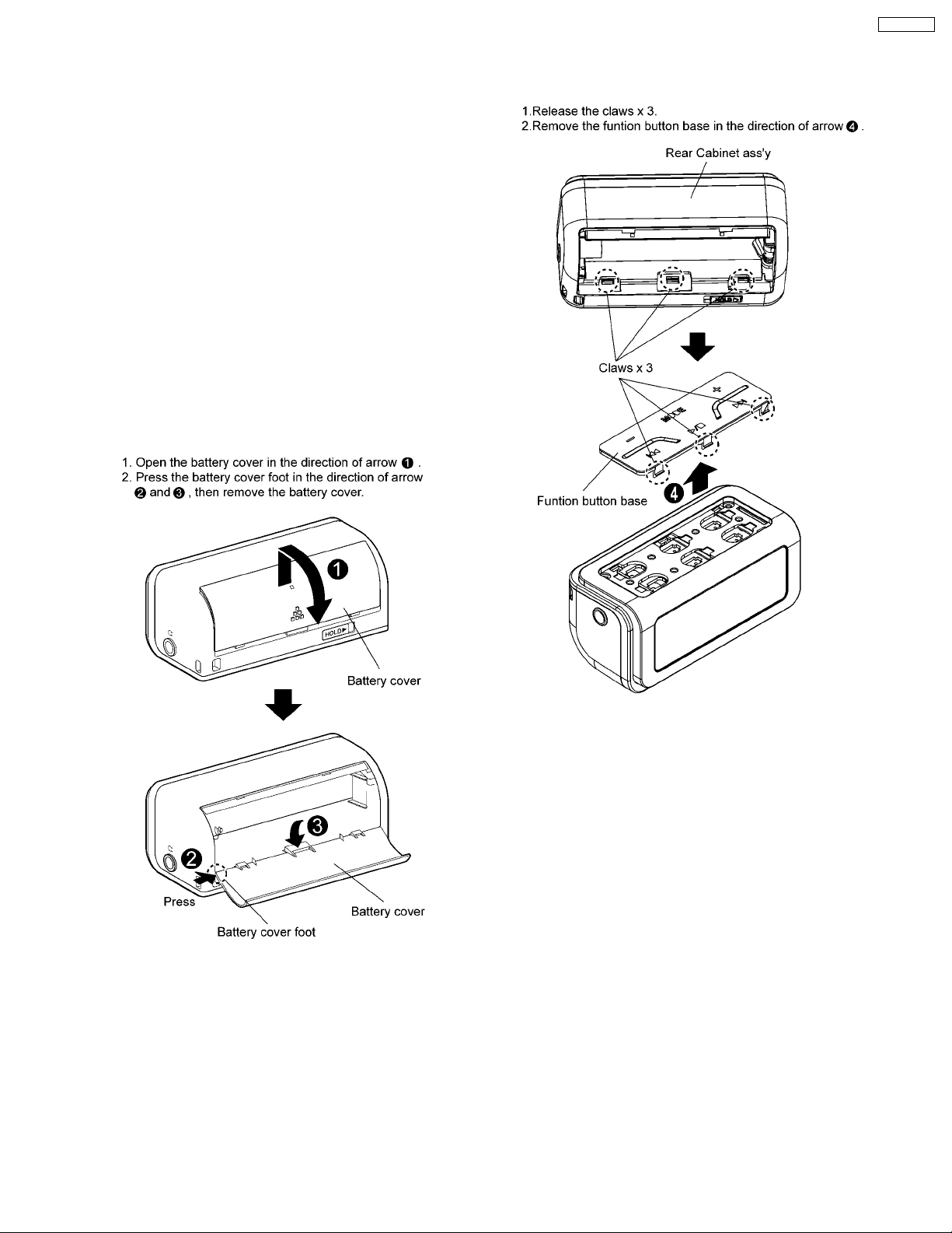
6.1. Removal of the battery cover
6.2. Removal of the funtion button
base
5
SV-MP020P
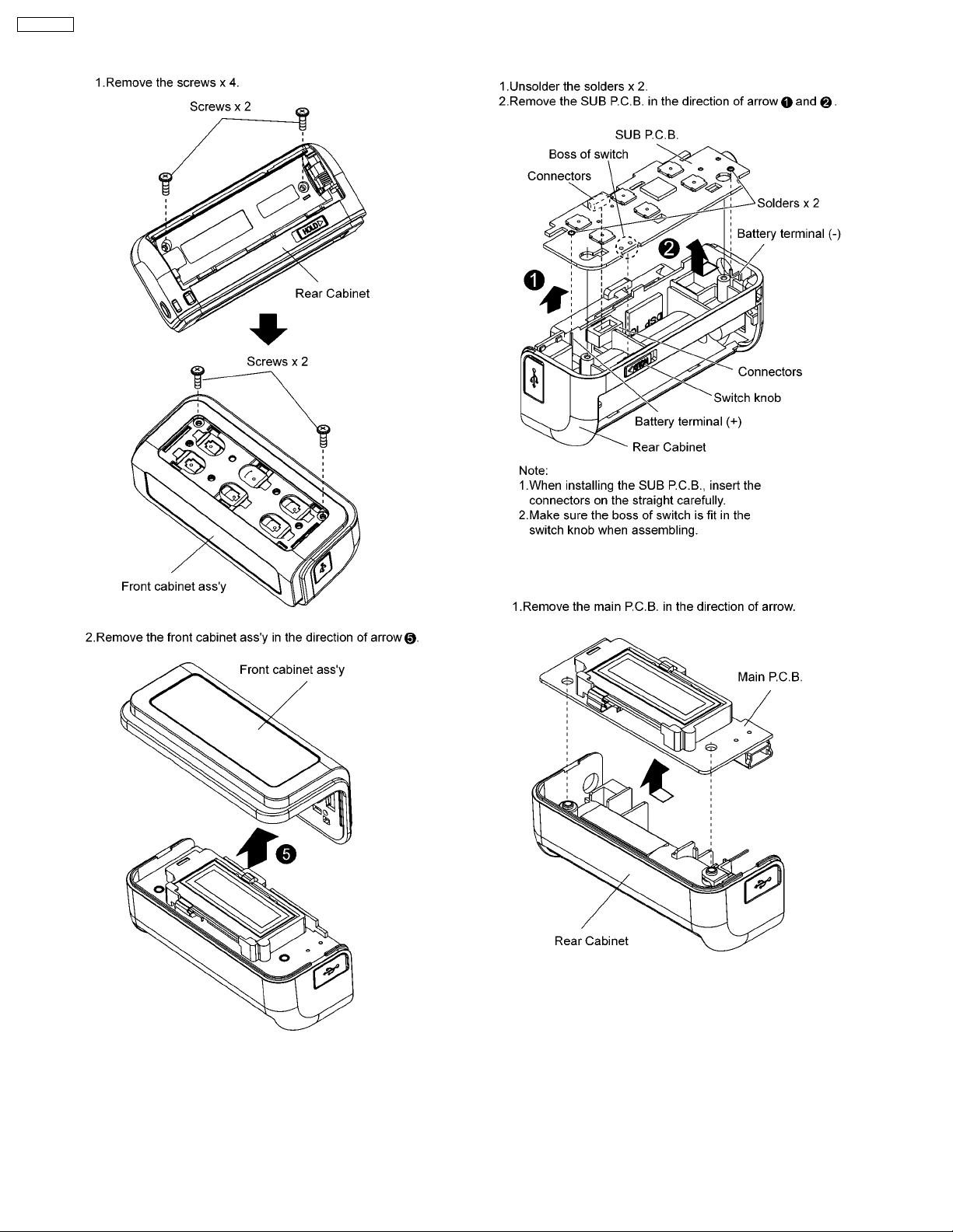
6.3. Removal of the front cabinet 6.4. Removal of the SUB P.C.B.
6.5. Removal of the main P.C.B.
6
SV-MP020P
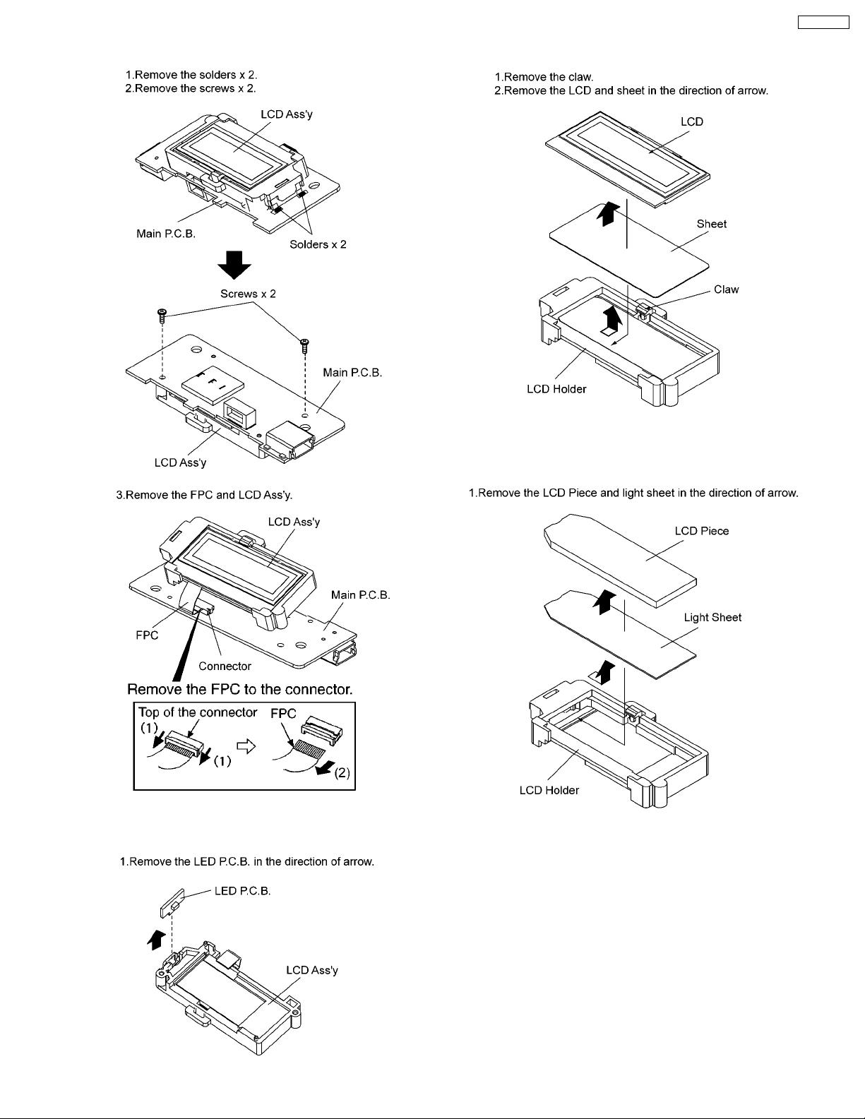
6.6. Removal of the LCD Ass’y
6.8. Removal of the LCD and sheet
6.9. Removal of the LCD piece and
LCD holder
6.7. Removal of the LED P.C.B.
7
SV-MP020P
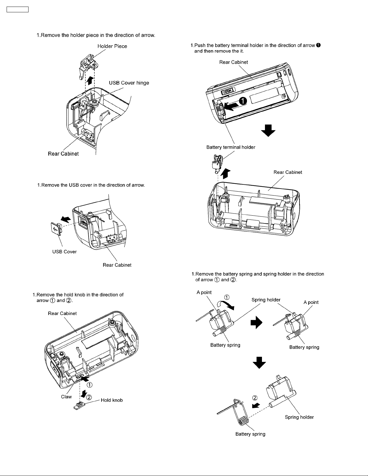
6.10. Removal of the holder piece
6.11. Removal of the USB cover
6.13. Removal of the battery
terminal holder
6.12. Removal of the hold knob
6.14. Removal of the battery spring
and spring holder
8
7 Service Position
SV-MP020P
9
 Loading...