

Page 1
Panasonic Service and Technology Company
SA-
Technical Guide
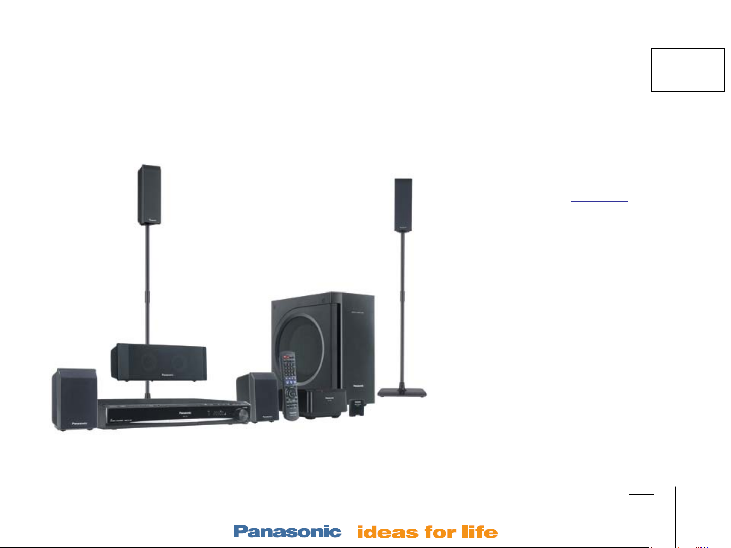
Home Theater Products Repair
60
For 2008-9 models:
PT7
SA-PT660
SA-PT760 / 954 / 956
SA-PT960
SH-FX65, 67, FX85
(wireless)
Contents
Hints / Layout / Reset 4
Wireless Section 8
Power On Sequence 14
5 Disc Mechanism (
CR-14)
o Operation 15
o Alignment 16
o Troubleshooting 21
o Laser replacement 25
Power Supply, 31
Herb Chin
Sample Model SC-PT760 Home Theater System
National Training
Protection Troubleshooting
(F61 or F76 Error Code) 34
No Audio (main unit) 39
Outline
Wireless
Mech
Pwr Supply
Protection
Audio
Models:
SA-PT660
SA-PT760
SA-PT960
SA-PT1060
SH-FX67, 85
Page 2

Panasonic Service and Technology Company
Produced by
Panasonic Services and Technology Company
National Training Department
Secaucus, NJ
Copyright © 2008 by Panasonic Services Company
All rights reserved. Unauthorized copying and distribution is a violation of law
Warning
This service information is designed for experienced repair technicians only and is not designed for use by
the general public. It does not contain warnings or cautions to advise non-technical individuals of potential
dangers in attempting to service a product. Products powered by electricity should be serviced or repaired
only by experienced professional technicians. Any attempt to service or repair the product or products dealt
with in this service information by anyone el se coul d result in seri o us injury or death.
Outline
Wireless
Mech
Pwr Supply
Protection
Audio
Models:
SA-PT660
SA-PT760
SA-PT960
SA-PT1060
SH-FX67, 85
Page 3
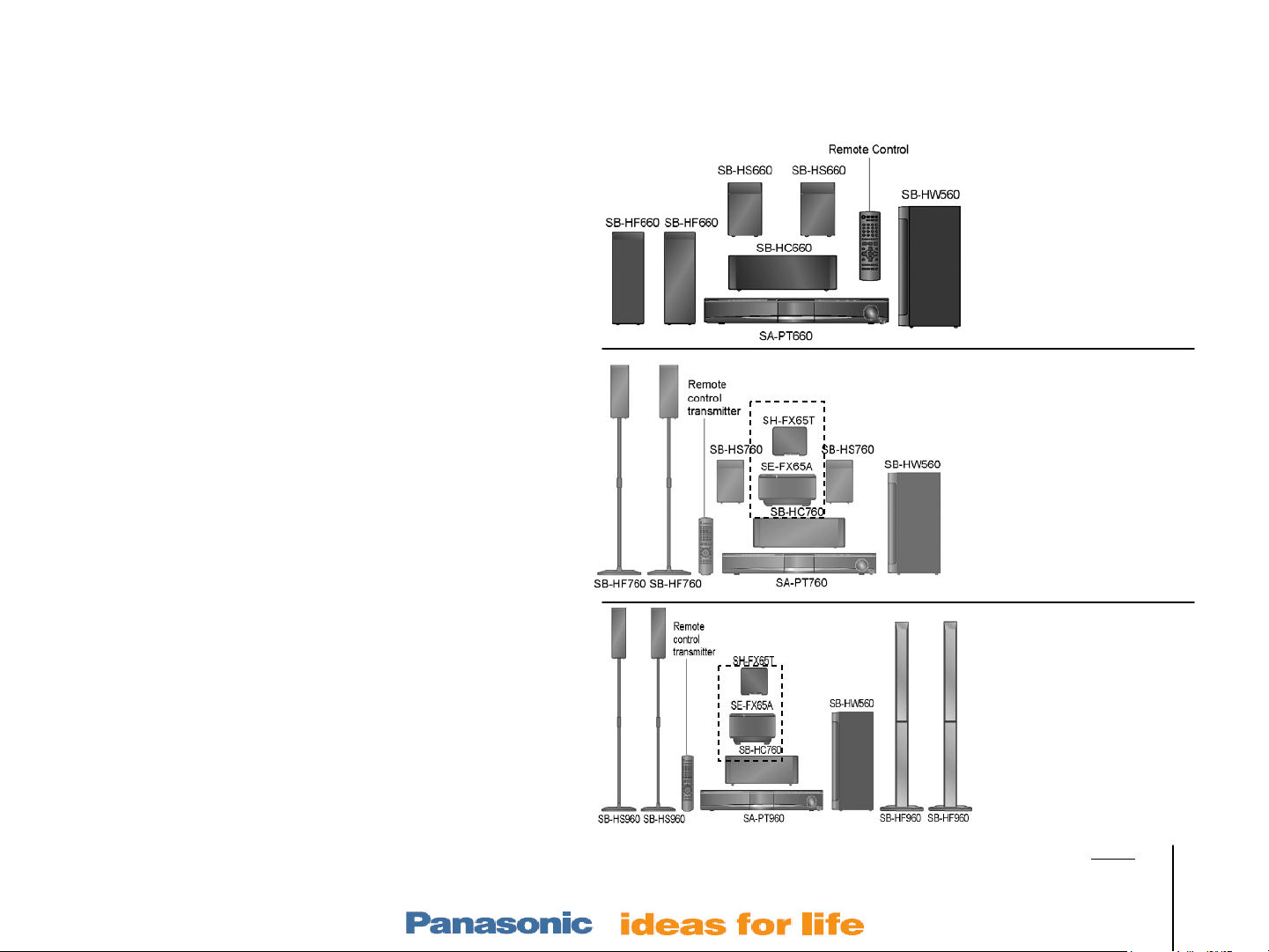
Table of Contents
Electronics –Layouts / Hints
Hints – p/n, New codes, Tests, Reset 4
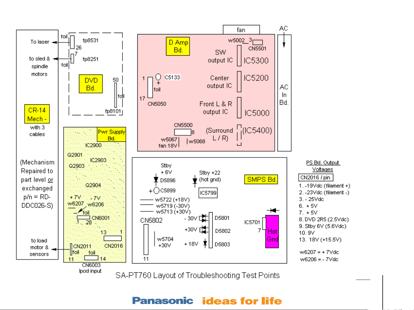
Layout w test points and PS voltages 5
Wireless
SH-FX65/66 Rear Receiver Setup 8
Wireless Troubleshooting Plan 9
Testing & Paring Trans & Rec 10
Transmitter / Receiver Repair Info 11
Power ON
Power On Sequence 14
Mechanism – stacked 5 Disc model CR-14
Operation 15
Alignment 16
Troubleshooting 21
Laser Replacement (removal & install) 25
Power Supply
PS Block with isolation strategy 31
Home Theater Products Repair
center SW
T
R
SW
center
SA-PT660
SA-PT760
PS Circuit with ref voltages 32
Protection
Protection Concept (F61 & F76 codes) 34
Protection Circuitry 35
Protection Repair Procedure 36
Audio
Concept 39
Speaker Output Waveform 40
Sample Problems & Repair Methods 41
Slide # 3
T
R
center
SW
SA-PT960
Outline
Wireless
Mech
Pwr Supply
Protection
Audio
Models:
SA-PT660
SA-PT760
SA-PT960
SA-PT1060
SH-FX67, 85
Page 4
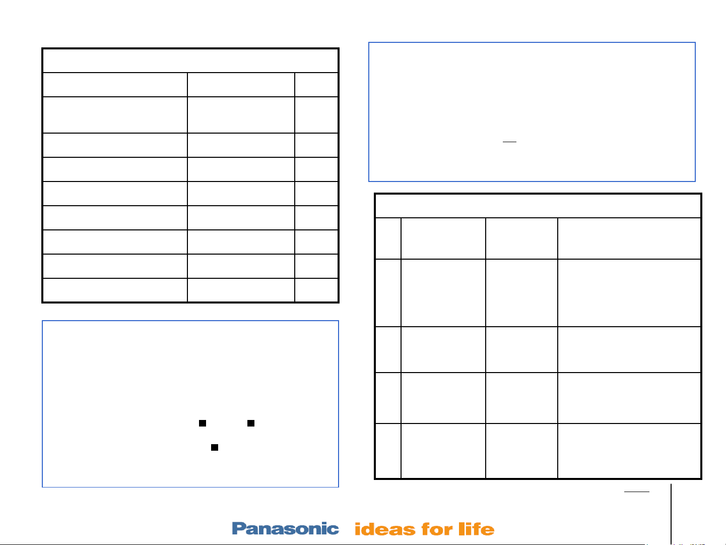
Hints – I Common P/N, II Missing error codes, III Unplugged cable symptoms, IV Reset
Remote SA-PT760,
PT960
Remote SA-PT660 N2QAyb 000 210
Fan L6FAJCCH 0007
Output ICs C1bA 00000 487
Transmit Card Repx 0644b
Receiver card Repx 0645b
CR-14 Mechanism RD-DDC026-S Exch
Traverse / Laser Assem RR-DDtx002-V
IV Reset after DVD Board replacement
1. After replacing the DVD board Play recovery disc
2. Reset –
Slide # 4
I Popular Part Numbers
Description P/N Note
N2QAyb 000 214
(p/n = RFKZD 03r005) containing firmware +
update. Select yes or no for update.
1. Select DVD mode & wait for “1 No Disc” display.
2. Press >10 (remote) and (panel). = Stop.
3. Until the display = “INIT”.
4. While still pressing STOP , also press the remote
OK button until the word “RESET” appears.
5. Power off the unit and unplug for 1 min.
II Error Codes not in the Service Manual:
Changer Error – appears when a button is pressed and the
mechanism is not responding. Go to the mechanism troubleshooting of
this book to determine if it is mechanical.
Sum Error – Incorrect communications with DVD board micro.
Transport is dead, DVD can not
cable or DVD bd.
be selected. Replace 50 pin ribbon
F897 – Play the recovery disc and reset the unit. (see IV at left)
III Troubleshooting by cable Removal
Cable
Removed
1 Large 50 pin
DVD cable
CN2001 off
2 2 rear mech
cables off
(fp8531,fp8251)
3 Main Bd.
CN2007 off
4 PS Bd /
mech
CN2011 off
Display Symptom
Hello, Aux
(last input),
Close,
“change
error”
Hello, Din.
None
Hello,
Change,
Open.
Fan on, No AM/FM mode,
No audio. Unit remains on.
Vol level # changes w knob
but no audio.
Fan on, Mech motor buzzes,
display skips DVD when
press Sel button, No audio.
CN2007 is only for the
display. No display. Unit
works OK otherwise.
Fan on, locked on last input
mode used but that audio
works fine with volume
control.
Outline
Wireless
Mech
Pwr Supply
Protection
Audio
Models:
SA-PT660
SA-PT760
SA-PT960
SA-PT1060
SH-FX67, 85
Page 5
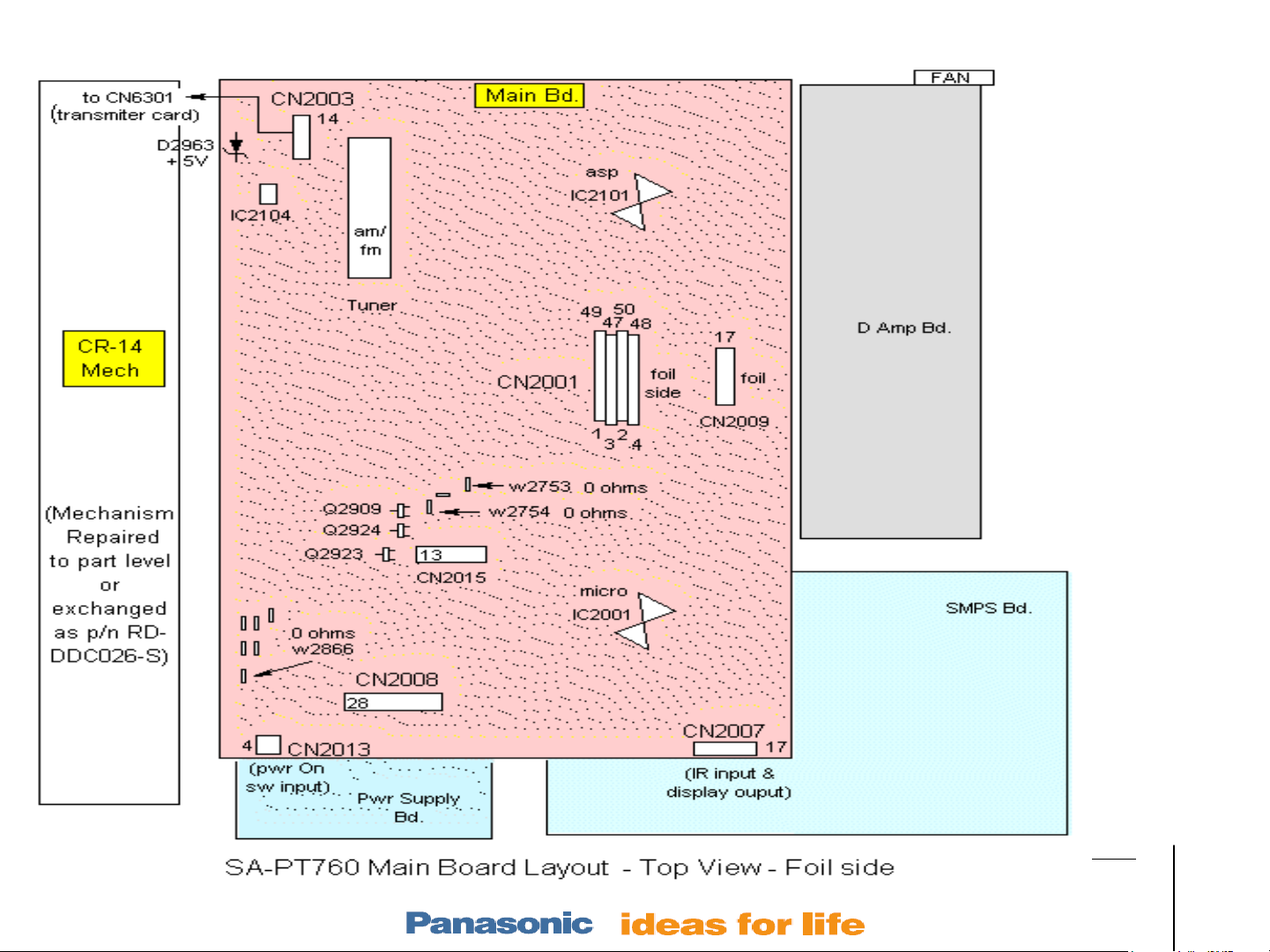
PT760 Layout 1 – Top Level
Slide # 5
Outline
Wireless
Mech
Pwr Supply
Protection
Audio
Models:
SA-PT660
SA-PT760
SA-PT960
SA-PT1060
SH-FX67, 85
Page 6
PT760 Layout – Bottom Level
Slide # 6
Outline
Wireless
Mech
Pwr Supply
Protection
Audio
Models:
SA-PT660
SA-PT760
SA-PT960
SA-PT1060
SH-FX67, 85
Page 7
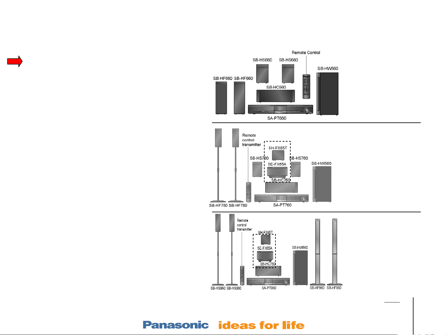
Table of Contents
Electronics –Layouts / Hints
Hints – p/n, New codes, Tests, Reset 4
Layout w test points and PS voltages 5
Wireless
SH-FX65/66 Rear Receiver Setup 8
Wireless Troubleshooting Plan 9
Testing & Paring Trans & Rec 10
Transmitter / Receiver Repair Info 11
Power ON
Power On Sequence 14
Mechanism – stacked 5 Disc model CR-14
Operation 15
Alignment 16
Troubleshooting 21
Laser Replacement (removal & install) 25
Power Supply
PS Block with isolation strategy 31
Home Theater Products Repair
center SW
T
R
SW
center
SA-PT660
SA-PT760
PS Circuit with ref voltages 32
Protection
Protection Concept (F61 & F76 codes) 34
Protection Circuitry 35
Protection Repair Procedure 36
Audio
Concept 39
Speaker Output Waveform 40
Sample Problems & Repair Methods 41
Slide # 7
T
R
center
SW
SA-PT960
Outline
Wireless
Mech
Pwr Supply
Protection
Audio
Models:
SA-PT660
SA-PT760
SA-PT960
SA-PT1060
SH-FX67, 85
Page 8
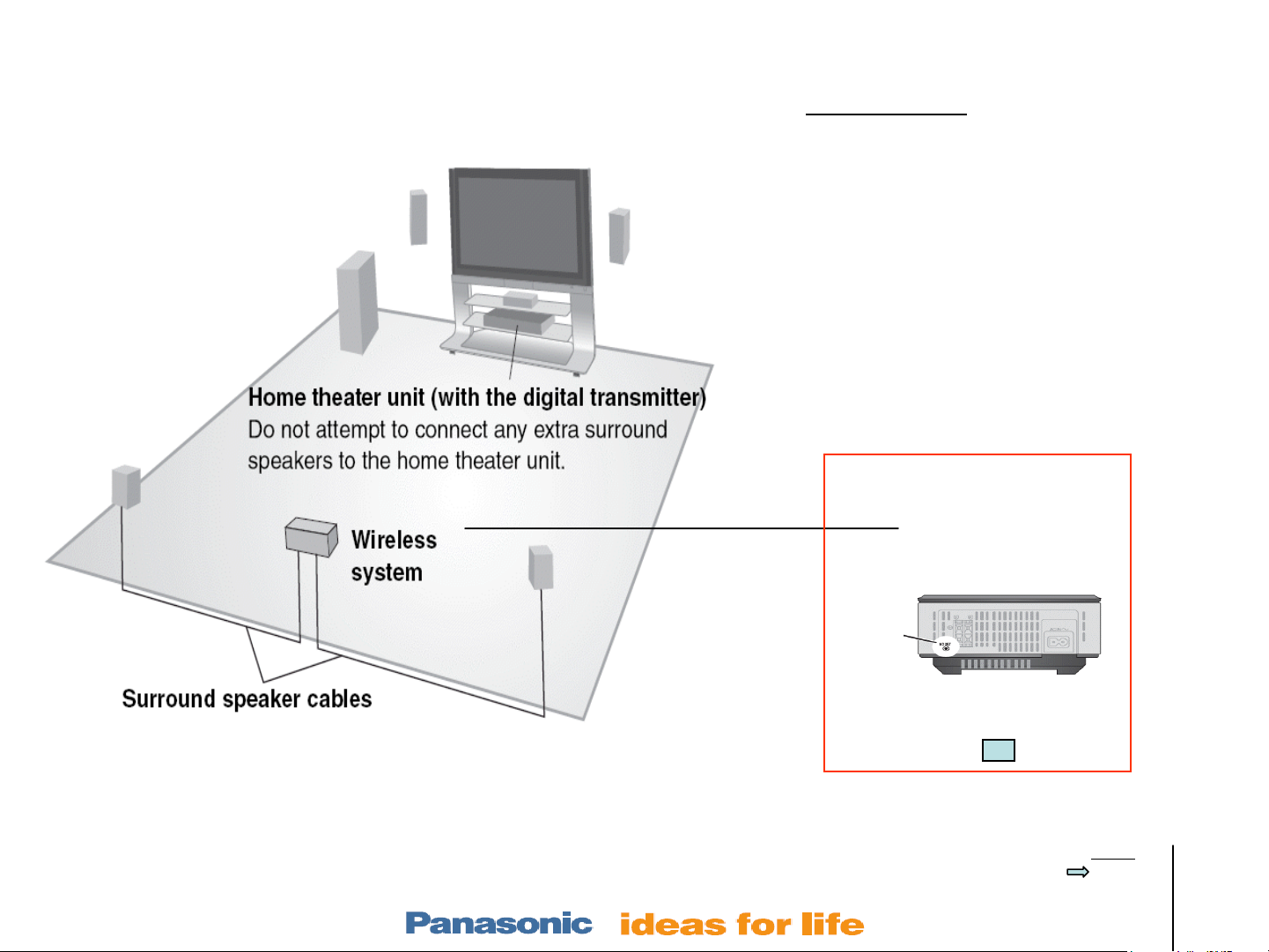
Home Theater Wireless Products
Panasonic Model
SA-PT660 – no wireless spks.
(optional FX67 or / & FX85)
SA-PT760 – wireless rear spks.
SA-PT960 – wireless rear spks + more pwr
Need a manual for the wireless
portions of the above units? Try a
model below.
SH-FX65 – takes spk wires.
SH-FX67 – takes spk plug.
Wireless rear receiver
Optional for the ‘PT660
SH-FX65/67
max range = 49’
Slide # 8
Transmitter card – REPX 0644b
Receiver card - REPX 0645b
ID set
button
(back)
Receiver
Transmitter card
Outline
Wireless
Mech
Pwr Supply
Protection
Audio
Models:
SA-PT660
SA-PT760
SA-PT960
SA-PT1060
SH-FX67, 85
Page 9

SA-PT760 Wireless Troubleshooting Plan
Wireless rear does not work – W1 or W2 display icons do blink at power on.
1. RF connection has not been made. Go to slide 6 to pair the transmitter and receiver.
Steps 1-6.
2. Go to slide 8 to troubleshoot the receiver. Make sure there is standby voltage input the
receiver and the pair button is working (pin 9 grounds when the button is pressed.
3. Go to slide 7 to check the transmitter card Sw +5V voltage at the main board (CN2003)
or at the card socket itself CN6301).
Wireless rear does not work – W1 or W2 display icons do NOT blink at power on.
1. The RF connection is OK. No audio is the problem. Replace the transmitter card if
hot (damaged when plugged in while the unit was powered on).
2. Go to slide 6 and follow steps 7 to turn on “S Music” mode (surround music). This
makes the rear surround speaker sound the same as main L & R.
Slide # 9
3. Input an audio source (play some music).
4. Disconnect the speakers and turn the volume control to max (level number 50 is
displayed).
5. Go to slide 8. Check for audio at the receiver card CN1100/pins 2 & 4.
6. If there was no audio present at CN1100 (receiver), Go to slide 7. Check for audio at
the transmitter socket CN6301/pins 10 & 12.
Outline
Wireless
Mech
Pwr Supply
Protection
Audio
Models:
SA-PT660
SA-PT760
SA-PT960
SA-PT1060
SH-FX67, 85
Page 10
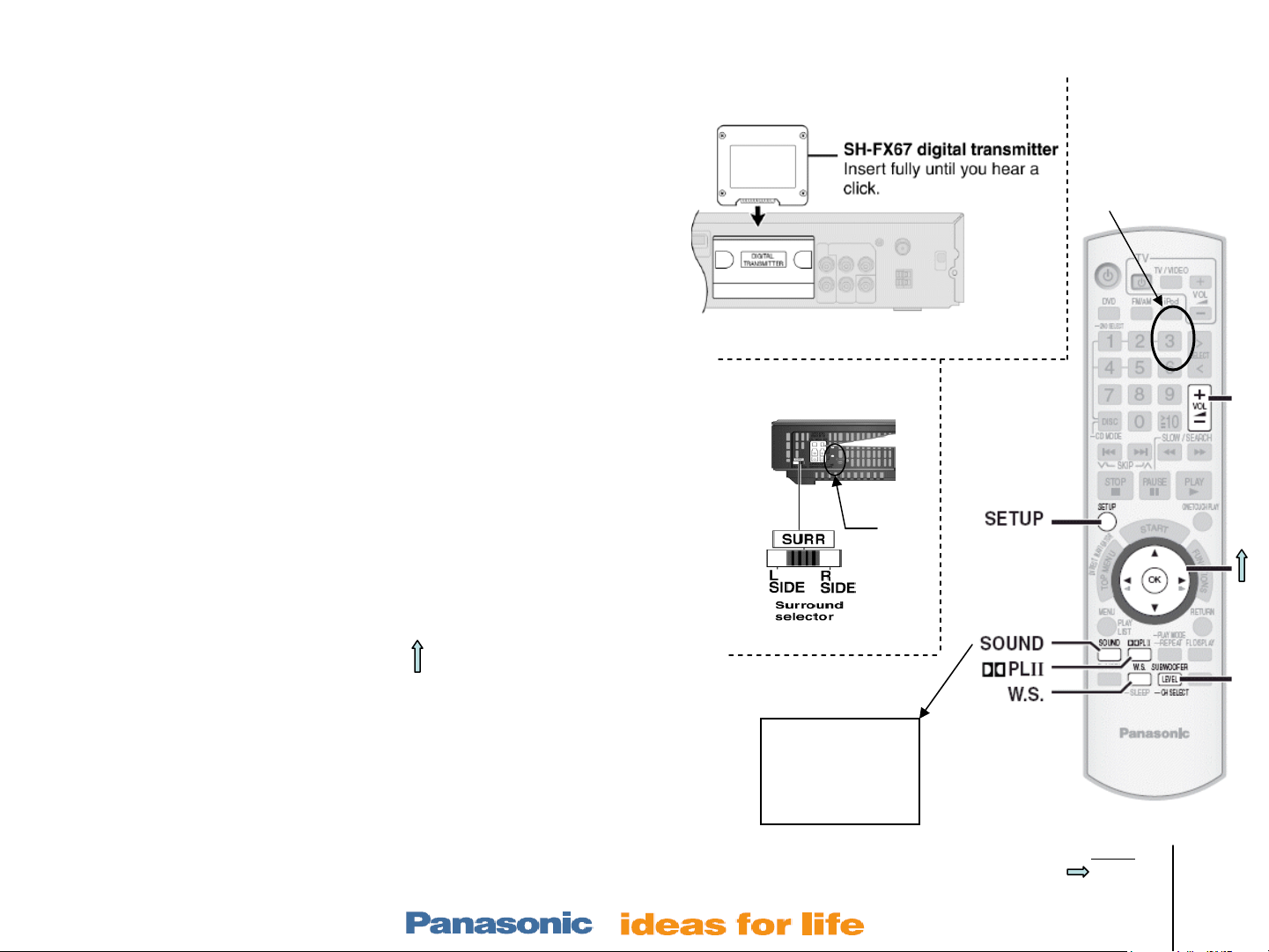
Wireless Information – RF Pairing / Matching T & R
RF Pairing
1. Proximity – Bring the wireless receiver to the transmitter.
2. Power ON – Plug the transmitter card in. Turn everything on
and press the selector button for DVD mode. (Do not plug
the card in with the unit on. A damaged card will get hot.)
3. Setup – While the W1 / W2 icon is blinking in the unit’s
display, hold down the front panel FF button and the
remote’s “3” Button.
4. Indicators – a) W1 / W2 will blink on the main unit’s display
if the transmitter card is inserted. b) “P” icon will be
displayed when the pairing process is started.
5. Mating – While the “P” is present, press the rear receiver
recessed “ID Set” button.
6. Indicator – The W1 / W2 will stop blinking proving an RF
match has been made.
2. Transmitter card
5. ID Set button
ID
Set
3. Press
panel FF &
3 buttons
On
7. Audio Test – Repeatedly press the remote’s SOUND button until the
panel displays “S.Music”. Then press the arrow button to turn ON “S.
Music”. The rear speakers will have the same music as the front L & R.
8. W1 / W2 still blinking? – Use the troubleshooting info in the next pages.
Slide # 10
7. Rear Audio Test
1. H. Bass
2. R.C. FCS
3. SRD Enh(ance)
4. S.Music
Outline
Wireless
Mech
Pwr Supply
Protection
Audio
Models:
SA-PT660
SA-PT760
SA-PT960
SA-PT1060
SH-FX67, 85
Page 11
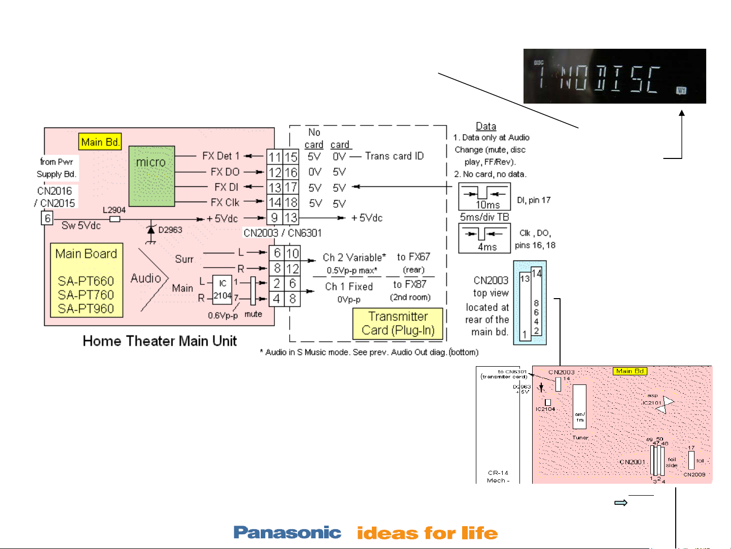
Wireless - Troubleshooting Information ½ - Transmitter part
Use this diagram to:
Prove that the T card is recognized (CN2003/pin 11).
Power is getting to the T card (CN2003/pin 9).
Audio is getting to the T card (CN2003/ pin 2-8).
When the T card is
inserted, the micro
blinks a W1 icon
Transmitter card – REPX 0644b
Receiver card - REPX 0645b
Notes:
1. Measure the voltages at the CN2003 main board with the Transmitter
card / Bd. plugged in.
2. Channel 2 audio is present with a surround sound DVD or if the S
Music is turned ON. See the previous slide, step 7 for access S Music.
nd
3. Channel 1 audio is only present when its 2
room accessory
transmitter card is plugged in. Otherwise channel 1 is muted.
4. Data is only present when the T card is in.
Slide # 11
Rear of Main Unit
Outline
Wireless
Mech
Pwr Supply
Protection
Audio
Models:
SA-PT660
SA-PT760
SA-PT960
SA-PT1060
SH-FX67, 85
Page 12
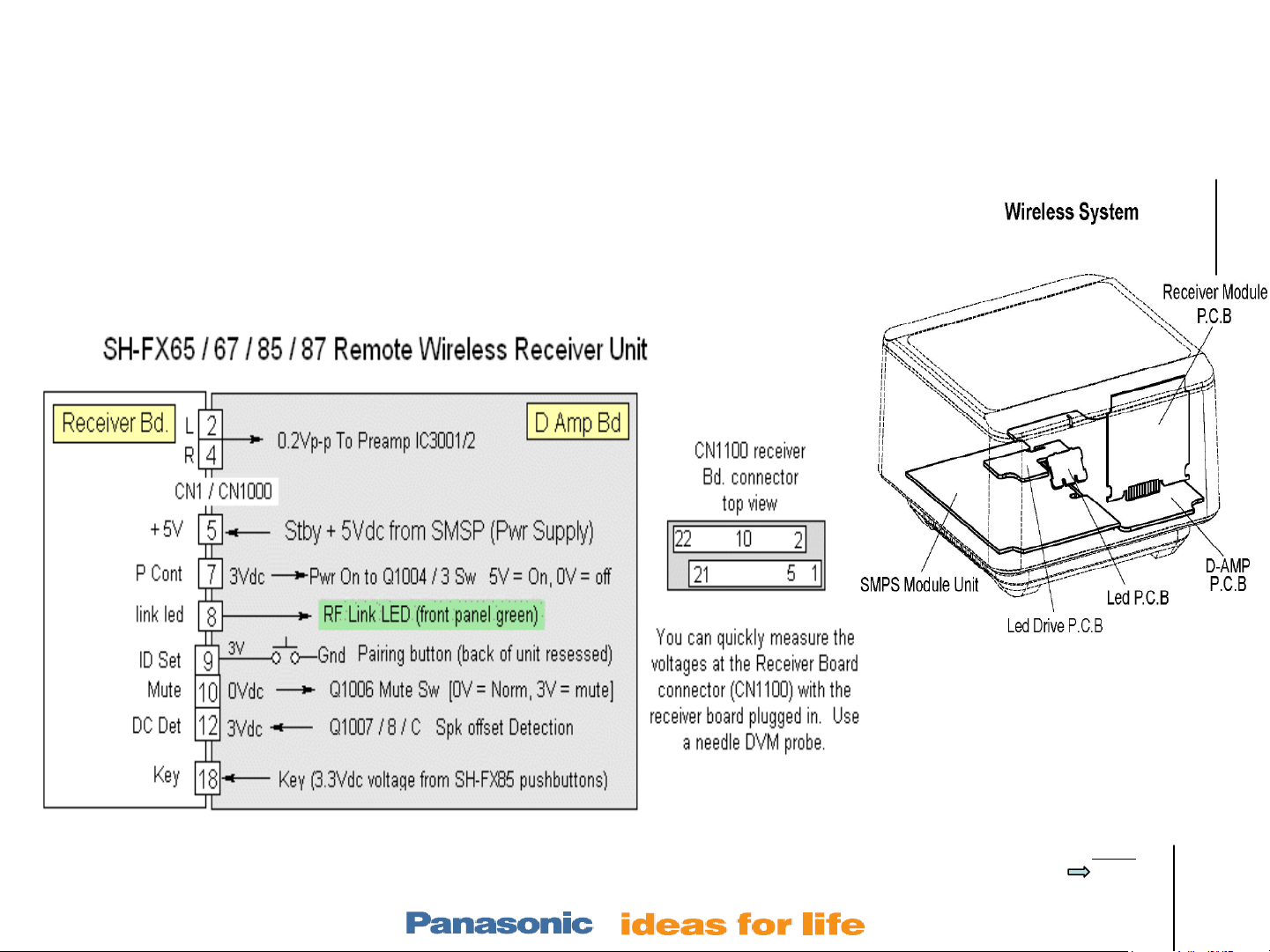
Wireless - Troubleshooting Information 2/2 – Receiver part
Use this diagram to:
Receiver card is getting power (CN1100/pin 5).
Receiver card is outputting Audio (CN1100/ pin 2).
Receiver card is not muting the audio (CN1100/ pin 10).
Transmitter card – REPX 0644b
Receiver card - REPX 0645b
SH-FX67
receiver / amp
Slide # 12
Outline
Wireless
Mech
Pwr Supply
Protection
Audio
Models:
SA-PT660
SA-PT760
SA-PT960
SA-PT1060
SH-FX67, 85
Page 13
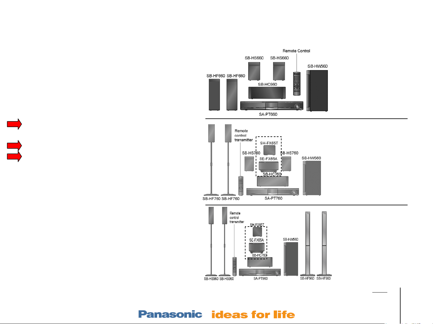
Table of Contents
Electronics –Layouts / Hints
Hints – p/n, New codes, Tests, Reset 4
Layout w test points and PS voltages 5
Wireless
SH-FX65/66 Rear Receiver Setup 8
Wireless Troubleshooting Plan 9
Testing & Paring Trans & Rec 10
Transmitter / Receiver Repair Info 11
Power ON
Power On Sequence 14
Mechanism – stacked 5 Disc model CR-14
Operation 15
Alignment 16
Troubleshooting 21
Laser Replacement (removal & install) 25
Power Supply
PS Block with isolation strategy 31
Home Theater Products Repair
center SW
T
R
SW
center
SA-PT660
SA-PT760
PS Circuit with ref voltages 32
Protection
Protection Concept (F61 & F76 codes) 34
Protection Circuitry 35
Protection Repair Procedure 36
Audio
Concept 39
Speaker Output Waveform 40
Sample Problems & Repair Methods 41
Slide # 13
T
R
center
SW
SA-PT960
Outline
Wireless
Mech
Pwr Supply
Protection
Audio
Models:
SA-PT660
SA-PT760
SA-PT960
SA-PT1060
SH-FX67, 85
Page 14

Unit Operation - Plug in, Power On Sequence
1. Plug In, Press Power On
Fan
2. Fan turns on - starts noisy (high speed)
3. Hello is displayed
4. Last Mode used is displayed
(DVD, Aux, D-in, Am, FM, or IPod)
DVD Mode
5. Micro checks “Top” & “Home” mech
switches to ID tray 1 (SW3 & Q3 = 0Vdc =
tray 1 loaded in the laser).
6. If tray 1 is not in the laser compartment
(default), the mech will load tray 1 in:
• Not tray 1 moves to stock (center) position. (Q1 UD
sensor = 0Vdc to stop rear traverse motor)
• Elevator moves laser assembly up to tray 1 level (SW 3
= 0Vdc at top level to stop the stock/elevator motor @
tray 1)
• Tray 1 is pulled into the laser assembly
Tray 1
laser
Trays
stocked
mech
SA-PT760
Top view
mech
Aux, D-in, Am, FM, or IPod Mode
5. Use the panel “Select” button to
change modes or the < or >
buttons to change stations.
6. Tray 1 status is displayed (disc
tracks or time or No disc)
Tray
release
7. With Tray 1 in the laser compartment, Disc
Detection occurs
laser on, focus searches. Disc spins if a disc is found.
8. Tray 1 status (contents if any) is displayed.
Slide # 14
• Mech clamps the disc
– Laser moves away from home,
Tray out
position
Outline
Wireless
Mech
Pwr Supply
Protection
Audio
Models:
SA-PT660
SA-PT760
SA-PT960
SA-PT1060
SH-FX67, 85
Page 15

5 Disc Mechanism - Operation
Default position = Tray 1 is loaded into the laser assembly at plug-in, power-on when the DVD
function is selected. The remaining 4 trays are in the middle “stock” area.
laser
Trays 2-5rear
Side View
Stock
location
Tray 5 selection
– (button 5 is pressed)
a) Press 5 button – Display = “Disc 5”
b) Laser unclamps and the tray returns to middle stock location (TRV motor).
c) Display = “Change”
d) Laser assembly lowers to tray 5 location (Stocker motor).
e) TRV motor pulls tray 5 into the laser assembly.
f) TRV motor clamps the disc if any.
g) TRV motor moves the sled away from home position to begin disc readout for play.
All Trays out – (Close / Open button is pressed)
a) Laser drops down (unclamps) and tray returns to middle stock location (TRV motor).
b) Stocker motor continues to turn to internally catch all 5 gears of the #328 “OC” gear. When the last gear is
caught, all the trays are moved to the end of the stock area almost out of the mechanism (for disc insertion)
Slide # 15
Outline
Wireless
Mech
Pwr Supply
Protection
Audio
Models:
SA-PT660
SA-PT760
SA-PT960
SA-PT1060
SH-FX67, 85
Page 16

5 Disc Mechanism - Concept & Transfer Alignment 1/4
Operational Concept:
There are 2 motors and 8 sensors in the CR-14 mech.
laser
Figure 1a – Default position
side view
Figure 1b – mech components
Mech
p/n = RD-ddc 026-S
Stock
area
rear
I. The traverse motor moves:
Trays 2-5rear
• Laser back & forth
• Clamps disc
• Pulls trays into the laser assembly
traverse
motor
Tray 1
laser
II. The stocker motor moves
• Tray(s) between the middle stocker
area and out of the assembly
(for disc insertion)
• Traverse / laser platform up/dwn,
III. Trays moved from the stock area must be
Stock
motor
Top
view
transferred to the laser area.
1) Tray transfer is made after the traverse assembly
elevators to the desired tray level. The following
occurs in the rear traverse assembly:
2) The traverse motor uses arms to pull the tray into
gear #331. Pictures in the fourth slide 4/4.
3) SW4 opens (fp 8251) to tell the micro the tray is in.
4) The traverse motor continues to turn, bringing the tray
in, then clamps the disc
5) SW5 opens (fp 8251) at clamp end and sled moves
away from home.
Traverse
assembly p/n =
RD-DDtx002-V
6) The sled moves the laser to the approx TOC disc
area & stops. The laser comes on, lens focus
searches and if a disc is found, spins it.
7) SW4 and SW5 are both inside the Traverse
assembly.
Slide # 16
Outline
Wireless
Mech
Pwr Supply
Protection
Audio
Models:
SA-PT660
SA-PT760
SA-PT960
SA-PT1060
SH-FX67, 85
Page 17

5 Disc Mechanism - Assembly Transfer Alignment – Trays Out 2/4
Preparing the Traverse unit
for docking:
1. Trays Out (laser down)
2. Rotate the black gears so
the white slider and laser
are forward, as shown.
Next page is a close up
picture.
Rear
Slide # 17
Figure 2
Outline
Wireless
Mech
Pwr Supply
Protection
Audio
Models:
SA-PT660
SA-PT760
SA-PT960
SA-PT1060
SH-FX67, 85
Page 18

5 Disc Mechanism Assembly Transfer Alignment – Trays Out 3/4
#331 gear
Preparing the Traverse unit for docking:
3. Slide the top #336 sub slide plate inside the
cutout to the left or as far as it will go without
force (pictured down).
4. This permits the other end of the #336 slide
plate to engage gear #331.
5. Rotate the #331 gear (cw) so the plastic arm
of the sub plate points past the triangle cutout, all
the way left as shown. This is the elev ator position.
6. The rear Traverse portion of the mech is ready
for docking with the front tray assembly.
7. Optional - At the middle tray area (fig 4), you may
manually rotate the stocking motor gear so the black gear
hole lines up here. It will pwr to this position anyway.
8. Plug in the mech’s 3 ribbon cables and test
.
rear
Slide # 18
cutout
left
front
Figure 3
Figure 4
Outline
Wireless
Mech
Pwr Supply
Protection
Audio
Models:
SA-PT660
SA-PT760
SA-PT960
SA-PT1060
SH-FX67, 85
Page 19

5 Disc Mechanism Assembly Transfer Alignment – Tray In 4/4
rear
Laser
area
Lever
#333
Gear #331
Stock
area
Fig 5 – Traverse assembly elevatored
up to tray level. Note position of #333
tray load lever for elevator operation.
Operational Concept Conclusion
III. Trays moved from the middle stock area
must be transferred to the laser area.
• Tray transfer is made after the traverse
assembly elevators to the desired tray level.
• The traverse motor uses arms to pull the tray
into gear #331. Details in slide 4/4, above.
• SW4 opens (fp 8251) to tell the micro the tray is
in.
Fig 6 – Traverse
motor moves #333
lever to pull tray 1 in.
Fig 7 - #333 lever
slips under tray 1.
Fig 8 - #333 lever pulls tray
1 into gear #331 on the
other side (not shown).
Gear #331 grabs the tray
teeth and pulls the tray into
the laser assembly.
Slide # 19
Outline
Wireless
Mech
Pwr Supply
Protection
Audio
Models:
SA-PT660
SA-PT760
SA-PT960
SA-PT1060
SH-FX67, 85
Page 20

Table of Contents
Electronics –Layouts / Hints
Hints – p/n, New codes, Tests, Reset 4
Layout w test points and PS voltages 5
Wireless
SH-FX65/66 Rear Receiver Setup 8
Wireless Troubleshooting Plan 9
Testing & Paring Trans & Rec 10
Transmitter / Receiver Repair Info 11
Power ON
Power On Sequence 14
Mechanism – stacked 5 Disc model CR-14
Operation 15
Alignment 16
Troubleshooting 21
Laser Replacement (removal & install) 25
Power Supply
PS Block with isolation strategy 31
Home Theater Products Repair
center SW
T
R
SW
center
SA-PT660
SA-PT760
PS Circuit with ref voltages 32
Protection
Protection Concept (F61 & F76 codes) 34
Protection Circuitry 35
Protection Repair Procedure 36
Audio
Concept 39
Speaker Output Waveform 40
Sample Problems & Repair Methods 41
Slide # 20
T
R
center
SW
SA-PT960
Outline
Wireless
Mech
Pwr Supply
Protection
Audio
Models:
SA-PT660
SA-PT760
SA-PT960
SA-PT1060
SH-FX67, 85
Page 21

Mechanism Access for Troubleshooting
Access - Cover removal
to view the mechanism
1. Left fig 9 - Push
down on the 2
plastic catches and
slide the top plastic
cover ¼” rearwards
to unlock.
2. Lift up the top plastic
cover about ¼” for
clearance and slide
out toward the front
to unhook the 2 tray
stop arms.
¼”
Slide # 21
3. Right fig 10 –
up
¼”
Remove the spindle
magnet plate by
pulling in on the 2
out
plastic catches, then
lift the plate up and
out.
Outline
Fig 9 – cover removal Fig 10 – spindle magnet plate
Wireless
Mech
Pwr Supply
Protection
Audio
Models:
SA-PT660
SA-PT760
SA-PT960
SA-PT1060
SH-FX67, 85
Page 22

Mech Troubleshooting. Is it the Mech or the Circuitry?
Troubleshooting concept: The fastest way to find out if the circuitry is causing the mech problem is to
check the sensors. When they turn on, they ground out the micro input lines, proving each sensor is OK.
Default
tray 1
position
Fig
11
rear
Fig
12
Isolation
Procedure:
1a. Note the
position of the
tray in the
jammed
mechanism
(pictured left).
1b. Unplug the
ribbon cable
from socket
CN2011.
2. Measure the
voltage at each
of the CN2011
socket pins.
The voltages
should be
identical to the
ones listed on
the next page.
Fig
13
Default = Tray 1 loaded
Slide # 22
(shown is tray 3 loaded)
Defect - All or some trays OutDefect -Trays 2-5 loaded
Outline
Wireless
Mech
Pwr Supply
Protection
Audio
Models:
SA-PT660
SA-PT760
SA-PT960
SA-PT1060
SH-FX67, 85
Page 23

Slide # 23
Mech Troubleshooting. Is it the Mech or the Circuitry?
When the mechanism does not work correctly, is the problem mechanical? Is it
a sensor under the mech? Is it on the main board by the microprocessor?
Isolation Procedure:
1. Note which tray is in the laser assembly. Unplug the ribbon cable at CN2011.
2. Compare the dc voltages at the 11 pin connector (without the cable inserted) to the
“No cable” column voltages shown below. If any are different, the main board is at fault.
Check the pull up resistors and check the main board for cracks.
3. Note the position of the trays in the mechanism. Reconnect CN2011.
4. Compare the dc voltages at the same CN2011 connector to the corresponding
column in the chart below (cable inserted). Pictures are on the previous page.
If any of the voltages do not agree with the chart below, the corresponding sensor (Q1-5, Sw3,4) is
bad. If the voltages all agree, the mechanical assembly is defective or out of alignment. Replace
the assembly, or do the prev. transfer alignment.
CN2011 Connector Voltage
CN2011/
pin
1 8.2V 7.5V 7.5Vdc 7.5Vdc Motor driver Vcc
2 gnd No change
3 5Vdc 5Vdc 5Vdc 5Vdc Q4 Mode sensor Elevator dwn
4 gnd
5 5Vdc 0Vdc 5Vdc 0Vdc SW3 Top sw
6 5Vdc 0Vdc 0Vdc 0Vdc Q1 UD (lever
7 0Vdc 0Vdc 0Vdc 0Vdc Motor fwd
8 0Vdc 0Vdc 0Vdc 0Vdc Motor rev
9 5Vdc 0Vdc 0Vdc 0Vdc Q2 close (gear
10 5Vdc 0Vdc 0Vdc 5Vdc Q3 home (gear
11 5Vdc 0Vdc 0Vdc 0Vdc Q5 open (lever
No CN2011
cable
Tray
1 in
Trays
2-5 in
All trays
out
CN2011/pin
corresponds to:
sensor)
sens)
sens)
sens)
Changes
during
Trays
stocked
Tray moves
back / forth
H at tray out
Outline
Wireless
Mech
Pwr Supply
Protection
Audio
Models:
SA-PT660
SA-PT760
SA-PT960
SA-PT1060
SH-FX67, 85
Page 24

Table of Contents
Electronics –Layouts / Hints
Hints – p/n, New codes, Tests, Reset 4
Layout w test points and PS voltages 5
Wireless
SH-FX65/66 Rear Receiver Setup 8
Wireless Troubleshooting Plan 9
Testing & Paring Trans & Rec 10
Transmitter / Receiver Repair Info 11
Power ON
Power On Sequence 14
Mechanism – stacked 5 Disc model CR-14
Operation 15
Alignment 16
Troubleshooting 21
Laser Replacement (removal & install) 25
Power Supply
PS Block with isolation strategy 31
Home Theater Products Repair
center SW
T
R
SW
center
SA-PT660
SA-PT760
PS Circuit with ref voltages 32
Protection
Protection Concept (F61 & F76 codes) 34
Protection Circuitry 35
Protection Repair Procedure 36
Audio
Concept 39
Speaker Output Waveform 40
Sample Problems & Repair Methods 41
Slide # 24
T
R
center
SW
SA-PT960
Outline
Wireless
Mech
Pwr Supply
Protection
Audio
Models:
SA-PT660
SA-PT760
SA-PT960
SA-PT1060
SH-FX67, 85
Page 25

5 Disc Mechanism Laser Replacement 1/5 – Removed from any play position
If the mechanism is replaced, The TRV / laser assembly is transplanted to the new mechanism.
Mech p/n = RD-DDC026-S
Traverse/Laser p/n = RD-DDtx002-V
Setup –
Move Mech to PLAY position:
A. Power the unit on, select
DVD and let the micro
back
automatically move the
mechanism to load tray 1,
play position
position is shown at left for
understanding only *).
(the default PLAY
B. Unplug the 3 cables and
Remove the mechanism.
Mech p/n = RD-DDC026-S
Traverse/Laser p/n = RD-DDtx002-V
Fig 14
Slide # 25
front
Panasonic CR-14
Mechanism -
Default Position
(no discs)
C. Turn the mech over.
Go to the next page.
* Verification is from the front panel tray
compartment. Trays 2-5 are seen below
but tray 1 is recessed (loaded).
Tray 1 inside
Trays 2-5
Front view
Outline
Wireless
Mech
Pwr Supply
Protection
Audio
Models:
SA-PT660
SA-PT760
SA-PT960
SA-PT1060
SH-FX67, 85
Page 26

5 Disc Mechanism Laser Replacement 2/5 – Removed from play position
front
# 336
# 335
back
D. Removing the Laser assembly
from the bottom in play position:
1. Locate the bottom of #335 TRV
slide plate and move the catch
up as shown.
2. Slide #336 sub slide plate to the
right as shown until the grooves
in the slot are revealed
(permitting the traverse
assembly to lift out).
3.
Go to the next page.
Fig 15
Slide # 26
Outline
Wireless
Mech
Pwr Supply
Protection
Audio
Models:
SA-PT660
SA-PT760
SA-PT960
SA-PT1060
SH-FX67, 85
Page 27

5 Disc Mechanism Laser Replacement 3/5 – Removed from play position
front
Removing the Laser assembly:
3. Lift up the TRV assembly in
the direction of the two
arrows shown.
Go to the next page.
Fig
16
Slide # 27
back
Outline
Wireless
Mech
Pwr Supply
Protection
Audio
Models:
SA-PT660
SA-PT760
SA-PT960
SA-PT1060
SH-FX67, 85
Page 28

5 Disc Mechanism Laser Replacement 4/5 – Installation
B A
Reinstalling the Laser
assembly:
4. Before dropping the laser
assembly into the TRV
assembly observe the two
areas (A & B) outlined.
5. During the insertion, mate
the pin of the laser slider
(A) to the mechanism’s
corresponding groove (B).
Slide # 28
Go to the next page.
Fig
17
Outline
Wireless
Mech
Pwr Supply
Protection
Audio
Models:
SA-PT660
SA-PT760
SA-PT960
SA-PT1060
SH-FX67, 85
Page 29
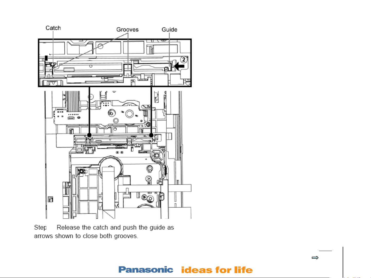
5 Disc Mechanism Laser Replacement 5/5 – Installation
Reinstalling the Laser assembly:
6. Drop the laser assembly in.
7. Slide the lever to the left as
shown in arrow 2.
8. Make sure the catch is back
down.
9. Finished. Turn the mechanism
over and connect the mech’s 3
ribbon cables to the remainder
of the unit.
Slide # 29
Fig 18
4
Outline
Wireless
Mech
Pwr Supply
Protection
Audio
Models:
SA-PT660
SA-PT760
SA-PT960
SA-PT1060
SH-FX67, 85
Page 30

Table of Contents
Electronics –Layouts / Hints
Hints – p/n, New codes, Tests, Reset 4
Layout w test points and PS voltages 5
Wireless
SH-FX65/66 Rear Receiver Setup 8
Wireless Troubleshooting Plan 9
Testing & Paring Trans & Rec 10
Transmitter / Receiver Repair Info 11
Power ON
Power On Sequence 14
Mechanism – stacked 5 Disc model CR-14
General Operation 15
Concept & Alignment 16
Failure? Mech or circuitry? Access 21
Laser Replacement (removal & install) 25
Power Supply
PS Block with isolation strategy 31
Home Theater Products Repair
center SW
T
R
SW
center
SA-PT660
SA-PT760
PS Circuit with ref voltages 32
Protection
Protection Concept (F61 & F76 codes) 34
Protection Circuitry 35
Protection Repair Procedure 36
Audio
Concept 39
Speaker Output Waveform 40
Sample Problems & Repair Methods 41
Slide # 30
T
R
center
SW
SA-PT960
Outline
Wireless
Mech
Pwr Supply
Protection
Audio
Models:
SA-PT660
SA-PT760
SA-PT960
SA-PT1060
SH-FX67, 85
Page 31

Dividing a PS problem to the
output or regulation stage
with 2 voltages.
Measure voltages. Look up voltages
on chart below for the defect area.
1
2
Power Supply Block for Stby, Pwr On, Isolation.
1. Output volt
@ w5713
2. FdBk volt
at w5711
Defect area
30Vdc 1.5Vdc Normal Operation
Lower than 30V Higher than 1.5V Reg circuit (IC5801, Q5802)
Lower than 30V Lower than 1.5V Output Stage (IC5701,
T5701, D5702)
Higher than 30V Higher than 1.5V Output Stage (IC5701,
T5701, D5702)
Higher than 30V Lower than 1.5V Reg circuit (IC5801, Q5802)
Slide # 31
Plug In, Power ON Sequence
1. Press Power ON
2. Fan turns on - Starts Noisy
3. Hello is displayed
4. Last Mode used is displayed.
Outline
Wireless
Mech
Pwr Supply
Protection
Audio
Models:
SA-PT660
SA-PT760
SA-PT960
SA-PT1060
SH-FX67, 85
Page 32

Power Supply Circuit
Slide # 32
Outline
Wireless
Mech
Pwr Supply
Protection
Audio
Models:
SA-PT660
SA-PT760
SA-PT960
SA-PT1060
SH-FX67, 85
Page 33

Table of Contents
Electronics –Layouts / Hints
Hints – p/n, New codes, Tests, Reset 4
Layout w test points and PS voltages 5
Wireless
SH-FX65/66 Rear Receiver Setup 8
Wireless Troubleshooting Plan 9
Testing & Paring Trans & Rec 10
Transmitter / Receiver Repair Info 11
Power ON
Power On Sequence 14
Mechanism – stacked 5 Disc model CR-14
Operation 15
Alignment 16
Troubleshooting 21
Laser Replacement (removal & install) 25
Power Supply
PS Block with isolation strategy 31
Home Theater Products Repair
center SW
T
R
SW
center
SA-PT660
SA-PT760
PS Circuit with ref voltages 32
Protection
Protection Concept (F61 & F76 codes) 34
Protection Circuitry 35
Protection Repair Procedure 36
Audio
Concept 39
Speaker Output Waveform 40
Sample Problems & Repair Methods 41
Slide # 33
T
R
center
SW
SA-PT960
Outline
Wireless
Mech
Pwr Supply
Protection
Audio
Models:
SA-PT660
SA-PT760
SA-PT960
SA-PT1060
SH-FX67, 85
Page 34

PT760 Protection Troubleshooting Concept
Slide # 34
Outline
Wireless
Mech
Pwr Supply
Protection
Audio
Models:
SA-PT660
SA-PT760
SA-PT960
SA-PT1060
SH-FX67, 85
Page 35

PT760 Protection Circuit
Slide # 35
Outline
Wireless
Mech
Pwr Supply
Protection
Audio
Models:
SA-PT660
SA-PT760
SA-PT960
SA-PT1060
SH-FX67, 85
Page 36

F61 / F76 error code Repair procedure (1/2)
Use the protection diagrams for strategy information (p32-33) and the layout diagram (p25-26) to
locate test points. The main strategy below is to first isolate the problem to one of 5 boards.
Board Isolation:
F61 Error Code
1. Even if the fan blades were spinning, replace the fan if the 3 pin CN5501 fan connector
voltages are 7vdc, 0V, and 0.6Vdc (normal = 7V, 0V, 0V) at power on.
2. Isolate the problem to the D Amp board – The problem is on the D Amp board if the unit
remains powered on (no F61 error code) with CN5050 unplugged (disconnected).
3. Isolate the problem to the SMPS board – The problem is on the SMPS board if the unit
remains powered on (no F61 error code) with CN5802/pin 4 removed from the plug and the
connector plugged back into the socket (with wire 4 missing).
Go to B, next page.
See Protect diagrams.
Go to A.
F76 Error Code
1. On the Main board, unsolder CN2008/pin 21 OR remove jumper w2866 (layout diagram page 25).
2. Turn the unit ON. Does the Unit shut down with an F76 error code?
Slide # 36
a) The unit remains ON (no F76 error code). The problem is on the power supply board or DVD module. Go to C,
next page.
b) The unit still shuts off with an F76 error code. The problem is on the main board or power supply bd. Go to D,
next page.
Outline
Wireless
Mech
Pwr Supply
Protection
Audio
Models:
SA-PT660
SA-PT760
SA-PT960
SA-PT1060
SH-FX67, 85
Page 37

F61 / F76 error code Repair procedure (2/2)
F61 Error Code F76 Error Code
A) D Amp Board
1. If the voltage at +
C5133 is 0.6Vdc, one
of the output ICs is
bad. Check the speaker
terminal voltages to find out
which +/- pair is more than
0.6Vdc at power on. The
terminal that is 0.6V or
more has a bad output IC.
+C5133 = 0Vdc means
the output ICs are all
good.
2. If the voltage at fan
CN5501/pin 3 = 0.6Vdc,
replace the fan. 0 V = norm.
3. If this CN5501/pin 3 fan
voltage is normal at 0Vdc
before shutdown, cut
jumper W5002. Reconnect
CN5050 & power On. Unit
stops shutting down?
Replace Q5640 & Q5641.
4. If cutting W5002 does not
stop the shutdown F61
error code, replace SMD
Q5101,Q5102.
Slide # 37
B) SMPS Board
1. Keep CN5802/pin
4 disconnected.
2. Use the layout
diagram to locate
and measure the
+30V and -30V
and fan 18V
(CN5500/pin1) .
Missing? Trace it
to its source using
the simplified PS
diagrams.
3. If the voltages are
all present,
replace TH5860,
Q5861,2 and
QR5802.
Use the layout diagrams
(slide 25-26) to locate
jumpers and key parts.
C) Power Board
1. Resolder
CN2008/pin 21 or
reconnect jumper
w2866 (removed
previously).
2. Unplug 50 pin
ribbon cable at
main board
CN2001 and power
on the unit. No
more F76 error
code? Replace the
DVD module
3. If F76 still appears,
replace Q2921,
Q2922 and R2913.
D) Main or Pwr Board
1. Resolder CN2008/pin 21 or
reconnect jumper w2866
(removed previously).
2. Remove jumper w2753 so
the unit will not shutdown.
a) If the unit still shuts
down with an F76 error
code, - replace the pull
up resistor (R2051) at
IC2001/pin 43 and then
the micro IC2001.
b) If the unit stops shutting
down, Check all the 11
power supply voltages
listed on the layout
diagram.
• If one is missing or
excessive, trace it to its
source.
• If the voltages are all normal,
check the main bd.
protection parts (D2945,
Q2919, Q2909, Q2923,4 and
related zeners.
Outline
Wireless
Mech
Pwr Supply
Protection
Audio
Models:
SA-PT660
SA-PT760
SA-PT960
SA-PT1060
SH-FX67, 85
Page 38
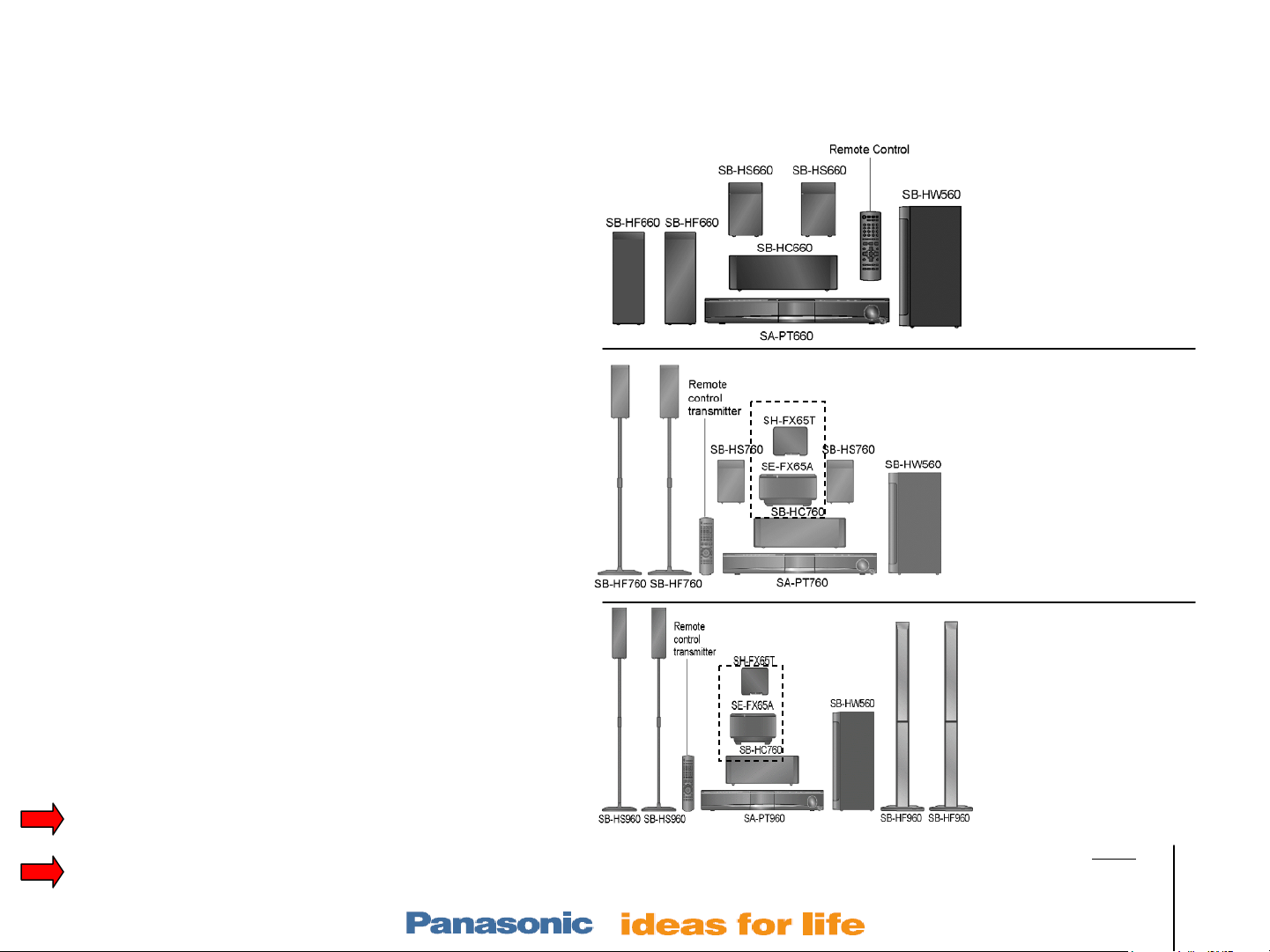
Table of Contents
Electronics –Layouts / Hints
Hints – p/n, New codes, Tests, Reset 4
Layout w test points and PS voltages 5
Wireless
SH-FX65/66 Rear Receiver Setup 8
Wireless Troubleshooting Plan 9
Testing & Paring Trans & Rec 10
Transmitter / Receiver Repair Info 11
Power ON
Power On Sequence 14
Mechanism – stacked 5 Disc model CR-14
Operation 15
Alignment 16
Troubleshooting 21
Laser Replacement (removal & install) 25
Power Supply
PS Block with isolation strategy 31
Home Theater Products Repair
center SW
T
R
SW
center
SA-PT660
SA-PT760
PS Circuit with ref voltages 32
Protection
Protection Concept (F61 & F76 codes) 34
Protection Circuitry 35
Protection Repair Procedure 36
Audio
Concept 39
Speaker Output Waveform 40
Sample Problems & Repair Methods 41
Slide # 38
T
R
center
SW
SA-PT960
Outline
Wireless
Mech
Pwr Supply
Protection
Audio
Models:
SA-PT660
SA-PT760
SA-PT960
SA-PT1060
SH-FX67, 85
Page 39

Audio Processing Concepts
Slide # 39
Outline
Wireless
Mech
Pwr Supply
Protection
Audio
Models:
SA-PT660
SA-PT760
SA-PT960
SA-PT1060
SH-FX67, 85
Page 40

Audio – Speaker Output Waveforms
Units with a digital power output IC always outputs a sine wave at the speaker terminals
Digital Scope snapshot at the Speaker Terminals
Normal “RF” waveform at the speaker
terminals even when there is no sound!
No Audio @ spk term Music or Voice Audio @ spk term
Output IC is ON * but may be muted or
no audio is input.
Spk Terminal Output = background sine wave at
1.4Vp-p @ 375kHz. Duty cycle = 50%
Average spk DC voltage = 0Vdc
Typical voice waveform
at the speaker terminals
There is a constant 1.4Vp-p minimum signal
with the digital (PAM) audio.
Background sine wave is modulated with
voice audio that averages above and
below the 0V center line (PAM).
Slide # 40
Same output with or without speakers.
* Output ICs can be turned off from the mute
input. 5V = norm, 3V = mute, 0V = Off.
PAM = Pulse Amplitude Modulation
Outline
Wireless
Mech
Pwr Supply
Protection
Audio
Models:
SA-PT660
SA-PT760
SA-PT960
SA-PT1060
SH-FX67, 85
Page 41

Sample Audio Problems – Troubleshooting Methods
Refer to the Audio simplified diagram and layout
Audio Troubleshooting Isolation Methods
1. No Audio Causes (all inputs dead)
a) Pwr Supply loss – check for + 30Vdc at pwr on. (see layout diagram)
b) No Osc input – check for 4.5Vp-p (375kHz) at pin 1 of each output IC5000-5400/pin 1.
c) Mute input – check for normal (unmute) 5Vdc at CN2009/pins 12, 13, 17.
d) Mute input – check for broken headphone jack Sw at CN2007/pin 11 [5V = hp in, 3.5V = hp out]
2. Missing 1 or more channels (remote is needed)
a) Mute – check for normal 5Vdc at each output IC5000-5400/pin 23 (last pin).
b) No Osc – check for 4.5Vp-p (375kHz) at each output IC5000-5400/pin 1.
c) Use the Audio Process diagram info to select “S Music” then scope the audio at CN2003 pins.
3. Hum - Unplug CN5050 and power the unit on.
a) Hum still present? – “Damp” board problem. The board’s gnd should not touch the chassis.
PT760/960 remote
N2QAYB 000 214
b) Hum gone? – SMPS or Main board problem. (Main transformer T5701 if lightning damage)
4. Mute Causes
a) Headphone plugged in instructs the micro t o mute the spk output (ck sw at CN2007/pin 11) .
b) Unplug the tuner (from the main board) to see if it is killing data communications.
c) Check the mute voltages at CN2009/pins 17(all spk mute), pin 13 (frt & Sw mute), pin 12 (cent
d) DVD board no communications or its 50 pin cable is defective / damaged.
5. Low volume
Normal signal levels when the volume control is max at 50 are at the audio processing concepts
diagram, lower left corner box. Vp-p Levels are with the “S Music” On and Off.
Slide # 41
& Surr mute). Normal voltage = 5Vdc. 0V = mute.
PT660 remote
N2QAYB 000 210
Outline
Wireless
Mech
Pwr Supply
Protection
Audio
Models:
SA-PT660
SA-PT760
SA-PT960
SA-PT1060
SH-FX67, 85
Page 42

Table of Contents
Electronics –Layouts / Hints
Hints – p/n, New codes, Tests, Reset 4
Layout w test points and PS voltages 5
Wireless
SH-FX65/66 Rear Receiver Setup 8
Wireless Troubleshooting Plan 9
Testing & Paring Trans & Rec 10
Transmitter / Receiver Repair Info 11
Power ON
Power On Sequence 14
Mechanism – stacked 5 Disc model CR-14
Operation 15
Alignment 16
Troubleshooting 21
Laser Replacement (removal & install) 25
Power Supply
PS Block with isolation strategy 31
Home Theater Products Repair
center SW
T
R
SW
center
SA-PT660
SA-PT760
PS Circuit with ref voltages 32
Protection
Protection Concept (F61 & F76 codes) 34
Protection Circuitry 35
Protection Repair Procedure 36
Audio
Concept 39
Speaker Output Waveform 40
Sample Problems & Repair Methods 41
Slide # 42
T
R
center
SW
SA-PT960
Outline
Wireless
Mech
Pwr Supply
Protection
Audio
Models:
SA-PT660
SA-PT760
SA-PT960
SA-PT1060
SH-FX67, 85
 Loading...