

Panasonic SC-HT850E, SC-HT800E User Manual
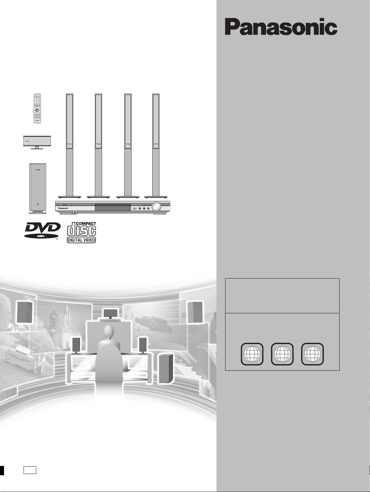
DVD Home Theater Sound System
Operating Instructions
Model No. SC-HT850
AV SYSTEM
TV VCR/AUX
SLEEP
TV/AV
TUNER/BANDDVD/CD
FL DISPLAY
DIMMER
123
PLAY MODE
MIX 2CH
456
REPEAT
7809
P.MEMORY CANCEL
S
10/
-/--
SKIP
SLOW/SEARCH
CH
TOP MENU
MENU
DIRECT
PLAY LIST
NAVIGATOR
ENTER
DISPLAY
RETURN
TV VOL
s
TV VOL
r
VOLUME
SUBWOOFER
LEVEL
MUTING
CSM SFC
CH SELECT
SSS PL C.FOCUS
TEST
FM MODE
ZOOM GROUP AUDIO
SETUP
R
AUDIO/VIDEO
Í/I
RDS SFC SELECTOR
DVD HOME THEATER SOUND SYSTEM SA-HT850
PHONES
VOLUME
OPEN/CLOSE
SUBWOOFER
DOWN UP
Region number supported by
this unit
Region numbers are allocated to this unit and
software according to where they are sold.
≥The region number of this unit is “2”.
≥The unit will play DVD-Video marked with
labels containing “2” or “ALL”.
Example:
2
2
ALL
3
5
E
Before connecting, operating or adjusting this
product, please read these instructions completely.
Please keep this manual for future reference.
RQT7026-B
Dear customer
Thank you for purchasing this product.
For optimum performance and safety, please read these instructions
carefully.
Operations in these instructions are described mainly
with the remote control, but you can do the operations on
the main unit if the controls are the same.
System SC-HT850
Main unit SA-HT850
Front and surround
speakers
Center speaker SB-PC701
Active subwoofer SB-WA340
SB-FS900
CAUTION!
THIS PRODUCT UTILIZES A LASER.
USE OF CONTROLS OR ADJUSTMENTS OR
PERFORMANCE OF PROCEDURES OTHER THAN THOSE
SPECIFIED HEREIN MAY RESULT IN HAZARDOUS
RADIATION EXPOSURE.
DO NOT OPEN COVERS AND DO NOT REPAIR YOURSELF.
REFER SERVICING TO QUALIFIED PERSONNEL.
Getting started
WARNING:
TO REDUCE THE RISK OF FIRE, ELECTRIC SHOCK OR
PRODUCT DAMAGE, DO NOT EXPOSE THIS APPARATUS
TO RAIN, MOISTURE, DRIPPING OR SPLASHING AND
THAT NO OBJECTS FILLED WITH LIQUIDS, SUCH AS
VASES, SHALL BE PLACED ON THE APPARATUS.
CAUTION!
≥ DO NOT INSTALL OR PLACE THIS UNIT IN A BOOKCASE,
BUILT-IN CABINET OR IN ANOTHER CONFINED SPACE.
ENSURE THE UNIT IS WELL VENTILATED. TO PREVENT
RISK OF ELECTRIC SHOCK OR FIRE HAZARD DUE TO
OVERHEATING, ENSURE THAT CURTAINS AND ANY
OTHER MATERIALS DO NOT OBSTRUCT THE
VENTILATION VENTS.
≥ DO NOT OBSTRUCT THE UNIT’S VENTILATION
OPENINGS WITH NEWSPAPERS, TABLECLOTHS,
CURTAINS, AND SIMILAR ITEMS.
≥ DO NOT PLACE SOURCES OF NAKED FLAMES, SUCH
AS LIGHTED CANDLES, ON THE UNIT.
≥ DISPOSE OF BATTERIES IN AN ENVIRONMENTALLY
FRIENDLY MANNER.
THIS UNIT IS INTENDED FOR USE IN MODERATE
CLIMATES.
This product may receive radio interference caused by mobile
telephones during use. If such interference is apparent, please
increase separation between the product and the mobile
telephone.
SUOMI
VAROITUS!
LAITTEEN KÄYTTÄMINEN MUULLA KUIN TÄSSÄ
KÄYTTÖOHJEESSA MAINITULLA TAVALLA SAATTAA
ALTISTAA KÄYTTÄJÄN TURVALLISUUSLUOKAN 1
YLITTÄVÄLLE NÄKYMÄTTÖMÄLLE LASERSÄTEILYLLE.
VAROITUS:
TULIPALO-, SÄHKÖISKUVAARAN TAI TUOTETTA
KOHTAAVAN MUUN VAHINGON VÄHENTÄMISEKSI EI
LAITETTA SAA ALTISTAA SATEELLE, KOSTEUDELLE,
VESIPISAROILLE TAI ROISKEELLE, EIKÄ NESTETTÄ
SISÄLTÄVIÄ ESINEITÄ, KUTEN ESIMERKIKSI
MALJAKOITA, SAA ASETTAA LAITTEEN PÄÄLLE.
VAROITUS!
≥ ÄLÄ ASENNA TAI LAITA TÄTÄ LAITETTA
KABINETTITYYPPISEEN KIRJAKAAPPIIN TAI MUUHUN
SULJETTUUN TILAAN, JOTTA TUULETUS ONNISTUISI.
VARMISTA, ETTÄ VERHO TAI MIKÄÄN MUU MATERIAALI
EI HUONONNA TUULETUSTA, JOTTA VÄLTETTÄISIIN
YLIKUUMENEMISESTA JOHTUVA SÄHKÖISKU- TAI
TULIPALOVAARA.
≥ ÄLÄ PEITÄ LAITTEEN TUULETUSAUKKOJA
SANOMALEHDELLÄ, PÖYTÄLIINALLA, VERHOLLA TAI
MUULLA VASTAAVALLA ESINEELLÄ.
≥ ÄLÄ ASETA PALAVAA KYNTTILÄÄ TAI MUUTA
AVOTULEN LÄHDETTÄ LAITTEEN PÄÄLLE.
≥ HÄVITÄ PARISTOT LUONTOA
VAHINGOITTAMATTOMALLA TAVALLA.
TÄMÄ LAITE ON TARKOITETTU KÄYTETTÄVÄKSI
LEUDOSSA ILMASTOSSA.
NORSK
ADVARSEL!
DETTE PRODUKTET ANVENDER EN LASER.
BETJENING AV KONTROLLER, JUSTERINGER ELLER
ANDRE INNGREP ENN DE SOM ER BESKREVET I DENNE
BRUKSANVISNING, KAN FØRE TIL FARLIG BESTRÅLING.
DEKSLER MÅ IKKE ÅPNES, OG FORSØK ALDRI Å
REPARERE APPARATET PÅ EGENHÅND. ALT SERVICE
OG REPARASJONSARBEID MÅ UTFØRES AV
KVALIFISERT PERSONELL.
RQT7026
2
(Inside of product)
(Tuotteen sisällä)
(Produktets innside)
CLASS 1
LASER PRODUCT
LUOKAN 1 LASERLAITE
KLASS 1 LASER APPARAT
ADVARSEL:
FOR Å REDUSERE FAREN FOR BRANN, ELEKTRISK STØT
ELLER SKADER PÅ PRODUKTET, MÅ DETTE APPARATET
IKKE UTSETTES FOR REGN, FUKTIGHET, VANNDRÅPER
ELLER VANNSPRUT. DET MÅ HELLER IKKE PLASSERES
GJENSTANDER FYLT MED VANN, SLIK SOM
BLOMSTERVASER, OPPÅ APPARATET.
ADVARSEL!
≥ APPARATET MÅ IKKE PLASSERES I EN BOKHYLLE, ET
INNEBYGGET KABINETT ELLER ET ANNET LUKKET
STED HVOR VENTILASJONSFORHOLDENE ER
UTILSTREKKELIGE. SØRG FOR AT GARDINER ELLER
LIGNENDE IKKE FORVERRER
VENTILASJONSFORHOLDENE, SÅ RISIKO FOR
ELEKTRISK SJOKK ELLER BRANN FORÅRSAKET AV
OVERHETING UNNGÅS.
≥ APPARATETS VENTILASJONSÅPNINGER MÅ IKKE
DEKKES TIL MED AVISER, BORDDUKER, GARDINER OG
LIGNENDE.
≥ PLASSER IKKE ÅPEN ILD, SLIK SOM LEVENDE LYS,
OPPÅ A PPARATET.
≥ BRUKTE BATTERIER MÅ KASSERES UTEN FARE FOR
MILJØET.
DETTE APPARATET ER BEREGNET TIL BRUK UNDER
MODERATE KLIMAFORHOLD.
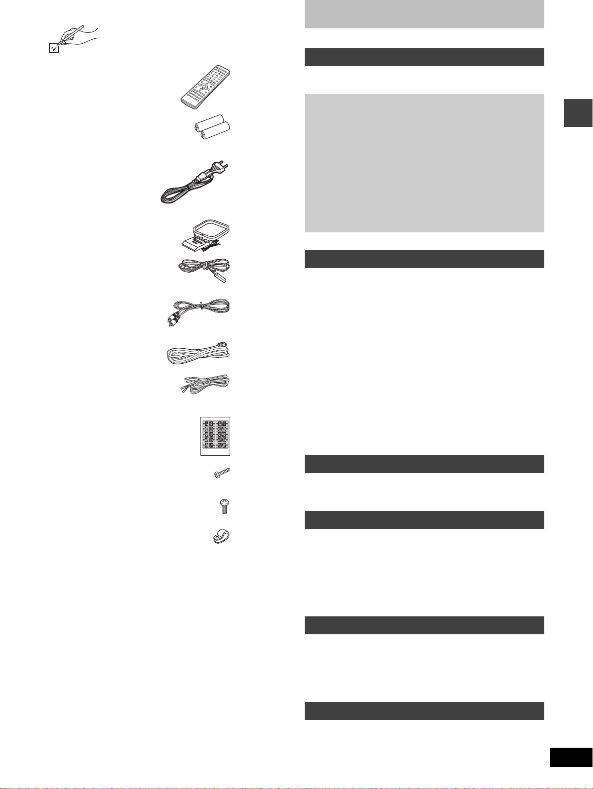
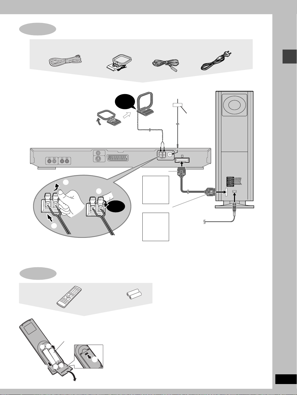
Accessories
Please check and identify the supplied accessories.
Table of contents
∏ 1 Remote control
(EUR7623XA0)
∏ 2 Batteries
for remote control
∏ 1 AC mains lead
∏ 1 AM loop antenna
∏ 1 FM indoor antenna
∏ 1 Video cable
∏ 1 System cable
∏ 5 Speaker cables
3k4-m cables
2k10-m cables
∏ 1 Sheet of speaker-cable stickers
Getting started
Accessories. . . . . . . . . . . . . . . . . . . . . . . . . . . . . . . . . . . . 3
Disc information . . . . . . . . . . . . . . . . . . . . . . . . . . . . . . . . 4
Simple setup
STEP1
STEP2
STEP3
STEP4
STEP5
STEP6
Other speaker setup options
(Center speaker only) . . . . . . . . . . . . . . . . . . . . . . . . . . 10
STEP7
Control reference guide . . . . . . . . . . . . . . . . . . . . . . . . . 12
Assembly and connection of front and
surround speakers. . . . . . . . . . . . . . . . . . . . .5
Locating . . . . . . . . . . . . . . . . . . . . . . . . . . . . .6
Connections for front, surround,
and center speakers to the subwoofer . . . .7
Television . . . . . . . . . . . . . . . . . . . . . . . . . . . .8
Connecting the subwoofer, antennas, and
AC mains lead . . . . . . . . . . . . . . . . . . . . . . . .9
The remote control. . . . . . . . . . . . . . . . . . . . .9
QUICK SETUP. . . . . . . . . . . . . . . . . . . . . . . .11
Disc operations
Discs—Basic play. . . . . . . . . . . . . . . . . . . . . . . . . . . . . . 13
Starting play from a selected item. . . . . . . . . . . . . . . . . . . . . . . 14
Position Memory function . . . . . . . . . . . . . . . . . . . . . . . . . . . . . 14
Skipping items/Fast forward and rewind—SEARCH . . . . . . . . . 15
Slow-motion play/Frame-by-frame viewing. . . . . . . . . . . . . . . . 15
Selecting groups to play . . . . . . . . . . . . . . . . . . . . . . . . . . . . . . 15
Discs—Convenient functions . . . . . . . . . . . . . . . . . . . . 16
Repeat play/A-B repeat play . . . . . . . . . . . . . . . . . . . . . . . . . . . 16
All group play/Program play/Random play . . . . . . . . . . . . . . . . 17
Marking places to play again/Variable Zoom function. . . . . . . . 18
Soundtracks/Subtitles . . . . . . . . . . . . . . . . . . . . . . . . . . . . . . . . 19
WMA/MP3 and CD text navigation menus . . . . . . . . . . 20
Playing the programs or play lists on DVD-RAM. . . . . 22
Selecting a program to play—DIRECT NAVIGATOR . . . . . . . . 22
Using the play list menu . . . . . . . . . . . . . . . . . . . . . . . . . . . . . . 22
Using GUI (Graphical User Interface) screens. . . . . . . 23
Common procedures/Progress indicator. . . . . . . . . . . . . . . . . . 23
Disc information/Unit information . . . . . . . . . . . . . . . . . . . . . . . 24
Getting started
∏ 8 Silver screws
∏ 4 Black screws
∏ 4Clips
[Note]
The included AC mains lead is for use with this unit only. Do not use
it with other equipment.
Radio operations
The radio . . . . . . . . . . . . . . . . . . . . . . . . . . . . . . . . . . . . . 26
Manual tuning/Preset tuning . . . . . . . . . . . . . . . . . . . . . . . . . . . 26
RDS broadcasting . . . . . . . . . . . . . . . . . . . . . . . . . . . . . . . . . . . 27
Sound field/sound quality operations
Sound field . . . . . . . . . . . . . . . . . . . . . . . . . . . . . . . . . . . 27
Dolby Digital and DTS. . . . . . . . . . . . . . . . . . . . . . . . . . . . . . . . 27
Dolby Pro Logic/Speaker level adjustments . . . . . . . . . . . . . . . 28
Super Surround . . . . . . . . . . . . . . . . . . . . . . . . . . . . . . . . . . . . . 28
Sound Field Control/Center Focus . . . . . . . . . . . . . . . . . . . . . . 29
Custom Sound Memory—Store the sound settings . . . . . . . . . 29
Sound quality . . . . . . . . . . . . . . . . . . . . . . . . . . . . . . . . . 29
Adjusting the bass/Re-master—Enjoying more natural sound. . .29
Other functions
Convenient functions . . . . . . . . . . . . . . . . . . . . . . . . . . . 30
Muting the volume/Dimming the display . . . . . . . . . . . . . . . . . . 30
The sleep timer/Using headphones. . . . . . . . . . . . . . . . . . . . . . 30
Changing settings. . . . . . . . . . . . . . . . . . . . . . . . . . . . . . 31
Operating a television or video cassette recorder . . . 34
Optional antenna connections . . . . . . . . . . . . . . . . . . . 35
Reference
Troubleshooting guide. . . . . . . . . . . . . . . . . . . . . . . . . . 36
Maintenance . . . . . . . . . . . . . . . . . . . . . . . . . . . . . . . . . . 37
Glossary. . . . . . . . . . . . . . . . . . . . . . . . . . . . . . . . . . . . . . 38
Safety precautions . . . . . . . . . . . . . . . . . . . . . . . . . . . . . 38
Specifications . . . . . . . . . . . . . . . . . . . . . . . . . . . . . . . . . 39
RQT7026
3
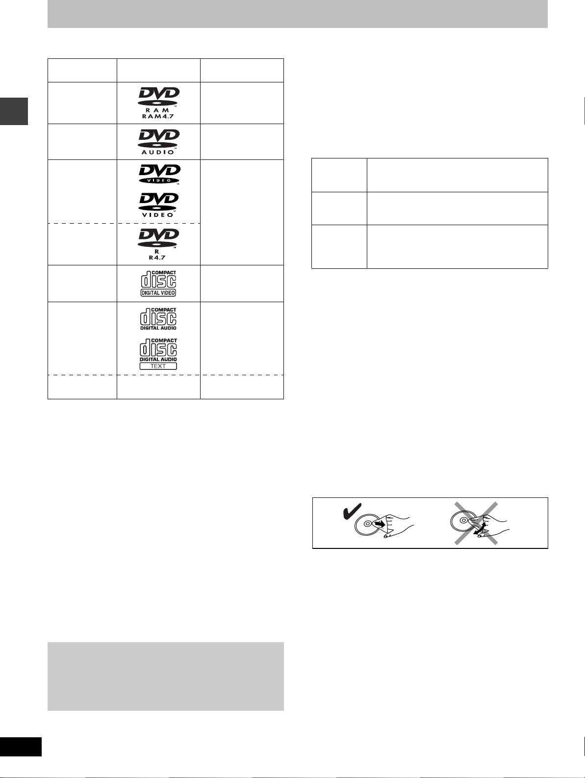
Disc information
∫ Discs that can be played
Disc type Logo Indication used in
instructions
DVD-RAM [RAM]
DVD-Audio [DVD-A]
DVD-Video [DVD-V]
Getting started
DVD-R
Video CD [VCD]
CD [CD]
Including CD text
CD-R/RW — [WMA]
[MP3]
≥Use discs with the above logos and that conform to specifications.
The unit cannot play other discs correctly.
≥Do not use irregularly shaped discs (e.g. heart-shaped), as these
can damage the unit.
∫ Discs that cannot be played
DVD-ROM, CD-ROM, CDV, CD-G, iRW, DVD-RW, CVD, SVCD,
SACD, Divx Video Discs and Photo CD.
∫ Disc structure
Disc structure and the labels given to the items on discs depend on
the disc type.
Track: the smallest division on DVD-Audio, CDs and Video CDs,
or a single WMA/MP3 file.
Chapter: the smallest division on DVD-Video.
Group: collections of tracks on DVD-Audio and equivalent to
folders or albums on data discs.
Title: the largest division on DVD-Video, usually an entire
movie.
Program: the division on DVD-RAM equivalent to a single
recording.
Play list: a group of scenes on DVD-RAM.
Scene: DVD-RAM program sections specified and grouped into
play lists on a DVD video recorder.
Playing DVDs and Video CDs
The producer of these discs can control how they are played so
you may not always be able to control play as described in these
operating instructions (for example if the play time is not
displayed or if a Video CD has menus). Read the disc’s
instructions carefully.
∫ CD-R and CD-RW discs
This unit can play CD-R/RW (audio recording disc) recorded with
CD-DA, video CD, WMA or MP3. Finalize
§
the disc after recording.
∫ DVD-R discs
Panasonic DVD-R recorded and finalized§ on a Panasonic DVD
video recorder are played as DVD-Video on this unit.
§
A process that allows play on compatible equipment.
∫ DVD-RAM discs
DVD-RAM discs must meet the following conditions for this unit to be
able to play them.
Ty pe ≥Non-cartridge discs
Capacity ≥12 cm 9.4 GB (double-sided) and 4.7 GB
Recording
format
≥Remove TYPE 2 and 4 discs from their cartridges before use, then
return them when you are finished. Read the instructions for the
disc carefully.
≥Do not allow the disc to become dirty or scratched. Store discs in
their cartridges and ensure the disc label and cartridge label face
the same way.
≥Some parts of the disc, for example where one program ends and
another begins, may not play smoothly.
≥Discs that can be removed from their
cartridges (TYPE 2 and 4)
(single-sided)
≥8 cm 2.8 GB (double-sided)
Discs recorded with DVD video recorders, DVD
video cameras, personal computers, etc., using
Version 1.1 of the Video Recording Format (a
unified video recording standard).
[Note]
It may not be possible to play CD-R, CD-RW, DVD-R and DVD-RAM
in all cases due to the type of disc or condition of the recording.
∫ Video systems
This unit can play both the PAL and NTSC video systems. To view
PAL or NTSC, however, your television must match the system used
on the disc.
PAL discs cannot be correctly viewed on an NTSC television. NTSC
can be correctly viewed on a PAL television by converting the video
signal to PAL 60 (➡ page 31, Video—NTSC Disc Output).
∫ To clean discs
DVD-Audio, DVD-Video, Video CD, CD
Wipe with a damp cloth and then wipe dry.
DVD-RAM, DVD-R
≥Clean with an optional DVD-RAM/PD disc cleaner (LF-K200DCA1,
where available).
≥Never use cloths or cleaners for CDs etc.
∫ Handling precautions
≥Do not write on the label side with a ball-point pen or other writing
instrument.
≥Do not use record cleaning sprays, benzine, thinner, static
electricity prevention liquids or any other solvent.
≥Do not attach labels or stickers to discs. (Do not use discs with
exposed adhesive from tape or left over peeled-off stickers.)
≥Do not use scratch-proof protectors or covers.
≥Do not use discs printed with label printers available on the market.
RQT7026
4
Simple setup
1
STEP
1
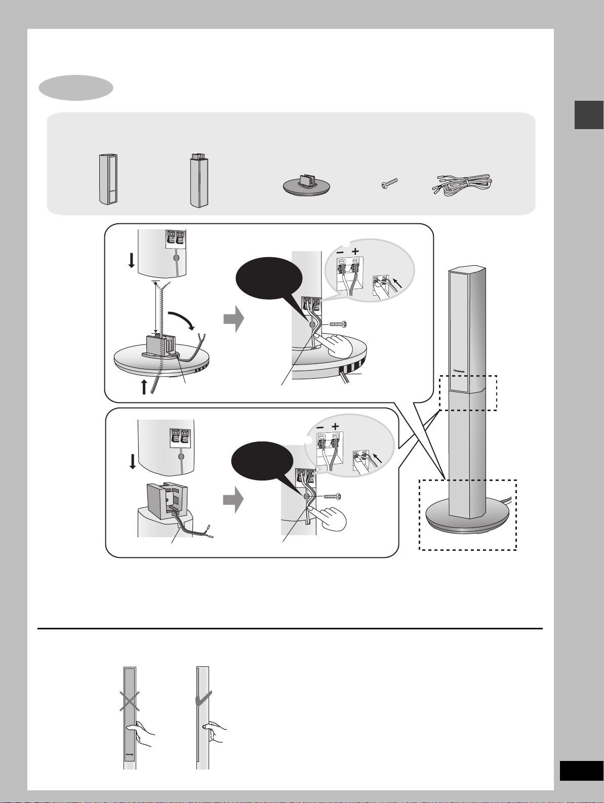
Assembly and connection of front and surround speakers
4 Speaker units 4 Stands
4
Approx.
120 mm
2
31
Fit into groove. Place into groove.
4 Bases
Confirm screw
is securely
fastened.
7
8 Silver screws
6
5
Copper
_:
Silver
`:
Position wire
in grooves as
necessary
8
avoiding
knots.
Speaker cables
≥2k4-m cables
≥2k10-m cables
Simple setup
Assembled
_:
Confirm screw
4
2
2
15
Fit into groove.
≥You can attach the speakers directly to their bases (if you want to put them on shelves, for example).
[Note]
≥Never short-circuit positive (i) and negative (j) speaker wires.
≥Be sure to connect only positive (copper) wires to positive (i) terminals and negative (silver) wires to negative (j) terminals.
Incorrect connection can damage the speakers.
is securely
fastened.
3
Place into groove.
`:
Copper
Silver
Caution
Hold the speakers by the sides. Applying pressure to the front net can damage the speaker.
RQT7026
5
STEP
2
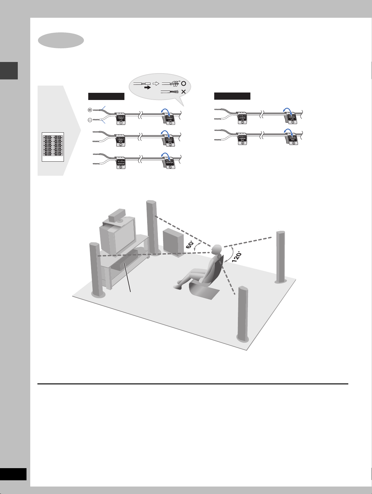
Locating
1 Attaching the stickers to the speaker cables
Attach the speaker-cable stickers to make connection easier.
Short cables
1 Sheet of
speaker-cable
Simple setup
stickers
Copper
FRONT
(L)
Silver
FRONT
(R)
CENTER
Long cables
SURROUND
(L)
SURROUND
(R)
2 Position the speakers
Setup example
CENTER
FRONT
(L)
FRONT
(R)
SUBWOOFER
SURROUND
(R)
RQT7026
6
Main unit
SURROUND
(L)
≥The front and surround speakers are the same. Use those you have connected the short cords to as front speakers and those you have
connected the long cords to as surround speakers.
≥Place the front, center, and surround speakers at approximately the same distance from the seating position. The angles in the diagram are
approximate.
≥Use only supplied speakers
Using other speakers can damage the unit and sound quality will
be negatively affected.
≥Set the speakers up on an even surface to prevent them from
falling. Take proper precautions to prevent the speakers from
falling if you cannot set them up on an even surface.
Positioning for best effect
How you set up your speakers can affect the bass and the sound
field. Note the following points.
≥Place speakers on flat secure bases.
≥Placing speakers too close to floors, walls, and corners can result
in excessive bass. Cover walls and windows with thick curtain.
Main unit
Keep your speakers at least 10 mm away from the system for
proper ventilation.
Center speaker
≥You can also put this speaker directly under the television.
≥Vibration caused by the center speaker can disrupt the picture if it
is placed directly on the television. Put the center speaker on a
rack or shelf.
Subwoofer
Place to the right of the television, on the floor or a sturdy shelf so
that it won’t cause vibration.
Leave 10 cm on the right for the woofer to be effective. Leave
10 cm at the rear for ventilation.
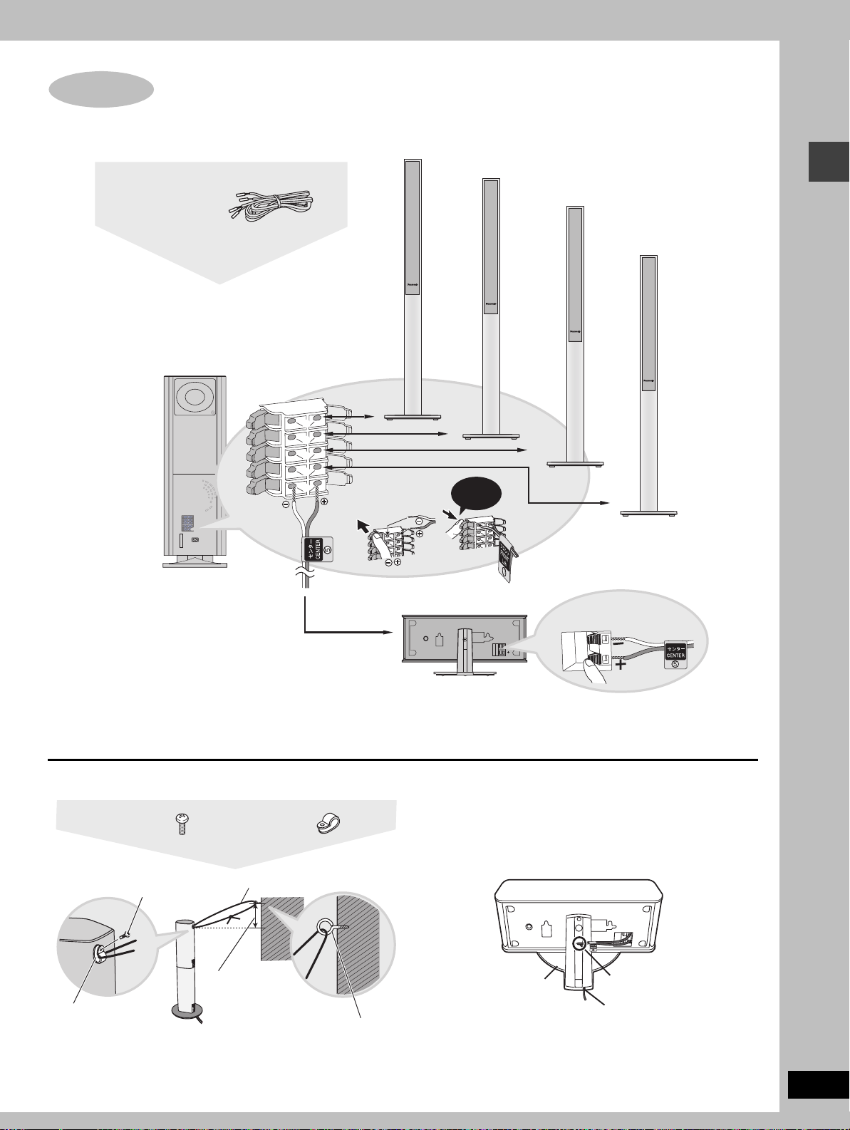
STEP
3
1 short cable
(for Center speaker)
Connections for front, surround,
SUBWOOFER
6
and center speakers to the subwoofer
1 FRONT (L)
2 FRONT (R)
3 SURROUND (L)
1
2
3
4
5
Click!
4 SURROUND (R)
Simple setup
5 CENTER
[Note]
≥Never short-circuit positive (i) and negative (j) speaker wires.
≥Be sure to connect only positive (copper) wires to positive (i) terminals and negative (silver) wires to negative (j) terminals.
Incorrect connection can damage the speakers.
∫ Preventing the speakers from falling over
(Front and surround speakers)
4 Black screws
Screw
Clip
[Note]
Consult a qualified building contractor when attaching the speakers to
wall. Improper attachment may result in damage to the wall and
speakers.
4 Clips
String (not included)
Approx. 150 mm
Screw (not included)
∫ Keeping the cables out of the way
(Center speaker)
Pass the cables through the holes in the stand to keep them out
of the way.
Stand
_:
`:
Copper
Silver
1 Pass the cable
through the hole.
2 Pass through the
cutout in the base.
RQT7026
7
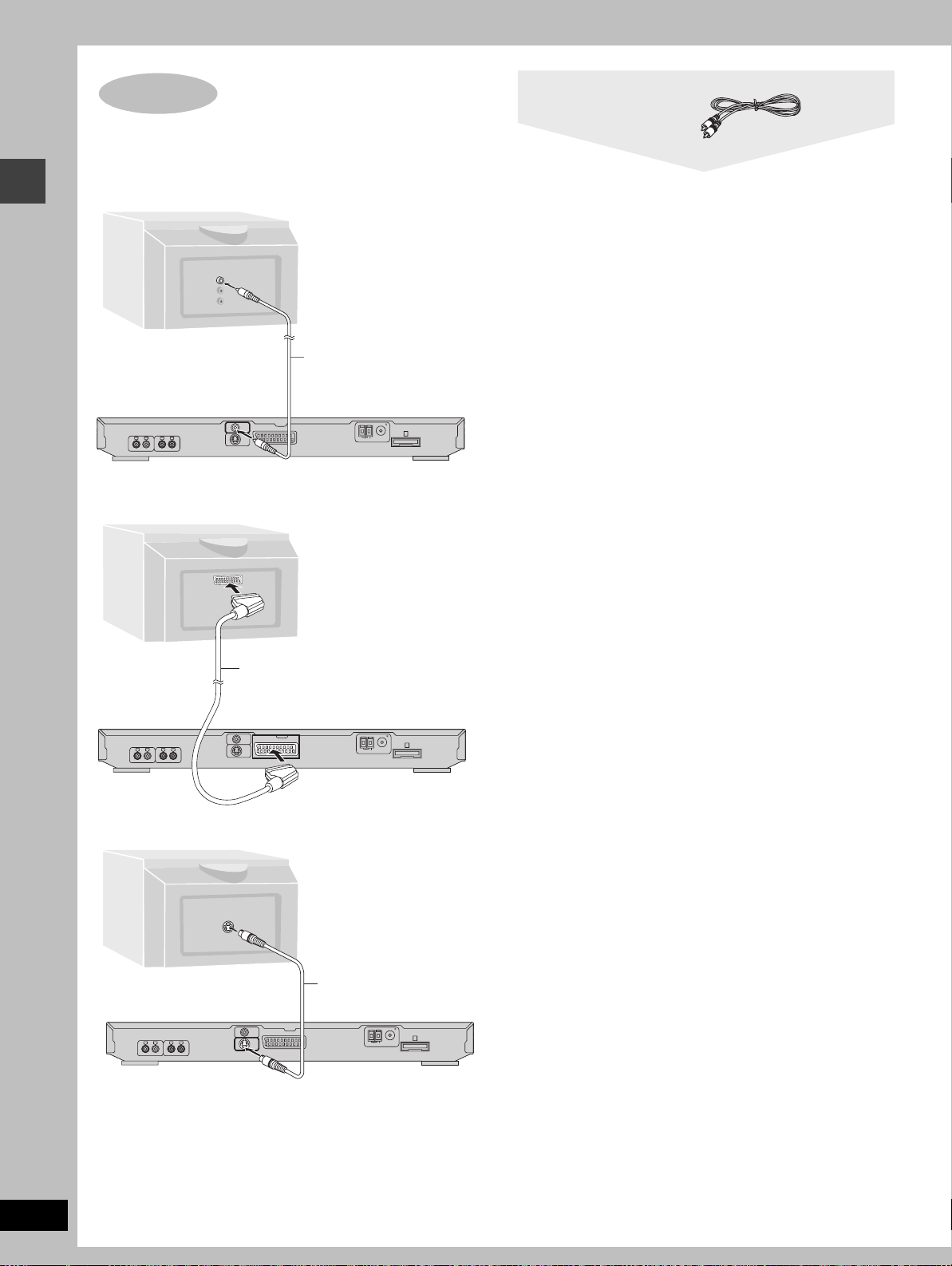
STEP
4
Television
Video cable
∫ Connecting a television with a VIDEO IN terminal
Connect directly to your television.
Do not connect the unit through a video cassette recorder,
because the picture may not be played correctly due to the
copy guard.
VIDEO
IN
Television
(not included)
Simple setup
Video cable
(included)
FM ANT (75 )
RL RL
TV AUDIO INVCR AUDIO IN/AUX
VIDEO
AV
OUT
S-VIDEO
OUT
AM ANT
A
EXTLOOP
∫ Connecting a television with SCART terminal
AV
21-pin SCART cable
(not included)
FM ANT (75 )
RL RL
TV AUDIO INVCR AUDIO IN/AUX
VIDEO
AV
OUT
S-VIDEO
OUT
AM ANT
A
EXTLOOP
∫ Connecting a television with an S-VIDEO IN terminal
S VIDEO
IN
SCART terminal
To improve picture quality, you can change the video
signal output from the AV terminal from “Video” to either
“S-Video” or “RGB” to suit the type of television you are
using (➡ page 11, QUICK SETUP or page 31, Video—AV
Output).
S VIDEO OUT terminal
The S video terminal achieves a more vivid picture than
the VIDEO OUT terminal by separating the chrominance
(C) and luminance (Y) signals. (Actual results depend on
the television.)
RQT7026
8
RL RL
TV AUDIO INVCR AUDIO IN/AUX
S-video cable
(not included)
FM ANT (75 )
VIDEO
AV
OUT
S-VIDEO
OUT
AM ANT
A
EXTLOOP
STEP
6
5
Connecting the subwoofer, antennas, and AC mains lead
System cable AM loop antenna FM indoor antenna
Connect the AC mains lead after all
other connections are complete.
Stand the antenna up on its base.
Keep loose antenna cord away from
other wires and cords.
RL RL
TV AUDIO INVCR AUDIO IN/AUX
1
2
3
VIDEO
OUT
S-VIDEO
OUT
AM loop antenna
Click!
AV
Click!
FM ANT (75 )
AM ANT
EXTLOOP
Catch up
To
disconnect
Press the
catch and
pull out.
Catch to the right
To
disconnect
Press the
catch and
pull out.
FM indoor
antenna
Adhesive tape
Fix the other end
of the antenna
where reception is
best.
A
To household
mains socket
AC mains lead
System cable
AC mains lead
Subwoofer
1
L
2
R
3
L
4
R
5
Simple setup
A
Conserving power
The unit consumes power [approx. 0.7 W (Subwoofer)] even when
it is turned off with [Í]. To save power when the unit is not to be
used for a long time, unplug it from the household mains socket.
STEP
Remote control
+
The remote control
≥Insert so the poles (i and j)
match those in the remote
control.
≥Do not use rechargeable type
batteries.
-
R6,AA,UM-3
3
Batteries
1
+
-
3
2
Remember to reset the radio stations and any other memory items
before using the unit again.
Information you enter into the unit’s memory remains intact for up
to 2 weeks after the AC mains lead is disconnected.
Do not;
≥mix old and new batteries.
≥use different types at the same time.
≥heat or expose to flame.
≥take apart or short circuit.
≥attempt to recharge alkaline or manganese batteries.
≥use batteries if the covering has been peeled off.
Mishandling of batteries can cause electrolyte leakage which
can damage items the fluid contacts and may cause a fire.
Remove if the remote control is not going to be used for a long
period of time. Store in a cool, dark place.
∫ Use
Aim at the sensor, avoiding obstacles, at a maximum range of
7 m directly in front of the unit.
RQT7026
9
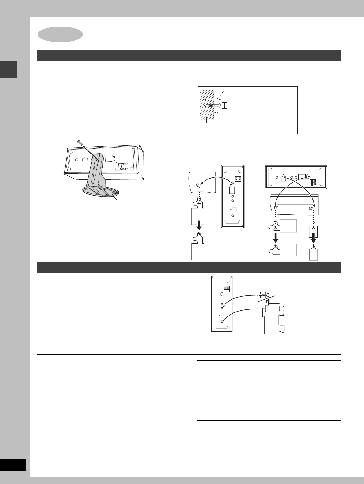
Other speaker setup options (Center speaker only)
Attaching to a wall
[Note]
The wall or pillar on which the speakers are to be attached should
be capable of supporting 10 kg per screw.
1 Remove the stand.
BEFORE REMOVING THE STAND
≥Take the speaker cable out of the stand’s hole if it is
threaded through.
Simple setup
≥Lay the speaker on a soft cloth.
Unscrew the screw with a Phillips-head screwdriver.
2 Screw a screw (not included) into the
wall.
30–35 mm
‰7.5–9.4 mm
8–11 mm
Wall
3 Fit the speaker securely onto the
screw with the hole or holes.
Vertical Horizontal
Stand
100 mm
RQT7026
10
Fitting speaker stands (optional)
Preparation
Remove the stand (➡ step 1 above).
Ensure the stands meet these conditions before purchasing them.
≥Observe the diameter and length of the screws and the distance
between screws as shown in the diagram.
≥The stands must be able to support over 10 kg.
≥The stands must be stable even if the speakers are in a high
position.
Notes on speaker use
≥You can damage your speakers and shorten their useful life if you
play sound at high levels over extended periods.
≥Reduce the volume in the following cases to avoid damage.
–When playing distorted sound.
–When the speakers are receiving howling from a record player,
noise from FM broadcasts, or continuous signals from an
oscillator, test disc, or electronic instrument.
–When adjusting the sound quality.
–When turning the unit on or off.
If irregular coloring occurs on your television
These speakers are designed to be used close to a television, but
the picture may be affected with some televisions and set-up
combinations.
If this occurs, turn the television off for about 30 minutes.
The television’s demagnetizing function should correct the
problem. If it persists, move the speakers further away from the
television.
5 mm, pitch 0.8 mm
60 mm
Speaker stand
(not included)
Attach the stands
with these holes.
Caution
≥Use the speakers only with the recommended system.
Failure to do so may lead to damage to the amplifier
and/or the speakers, and may result in the risk of fire.
Consult a qualified service person if damage has
occurred or if you experience a sudden change in
performance.
≥Do not attempt to attach these speakers to walls using
methods other than those described in this manual.
Plate thickness plus 7 to
10 mm
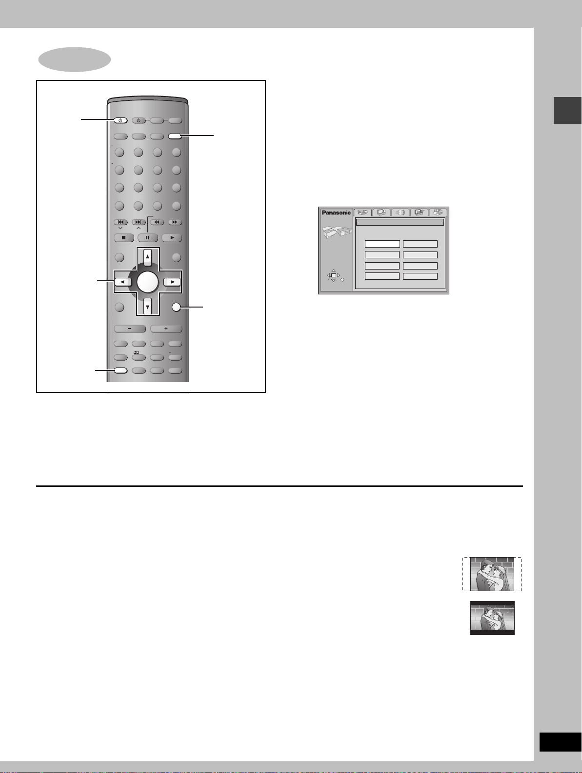
STEP
7
1
4–7
QUICK SETUP
AV SYSTEM
TV VCR /AUX
SLEEP
FL DISPLAY
DIMMER
PLAY MODE
MIX 2CH
REPEAT
POSITION
MEMORY
TOP MENU
DIRECT
NAVIGATOR
DISPLAY
TV VOL
MUTING
S.SRND PL C.FOCUS
FM MODE
SETUP
TUNER/BAND DVD/CD
TV/AV
123
456
7809
CANCEL
SKIP
SLOW/SEARCH
CH
ENTER
s
VOLUME
C.S.M. SFC
ZOOM GROUP AUDIO
S
10/
-/--
MENU
PLAY LIST
RETURN
TV VOL
SUBWOOFER
LEVEL
CH SELECT
TEST
r
2
RETURN
3, 7
The QUICK SETUP screen appears when you press [SETUP] the
first time after purchase and assists you to make necessary
settings. You can access this screen again later if you need to
(➡ page 31, Others—QUICK SETUP).
Preparation
Turn on the television and select the appropriate video input on the
television to suit the connections for the unit.
1 Press [Í] to turn on the unit.
2 Press [DVD/CD] to select “DVD/CD”
as the source.
3 Press [SETUP] to show the QUICK
SETUP screen.
SETUP
SELECT
ENTER RETURN
QUICK SETUP
Select the menu language.
English
Deutsch
Español
Svenska
Français
Italiano
Português
Nederlands
4 Press [3, 4, 2, 1] to select the
menu language and press [ENTER].
5 Press [3, 4] to select “Yes” to
continue and press [ENTER].
6 Press [3, 4, 2, 1] to select the item
and press [ENTER].
≥Audio Language (➡ page 31)
≥Subtitle Language (➡ page 31)
≥TV Type (➡ below)
≥TV Aspect (➡ below )
≥AV Output (➡ page 31)
7 Press [ENTER] and then [SETUP] to
end the settings.
Simple setup
To return to the previous screen
Press [RETURN].
∫ TV Type
Select to suit the type of television.
≥Standard (Direct View TV) (factory preset)
≥CRT Projector
≥LCD TV/Projector
≥Projection TV
≥Plasma TV
∫ TV Aspect
Select “4:3” (regular) or “16:9” (widescreen) to suit your
television.
If you have a regular 4:3 television, you can also select how video
on some discs is shown (➡ page 31, Video—TV Aspect).
≥4:3 Pan&Scan (factory preset)
Widescreen software is expanded to fill the
screen of a 4:3 aspect television (unless
prohibited by the producer of the disc).
≥4:3 Letterbox
Widescreen software is shown in the
letterbox style on a 4:3 aspect television.
RQT7026
11
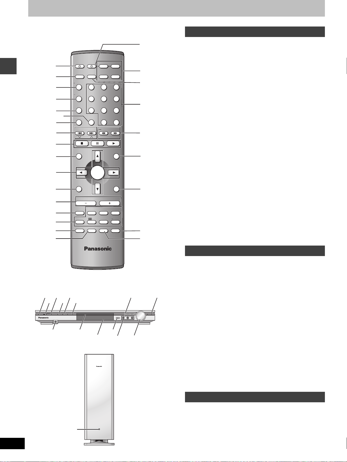
Control reference guide
Remote control
B
1 Standby/on switch [Í] . . . . . . . . . . . . . . . . . . . . . . . . . . . . . .11
2 Sleep button [SLEEP] . . . . . . . . . . . . . . . . . . . . . . . . . . . . . . .30
3 FL display, Dimmer button [FL DISPLAY, –DIMMER] . . .27, 30
AV SYSTEM
1
2
3
SLEEP
FL DISPLAY
DIMMER
PLAY MODE
MIX 2CH
4
6
REPEAT
POSITION
MEMORY
SKIP
CH
5
Getting started
7
8
TV VCR/AUX
TV/AV
TUNER/BAND DVD/CD
123
456
7809
CANCEL
S
10/
SLOW/SEARCH
-/--
C
D
E
F
9
MENU
PLAY LIST
G
:
;
TOP MENU
DIRECT
NAVIGATOR
ENTER
4 Play mode, Mix 2ch button
[PLAY MODE, –MIX 2CH] . . . . . . . . . . . . . . . . . . . . . . . . .17, 27
5 Repeat button [REPEAT]. . . . . . . . . . . . . . . . . . . . . . . . . . . . .16
6 Cancel button [CANCEL] . . . . . . . . . . . . . . . . . . . . . . . . . . . .17
7 Position memory button [POSITION MEMORY] . . . . . . . . . .14
8 Skip, Preset channel, TV channel buttons
[: 9, SKIP, X CH W] . . . . . . . . . . . . . . . . . . . . . .15, 26, 34
9 Basic operation buttons . . . . . . . . . . . . . . . . . . . . . . . . . . . . .13
: Top menu, Direct navigator button
[TOP MENU, DIRECT NAVIGATOR] . . . . . . . . . . . . . . . . .13, 22
; Cursor buttons [3, 4, 2, 1], Enter button [ENTER] . . . . .11
< Display, TV volume down button
[DISPLAY, TV VOLs] . . . . . . . . . . . . . . . . . . . . . . . . . . . . .23, 34
= Volume buttons [s, r, VOLUME] . . . . . . . . . . . . . . . . . . . . . .13
> Muting button [MUTING] . . . . . . . . . . . . . . . . . . . . . . . . . . . . .30
? Sound field, sound quality buttons . . . . . . . . . . . . . . . . .28, 29
@ FM mode, Setup button [FM MODE, SETUP] . . . . . . . . .11, 26
A Zoom button [ZOOM] . . . . . . . . . . . . . . . . . . . . . . . . . . . . . . .18
B AV system standby/on button [Í, AV SYSTEM]. . . . . . . . . .34
C Source select buttons
≥Face towards this unit to change the source.
RETURN
TV VOL
SUBWOOFER
LEVEL
CH SELECT
TEST
r
H
≥Press [TV] or [VCR/AUX] first to operate a Panasonic television
or video cassette recorder (➡ page 34).
D TV/AV button [TV/AV] . . . . . . . . . . . . . . . . . . . . . . . . . . . . . . .34
E Numbered buttons [1–9, 0, S10/-/--] . . . . . . . . . . . . . . . . . . .13
F Slow/search, Tuning buttons
[6, 5 SLOW/SEARCH] . . . . . . . . . . . . . . . . . . . . . . . .15, 26
G Menu, Play list button [MENU, PLAY LIST] . . . . . . . . . . .13, 22
H Return, TV volume up button [RETURN, TV VOLr] . . . .11, 34
I
J
I Audio button [AUDIO] . . . . . . . . . . . . . . . . . . . . . . . . . . . . . . .19
J Group button [GROUP] . . . . . . . . . . . . . . . . . . . . . . . . . . . . . .15
<
=
>
?
@
A
DISPLAY
s
TV VOL
FM MODE
VOLUM E
MUTING
C.S.M. SFC
S.SRND PL C.FOCUS
ZOOM GROUP AUDIO
SETUP
RQT7026
12
1
K
Í/I
N
L
M
RDS SFC SELECTOR
DVD HOME THEATER SOUND SYSTEM SA-HT850
PHONES
R
X
O
S
T
Main unit
1 Standby/on switch [Í/I] . . . . . . . . . . . . . . . . . . . . . . . . . . . . .11
Press to switch the unit from on to standby mode or vice versa.
In standby mode, the unit is still consuming a small amount of
power.
K Standby/on indicator
P
Q
When the unit is connected to the AC mains supply, this indicator
lights up in standby mode and goes out when the unit is turned
VOLUME
OPEN/CLOSE
SUBWOOFER
DOWN UP
on.
L Remote control signal sensor
M RDS button [RDS] . . . . . . . . . . . . . . . . . . . . . . . . . . . . . . . . . .27
N SFC button [SFC]. . . . . . . . . . . . . . . . . . . . . . . . . . . . . . . . . . .29
U
V
W
O Source select button [SELECTOR]
DVD/CD>FM>AM>TV>VCR/AUX
P Skip, Preset channel buttons [: 9] . . . . . . . . . . . .15, 26
Q Subwoofer level button [SUBWOOFER] . . . . . . . . . . . . . . . .29
R Headphone jack [PHONES] . . . . . . . . . . . . . . . . . . . . . . . . . .30
S Disc tray . . . . . . . . . . . . . . . . . . . . . . . . . . . . . . . . . . . . . . . . . .13
T Display
U Open/close button [<, OPEN/CLOSE]. . . . . . . . . . . . . . . . . .13
V Basic operation buttons . . . . . . . . . . . . . . . . . . . . . . . . . . . . .13
W Volume control [VOLUME, DOWN, UP] . . . . . . . . . . . . . . . . .13
Subwoofer
X AC supply indicator [AC IN]
This indicator lights when the unit is connected to the AC mains
supply.
AC IN
 Loading...