

Panasonic SC-HT833V, SC-HT830V User Manual


Dear customer
Thank you for purchasing this product. For optimum performance and safety, please read these instructions carefully.
System SC-HT830V/SC-HT833V Center speaker SB-PC730
Main unit SA-HT830V (SC-HT830V) Active subwoofer SB-WA830 (SC-HT830V)
SA-HT833V (SC-HT833V) SB-WA833 (SC-HT833V)
Front speakers SB-FS730
(SC-HT830V/SC-HT833V)
Surround speakers SB-FS731
(SC-HT830V/SC-HT833V)
(SC-HT830V/SC-HT833V)
CAUTION!
THIS PRODUCT UTILIZES A LASER.
USE OF CONTROLS OR ADJUSTMENTS OR PERFORMANCE
OF PROCEDURES OTHER THAN THOSE SPECIFIED HEREIN
MAY RESULT IN HAZARDOUS RADIATION EXPOSURE.
DO NOT OPEN COVERS AND DO NOT REPAIR YOURSELF.
REFER SERVICING TO QUALIFIED PERSONNEL.
WARNING:
TO REDUCE THE RISK OF FIRE, ELECTRIC SHOCK
OR PRODUCT DAMAGE, DO NOT EXPOSE THIS
APPARATUS TO RAIN, MOISTURE, DRIPPING OR
SPLASHING AND THAT NO OBJECTS FILLED WITH
LIQUIDS, SUCH AS VASES, SHALL BE PLACED ON
THE APPARATUS.
CAUTION!
DO NOT INSTALL OR PLACE THIS UNIT IN A BOOKCASE,
BUILT-IN CABINET OR IN ANOTHER CONFINED SPACE.
ENSURE THE UNIT IS WELL VENTILATED. TO PREVENT
RISK OF ELECTRIC SHOCK OR FIRE HAZARD DUE TO
OVERHEATING, ENSURE THAT CURTAINS AND ANY OTHER
MATERIALS DO NOT OBSTRUCT THE VENTILATION VENTS.
THE FOLLOWING APPLIES ONLY IN THE U.S.A.
Note to CATV system installer:
This reminder is provided to call the CATV system installer’s
attention to Article 820-40 of the NEC that provides guidelines for
proper grounding and, in particular, specifies that the cable
ground shall be connected to the grounding system of the
building, as close to the point of cable entry as practical.
Before moving the unit, ensure the disc trays and video
cassette slot are empty.
Failure to do so will risk severely damaging the discs, video
cassette tape and the unit.
THE FOLLOWING APPLIES ONLY IN THE U.S.A.
CAUTION:
This equipment has been tested and found to comply with the
limits for a Class B digital device, pursuant to Part 15 of the FCC
Rules.
These limits are designed to provide reasonable protection
against harmful interference in a residential installation. This
equipment generates, uses and can radiate radio frequency
energy and, if not installed and used in accordance with the
instructions, may cause harmful interference to radio
communications. However, there is no guarantee that
interference will not occur in a particular installation. If this
equipment does cause harmful interference to radio or television
reception, which can be determined by turning the equipment off
and on, the user is encouraged to try to correct the interference by
one or more of the following measures:
≥Reorient or relocate the receiving antenna.
≥Increase the separation between the equipment and receiver.
≥Connect the equipment into an outlet on a circuit different from
that to which the receiver is connected.
≥Consult the dealer or an experienced radio/TV technician for
help.
Any unauthorized changes or modifications to this equipment
would void the user’s authority to operate this device.
This device complies with Part 15 of the FCC Rules. Operation is
subject to the following two conditions: (1) This device may not
cause harmful interference, and (2) this device must accept any
interference received, including interference that may cause
undesired operation.
CAUTION
RQT7921
2
Avoid use or placing highly magnetic devices (Speakers etc.)
or devices that emit strong electro-magnetic waves (mobile
telephones etc.) near the main unit.
≥The above may result in problems with audio and video, and
recorded content may be lost.
≥Be extra cautious when you are using a plasma television,
keeping these devices as far away as possible.
Stacking
Place the unit in a horizontal position, and do not place anything
heavy on it.
The socket outlet shall be installed near the equipment and easily
accessible or the mains plug or an appliance coupler shall remain
readily operable.
≥Operating while there is condensation in the unit or on the
cassette tape may cause the tape to catch upon the cylinder
resulting in the tape being cut, or not being able to remove the
cassette tape from the unit. The unit also may not work properly
if the unit's cylinder or heads have been damaged.
≥Wait 1–2 hours for condensation to evaporate (do not operate
the unit during this time).

IMPORTANT SAFETY INSTRUCTIONS
Read these operating instructions carefully before using the unit.
Follow the safety instructions on the unit and the applicable safety
instructions listed below. Keep these operating instructions handy for
future reference.
1) Read these instructions.
2) Keep these instructions.
3) Heed all warnings.
4) Follow all instructions.
5) Do not use this apparatus near water.
6) Clean only with dry cloth.
7) Do not block any ventilation openings. Install in accordance with the
manufacturer’s instructions.
8) Do not install near any heat sources such as radiators, heat
registers, stoves, or other apparatus (including amplifiers) that
produce heat.
9) Do not defeat the safety purpose of the polarized or grounding-type
plug. A polarized plug has two blades with one wider than the other.
A grounding-type plug has two blades and a third grounding prong.
The wide blade or the third prong are provided for your safety. If the
provided plug does not fit into your outlet, consult an electrician for
replacement of the obsolete outlet.
10) Protect the power cord from being walked on or pinched
particularly at plugs, convenience receptacles, and the point where
they exit from the apparatus.
11) Only use attachments/accessories specified by the manufacturer.
12) Use only with the cart, stand, tripod, bracket, or
table specified by the manufacturer, or sold with the
apparatus. When a cart is used, use caution when
moving the cart/apparatus combination to avoid
injury from tip-over.
13) Unplug this apparatus during lightning storms or when unused for
long periods of time.
14) Refer all servicing to qualified service personnel. Servicing is
required when the apparatus has been damaged in any way, such
as power-supply cord or plug is damaged, liquid has been spilled
or objects have fallen into the apparatus, the apparatus has been
exposed to rain or moisture, does not operate normally, or has
been dropped.
(Inside of product)
∫ Tapes
≥You can use tapes with the VHS and S-VHS marks, but this unit is
unable to make full use of the characteristics of S-VHS tapes.
≥Break out the tape’s tab to prevent accidental
erasure. Cover the hole with a double layer of
adhesive tape when you want to use the tape
for recording again.
∫ S-VHS Quasi Playback (SQPB)
You can play tapes recorded with the S-VHS system, however some
noise may occur with some types and this unit cannot take advantage
of S-VHS’s high resolution.
This unit cannot make S-VHS recordings.
∫ Tape care
Poor quality or damaged tapes can cause the heads to become dirty
and malfunction. Store your tapes carefully and discard when they
become dirty or damaged.
Never use tapes on which juice has been spilt or those that are
extremely damaged since this will not only cause the heads to become
dirty, but will also make the unit malfunction.
≥Not doing the following will cause damage to the unit.
∫ Caution
Tapes that are inserted slightly offset cannot be loaded into the unit.
Insert the tapes straight into the unit to prevent malfunction.
RQT7921
3

Table of contents
IMPORTANT SAFETY INSTRUCTIONS . . . . . . . 3
Tape information . . . . . . . . . . . . . . . . . . . . . . . . . . . . 3
Tray/disc handling procedure . . . . . . . . . . . . . . . . . . 3
STEP1 Front speaker assembly . . . . . . . . . . . 5
STEP2 Positioning . . . . . . . . . . . . . . . . . . . . . . 6
STEP3 Connecting speakers with the
subwoofer . . . . . . . . . . . . . . . . . . . . . . 7
STEP4 Video connections . . . . . . . . . . . . . . . 7
Basic connection . . . . . . . . . . . . . . . . . . . . . . . . . . . 7
For better video from DVD . . . . . . . . . . . . . . . . . . . . 8
STEP5 Radio and system connection . . . . . . 9
Optional FM antenna connection . . . . . . . . . . . . . . . . . 10
STEP6 The remote control . . . . . . . . . . . . . . . . . . . . . . . 11
STEP7 Plug-in Auto Tuning . . . . . . . . . . . . . . . . . . . . . . 11
STEP8 TV manufacturer setting . . . . . . . . . . . . . . . . . . 12
STEP9 DVD QUICK SETUP . . . . . . . . . . . . . . . . . . . . . . 12
Control reference guide. . . . . . . . . . . . . . . . . . . . . . . . . . . 13
Remote control . . . . . . . . . . . . . . . . . . . . . . . . . . . . . . . . . . . . . . 13
Main unit and subwoofer. . . . . . . . . . . . . . . . . . . . . . . . . . . . . . . 14
Main unit display. . . . . . . . . . . . . . . . . . . . . . . . . . . . . . . . . . . . . 14
Discs that can be played . . . . . . . . . . . . . . . . . 15
Disc handling . . . . . . . . . . . . . . . . . . . . . . . . . . . . . 15
Basic play . . . . . . . . . . . . . . . . . . . . . . . . . . . . . 16
Using main unit . . . . . . . . . . . . . . . . . . . . . . . . . . . 16
Using remote control . . . . . . . . . . . . . . . . . . . . . . . 17
Convenient functions . . . . . . . . . . . . . . . . . . . . 18
Disc information . . . . . . . . . . . . . . . . . . . . . . . . . . . 18
Displaying current playback condition
(QUICK OSD). . . . . . . . . . . . . . . . . . . . . . . . . . . . . 18
CD Mode (CD sequential play) . . . . . . . . . . . . . . . 18
Quick replay . . . . . . . . . . . . . . . . . . . . . . . . . . . . . . . . . . . . . . . . 18
Reviewing title to play (Advanced Disc Review) . . . . . . . . . . . . 18
Skipping one minute forward (CM skip) . . . . . . . . . . . . . . . . . . . 18
Changing the zoom ratio (Zoom) . . . . . . . . . . . . . . . . . . . . . . . . 19
Changing soundtracks (Audio) . . . . . . . . . . . . . . . . . . . . . . . . . . 19
Repeat play . . . . . . . . . . . . . . . . . . . . . . . . . . . . . . . . . . . . . . . . 19
Program/Random play . . . . . . . . . . . . . . . . . . . . . . . . . . . . . . . . 20
Multi Re-master . . . . . . . . . . . . . . . . . . . . . . . . . . . . . . . . . . . . . 21
Using navic0.nn7(l)-0( . )6meni62vi . . .47.3(vi)6 1( . )6.7(. .47.3( . )6.7(. .47.3(vi)6 1( . )6.7(. .47.3( . )6.7(. .47.3(vi)6 1( . )6.7(. .47.3( . )6.7(. .47.3((r)y)-320(y80.8(8)]TJ/F2 1 Tf7.98 0 0 7.926.36 370553.441 Tm0.0004 Tc-0.0002 TwP5(pla)30.1(y)-3.6(idata di.7(s)-9.)-7. . )-7.5(. . . . . . . . . . .)-7.3( . . . . . . . . . . )-7.5(. . . . . . . . . . .)-7.3( . . . )-17222(19)]TJ0 -1.2556 Tc-0.0001 Tw[(Displa0.1(y. .)-7. (tepla0xtter )-240.6(. . . . . . . . . . .)-7.4( . . . . . . . . . . )-7.5(. . . . . . . . . . .)-7.4( . . . )-180.2(19)]TJ0 -857481 TD0.8004 Tc-0.6002 TwP5(pla)50.1(y3.6(iHighMA)1dv)9(T(19)]4.7.98 04.7.186.96 352.50.761 Tm0.5002 Tc0 (TM)Tj Tf7.98 0 0 7.99(1)6 35a)36.421 Tm0.0002 Twdi.7(s)-1812.8(. . . . . .)-7.5( . . . . . . . . . . )-7.5(. . . . . . . . . . .)-7.5( . . . )-18023(18)]T8.4588797 -1.2556 TD0.0004 Tc-0.0002 TwP5(pla)30.1(y)-3.6(iRAM di.7(s)-9.)-7.5(. . . . . . . . . . .)-7.3( . . . . . . . . . . )-7.5(. . . . . . . . . . .)-7.3( . . . )-18023(18)]TJ/F1 1 Tf9 0 0 9 115.0la)40.761 Tm0.2017 Tc0.8003 Tw[(Usi5)-7.Oi5)95.4(n)1(-Screenien-7.Meni)-128.ien-7.2(49)-7.5i5)95.3( . )6.7(.5)-0.9( .95.3( . )6.7(.5)-0.9( . )6.7(.5)-0.9( .95.3( . )6.7(.5)-0.9( . )6.7(.5)-0.9( .95.3( . )6.7(.5)-0.9( . )6.7(.5)-0.9((r)(y)42)y)-348(8)]TJ/F2 1 Tf7.98 0 0 7.926.36 3(c)13.441 Tm0.0003 Tc-0.0001 TwMain meni.)-7u0(a)-0s . )3)-0.9( . . . . . )-7.5(. . . . . . . . . . .)-7.4( . . . . . . . . . . )-7.5(. . . . . . . . . . .)-7.4( . . . )-180.4(19)]TJ[(Ong r sett(Uss) )6)-7.5(. . . . )-7.5(. . . . . . . . . . .)-7.4( . . . . . . . . . . )-7.5(. . . . . . . . . . .)-7.4( . . . )-17225(18)]TJ/F1 1 Tf9 0 0 9 115.298.50.761 Tm0.0001 Tc0.9001 Tw[(C.5))6.iC.5)n . a1Usi5.5 . .5 . .5 . .5 . .5 . .5 . .5 18
RQT7921
4
Simple setup
The supplied stands are specially designed for
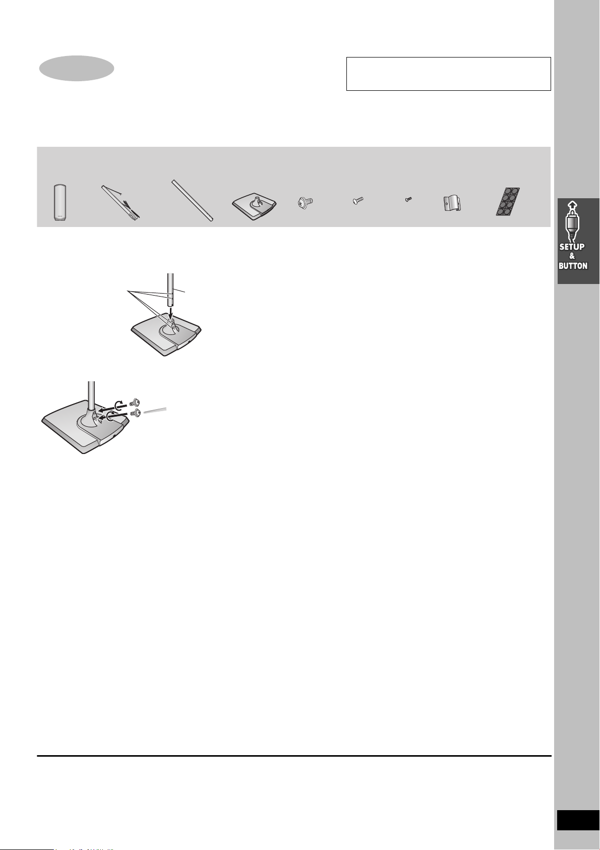
STEP1 Front speaker assembly
Preparation
≥To prevent damage or scratches, lay down a soft cloth and perform assembly on it.
≥For assembly, use a Phillips-head screwdriver.
≥Make sure you have all the indicated components before starting assembly, setup, and connection.
≥There is no difference between the right and left speakers and pipes.
attachment to Panasonic SB-FS730 front speakers.
Use only as indicated in this setup.
2kFront
speakers
2kPipe A
(with a cable)
4kPipes 4kWasher
2kPipe B
1 Attach pipes B to the bases.
A Insert pipe B.
Match these holes when
you insert the pipe.
B Secure pipe B to the base.
Ensure the screws are securely fastened.
Pipe B
Base
2kBases
screws
4kBracket
screws
2kSmall
screws
2kBrackets 8k
pads
Rubber
3 Attach pipes A to the speakers.
Slot the screw head in between the 2 stoppers of the speaker
groove.
Align the screw head with the speaker groove.
Ensure the pipe is fastened on straight by gradually tightening the right
and left screws alternately until fully tightened.
To prevent short-circuit, do not cover the connection terminals
with the pipe.
2 Assemble the pipes.
A Thread the speaker cable from Pipe A through Pipe B
and the base.
For quicker threading, loosely fold the cable in half (do not
crease), pass the folded portion through the pipe, and then
pull the rest of the cable through the base.
B Join Pipe A to Pipe B.
C Secure the pipes.
Ensure the screw is securely fastened.
4 Connect the speaker cables.
5 Secure the speaker cable to the base.
[Note]
You can use the front speakers without assembling with the stands. In this case, attach the included
rubber pads to the base of the speakers. This prevents vibration from causing the speakers to move or
fall over. Use 4 pads per speaker.
RQT7921
5
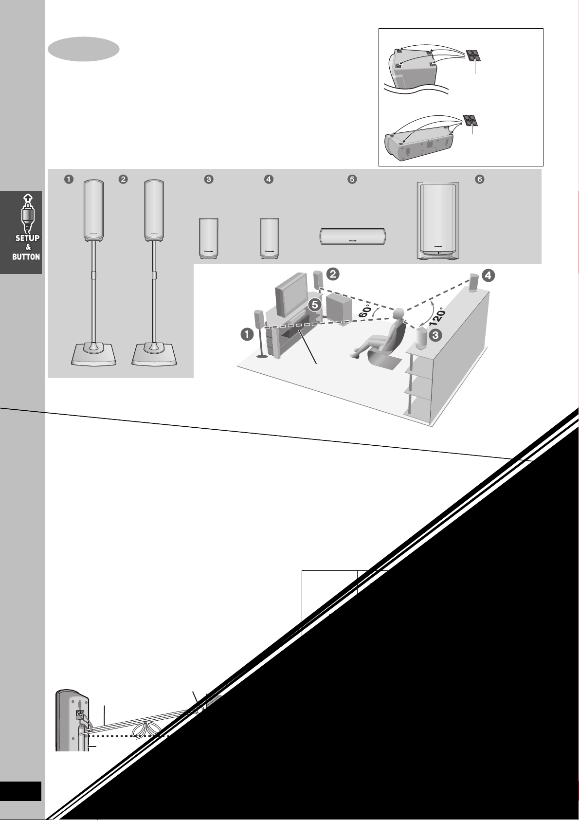
STEP2 Positioning
Bottom of surround speaker
How you set up your speakers can affect the bass and the sound field. Note the following points.
≥Attach the included rubber pads to the base of the center and surround speakers. This
prevents vibration from causing the speakers to move or fall over. Use 4 pads per
speaker.
≥Place speakers on flat secure bases.
≥Placing speakers too close to floors, walls, and corners can result in excessive bass. Cover
walls and windows with thick curtains.
Front
(L)
Front
(R)
(L)
Setup example
Surround
(R)
Center SubwooferSurround
6
Rubber pads
Bottom of center speaker
Rubber pads
RQT7921
6
Place the front, center and surround speakers at approximately
the same distance from the seating position. The angles in the
diagram are approximate.
l See page 43 for other speaker setup options.
≥Use only supplied speakers
Using other speakers can damage the unit and sound quality will be
negatively affected.
≥Set the speakers up on an even surface to prevent them from falling.
Take proper precautions to prevent the speakers from falling if you
cannot set them up on an even surface.
Main unit
Note
Keep your speakers at least 10mm (13/32q) away from the system for
proper ventilation.
Center speaker
≥Vibration caused by the center speaker can disrupt the picture if it is
placed directly on the television. Put the center speaker on a rack or
shelf.
≥To prevent the speakers from falling do not place the speakers
directly on top of the television.
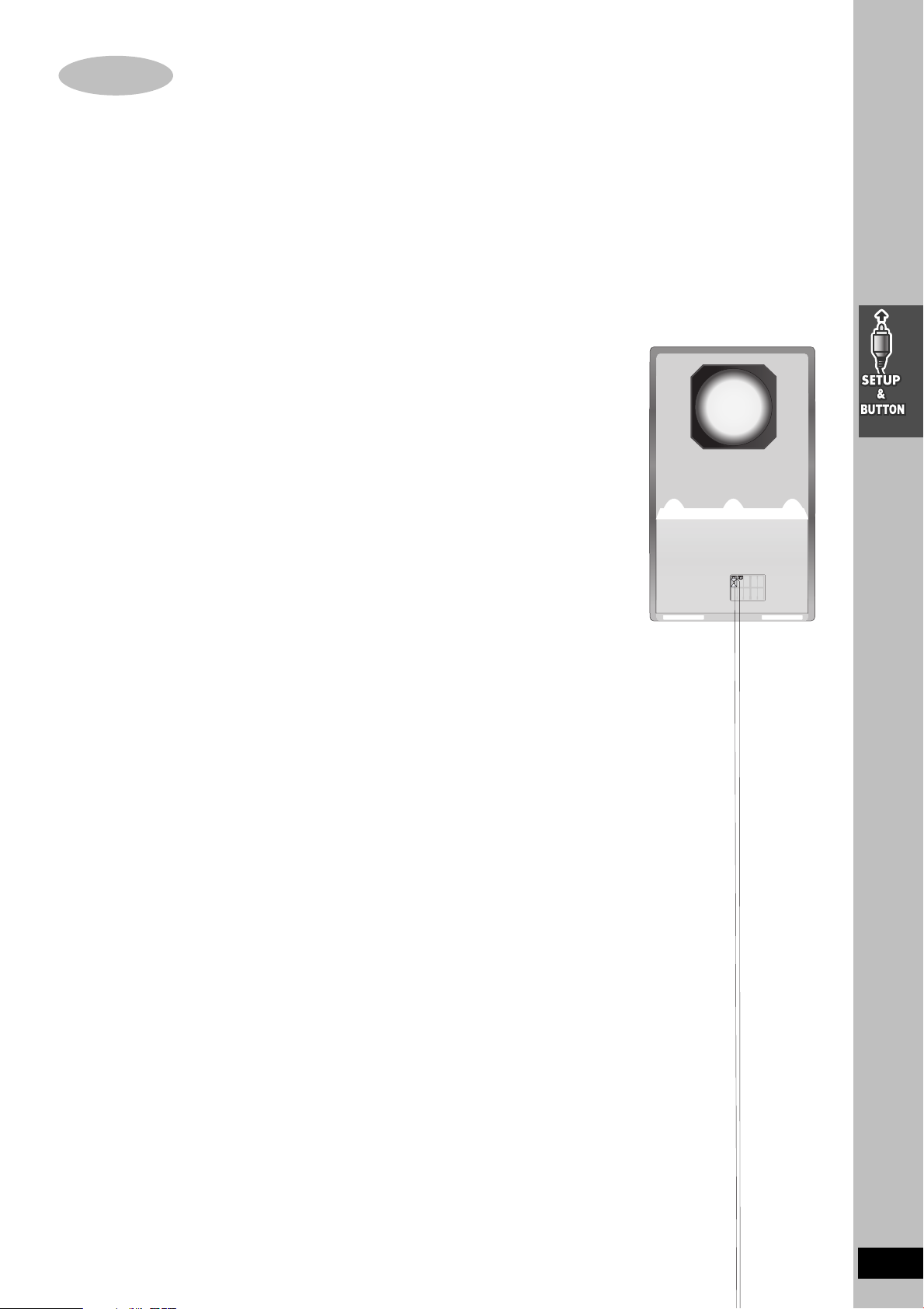
Surround speaker
∫ Preventing the speakers from falling over
Preparation
Attach screw eyes (not included) to secure the speakers to the wall
≥You will need to obtain the appropriate screw eyes to match the walls
or pillars to which they are going to be fastened.
≥Consult a qualified housing contractor concerning the appropriate
procedure when attaching to a concrete wall or a surface that may
not have strong enough support. Improper attachment may result in
damage to the wall or speakers.
String (not included)
Rear of the speaker
1 Thread the string (not included) through the slot on the rear of the
speaker to prevent it from falling over.
2 Loop the string through the screw eye and tie tightly.
Screw eye (not included)
Wall
Approx. 150 mm (5
29
/32z)
Main unit
Subwoofer
Place to the right or left of the television, on the floor or a sturdy shelf
so that it won’t cause vibration.
Leave 10 cm (4q) at the rear for ventilation.
Notes on speaker use
≥You can damage your speakers and shorten their useful life if you
play sound at high levels over extended periods.
≥Reduce the volume in the following cases to avoid damage.
– When playing distorted sound.
– When the speakers are receiving howling from a record player,
noise from FM broadcasts, or continuous signals from an oscillator,
test disc, or electronic instrument.
– When adjusting the sound quality.
– When turning the unit on or off.
Caution
≥The main unit and supplied speakers are
only to be used as indicated in this setup.
Failure to do so may lead to damage to the
amplifier and/or the speakers, and may
result in the risk of fire. Consult a qualified
service person if damage has occurred or if
you experience a sudden change in
performance.
≥Do not attempt to attach these speakers to
walls using methods other than those
described in this manual.
Caution
Do not stand on the base and shake the
speaker.
Be cautious when children are near.

STEP3 Connecting speakers with the subwoofer
≥Attach the speaker-cable stickers to make connection easier.
≥The terminals of the subwoofer have high output power. Carefully connect the speaker wires.
Speaker cables
≥1kshort cable: For center speaker
≥2klong cables: For surround speakers
SUBWOOFER
Insert the wire fully.
Speaker-cable sticker
Click!
2 FRONT (R)
1 FRONT (L)
4 SURROUND (R)
5 CENTER
White
Blue
Sheet of speaker-cable stickers
RQCA 1029
3 SURROUND (L)
[Note]
≥Never short-circuit positive
(i) and negative (j)
speaker wires.
≥Be sure to connect only
positive (White) wires to
positive (i) terminals and
negative (Blue) wires to
negative (j) terminals.
Incorrect connection can
damage the speakers.
STEP4 Video connections
Basic connection
Video cable75 ≠ coaxial cable
Antenna cable (not included)
(usually disconnected from the television)
LOOP
From
Cable TV
Outdoor antenna
Indoor antenna
If the connector doesn’t
match l 44
ANT
GND
FM
75
ANT
AM
LOOP
ANT
EXT
TO
SB-WA830
A
DIGITAL
TRANSMITTER
RF IN
RF OUT
75 ≠ coaxial
cable
(included, l 8)
Connect video cables directly to your
television
The video signals on DVDs and videotapes have
copyright protection. The video may not be shown
correctly if you connect through an A/V selector or
other equipment.
EXT
DVD/VHS
DVD
VIDEO
L
R
IN
S-VIDEO
Y
PB/
C
B
PR/
R
C
COMPONENT
VIDEO OUT
OUT
OUT
Video cable
(included)
AC IN
Main unit
Television
(not included)
VHF/UHF
RF IN
VIDEO
IN
RQT7921
7

STEP
5
Radio and system connection
[Note]
The included AC power supply cords are for use with this unit only. Do
not use them with other equipment.
RQT7921
9
Conserving power
RF IN
RF OU
LOOP
EXT
75
AM
ANT
FM
ANT
LOOP
ANT
GND
The system consumes a small amount of power, even when it is
turned off. The amount of power used depends on the display setting
(l 38):
BRIGHT: 3.7 W DIM: 3.4 W OFF: 1.9 W
To save power when the unit is not to be used for a long time, unplug it
from the household AC outlet.
You will need to reset some memory items after plugging the unit.
Before unplugging the AC power supply cords
1Press [Í] to turn off the unit.
2 After “BYE” on the display disappears, unplug the AC power
supply cords.
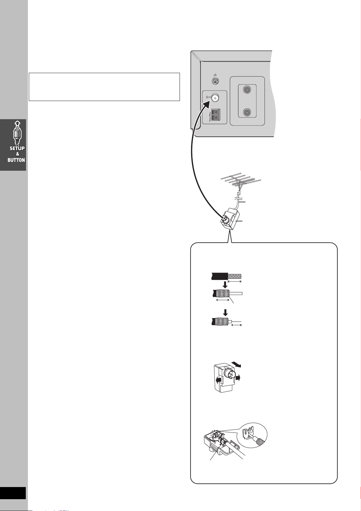
∫ Optional FM antenna connection
Use FM outdoor antenna if radio reception is poor.
≥Disconnect the outdoor antenna when the unit is not in use.
≥Do not use the outdoor antenna during an electrical storm.
FM outdoor antenna
(Using a television antenna)
≥Disconnect the FM indoor antenna.
≥The antenna should be installed by a competent technician.
Rework your outdoor antenna’s 75 ≠ coaxial cable as follows.
75 ≠ coaxial cable
(not included)
Antenna plug
(not included)
For example; Panasonic Antenna plug (K2RC021B0001,
not included)
1 Remove a piece of the outer vinyl insulator.
13
10 mm (
10 mm (
13
/32z)
Peel back
7 mm (
9
/32z)
/32z)
2 Carefully pull the tabs apart to remove the cover.
2
RQT7921
10
1
1
3 Install the coaxial cable.
Clamp the cable conductor, and wind it on so that it does
not contact anything else.
Clamp with pliers
4 Attach the cover.
\
After plugging the unit into your household AC outlet and pressing [Í]
to turn the unit on for the first time, the unit automatically tunes in all
the channels it can receive and sets the clock.
The unit determines the type of transmission, TV or CATV, as follows:
TV: when there are less than 5 CATV channels.
CATV: when there are 5 or more CATV channels.
Preparation
≥Confirm that the antenna is connected correctly.
≥Turn on the television and select the video input for the VHS.
≥Press [VHS] to put the remote control in VHS mode.
Press [Í] to turn on the unit.
Plug-in Auto Tuning starts and the unit puts the stations it can receive
into channels (l 37, Channel range).
∫ Batteries
Do not:
≥mix old and new batteries.
≥use different types at the same time.
≥heat or expose to flame.
≥take apart or short circuit.
≥attempt to recharge alkaline or manganese batteries.
≥use batteries if the covering has been peeled off.
Mishandling of batteries can cause electrolyte leakage which can
damage items the fluid contacts and may cause a fire.
Remove if the remote control is not going to be used for a long period
of time. Store in a cool, dark place.
∫ Use
Aim at the sensor (l 14), avoiding obstacles at a maximum range of 7
m (23 feet) directly in front of the unit.
The unit starts auto clock setting when finished, then displays the time.
[Note]
If auto tuning stops partway (by changing the source, turning the unit
off, or due to a power failure).
1 Disconnect the AC power supply cord on the main unit and then
reconnect it.
2 Turn on the main unit.
To cancel partway
Press [MENU].
∫To start Plug-in Auto Tuning again (after relocation, for
example)
Preparation
≥Press [Í] to turn on the unit.
≥Make sure there is no video cassette tape loaded in the unit.
≥Press [DVD/VHS] to select “VHS” as the source.
1 Press and hold [W CH] and [X CH] on the main unit simultaneously
for 3 seconds until the channel changes to “2”.
2 Disconnect the AC power supply cord on the main unit and then
reconnect it.
3 Turn on the main unit. Plug-in Auto Tuning restarts.
∫To set the channels manually (l 37).
∫If the unit couldn’t set the clock automatically
The MANUAL CLOCK SET screen appears. Set the time manually
(l 36).
RQT7921
11

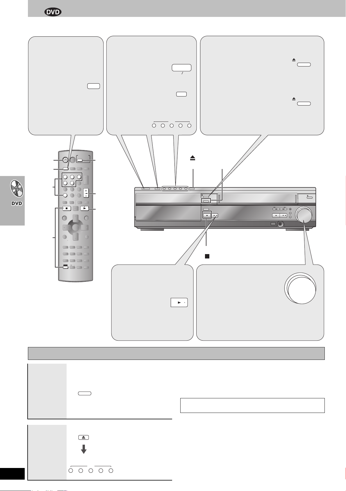
Control reference guide
≥See reference pages in brackets.
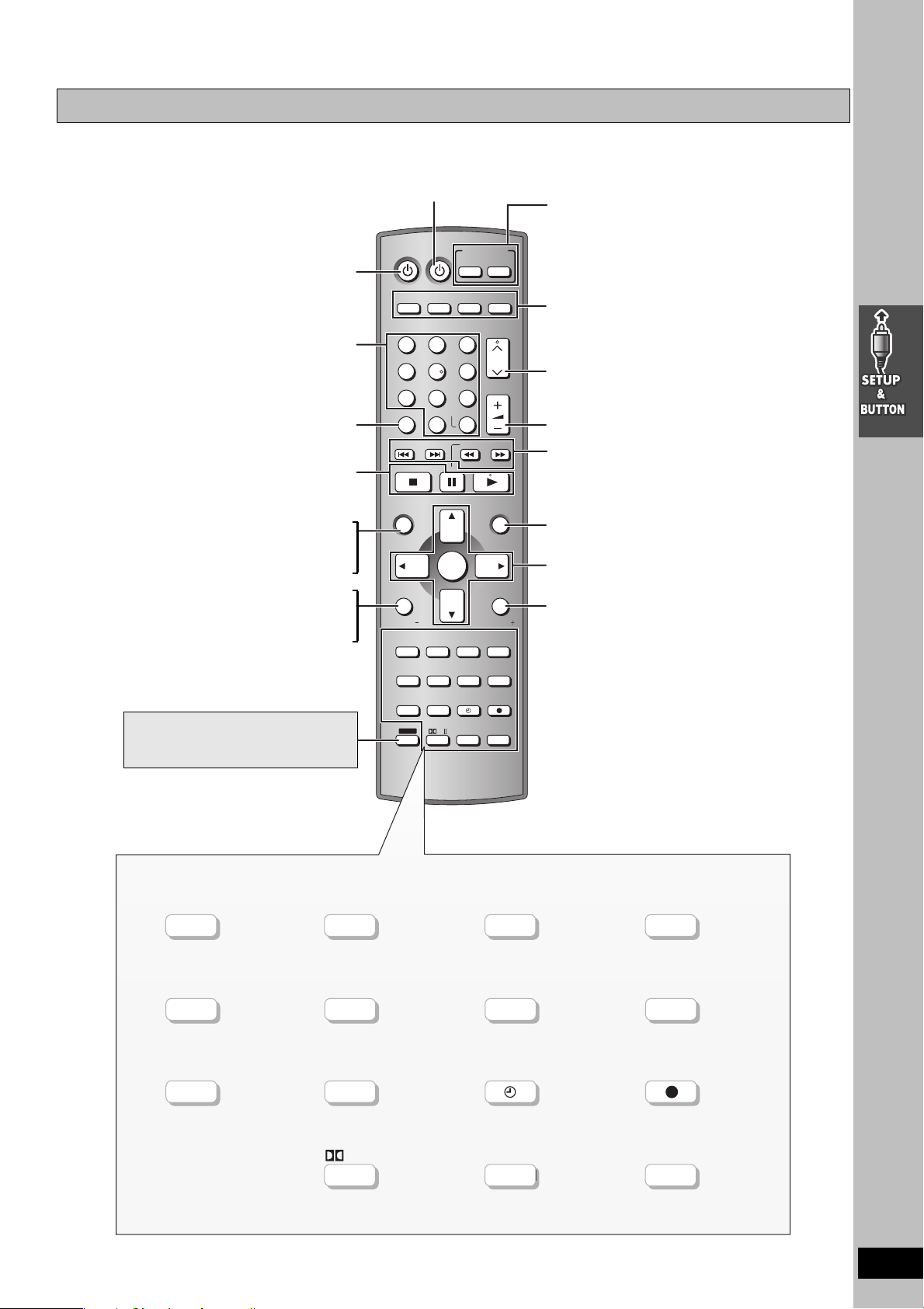
Remote control
TV Power button (12)
INPUT SELECTOR
TV
FM/AMDVD/VHS
Top menu button (22)
Direct navigator button (23)
Jet navigator button (34)
Status button (35)
Function button (24)
TV volume down button (12)
To use functions labelled in orange
While pressing [SHIFT], press the
corresponding button
DVD TV
VHS
123
4
5
PICTURE MODE
78
SETUP
DISC
0
SKIP
OPEN/CLOSE/EJECT
TOP MENU
NAVI
DIRECT
NAVIGATOR
ENTER
STATUS/
FUNCTIONS
TV VOL
MULTI RE-MASTER
MIX 2CH
QUICK OSD
ZOOM
H.BASS
C.FOCUS
SUBWOOFER LEVEL
SFC
ADVANCE
CM SKIP
DISC REVIEW
SPEEDPROG
SLEEP
SHIFT
PL
6
9
ENTER
S10
SLOW/SEARCH
JET REW
PROGRESSIVE
CD MODE
TEST
SUPER SRND
QUICK
REPLAY
AUDIO
CANCEL
TUNER
CH
VOLUM E
MENU
PLAY
LIST
RETURN
TV VOL
REPEAT
PLAY MODE
CH SELECT
MUTING
REC
RESET
TV/VIDEO
RQT7921
13
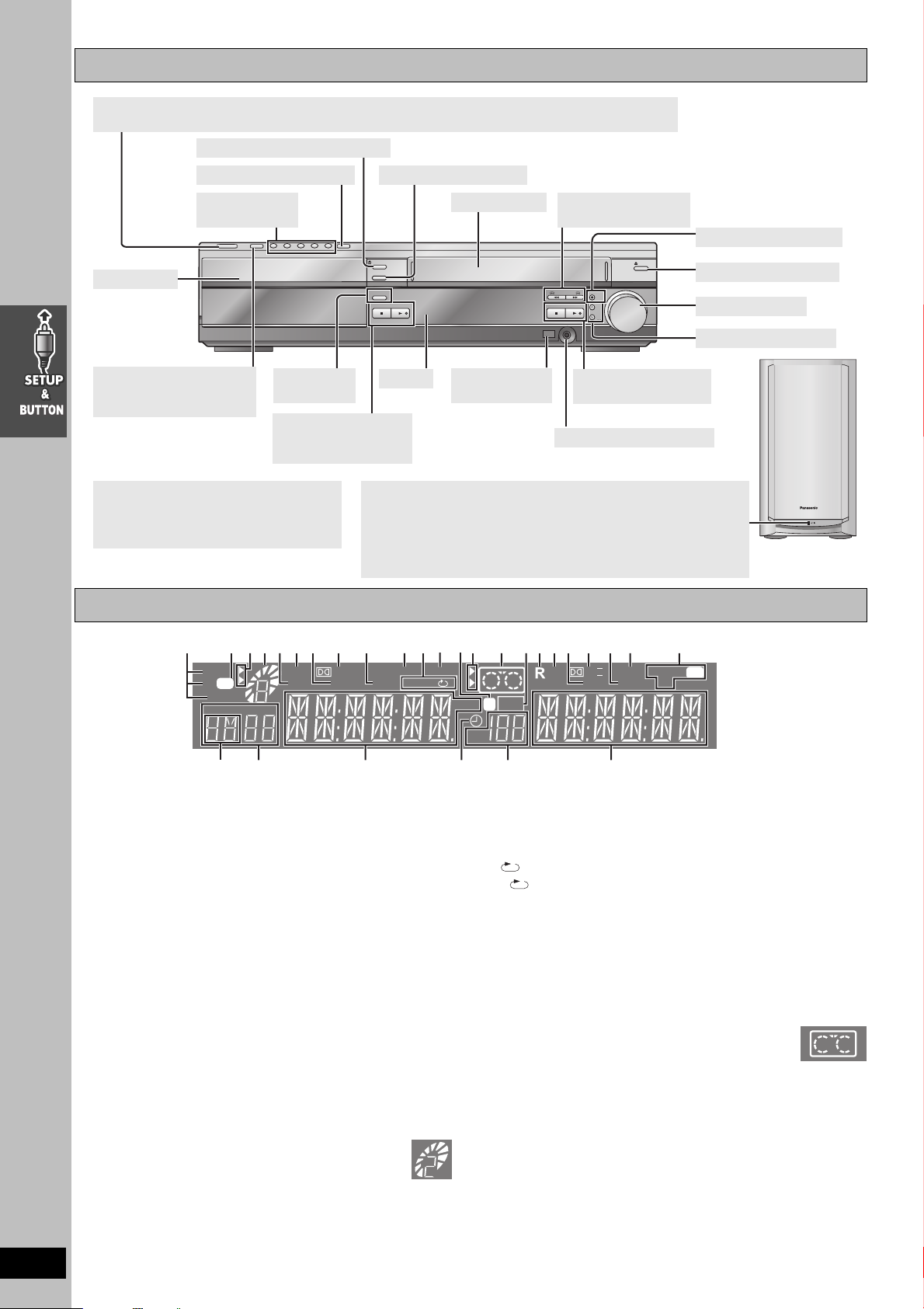
Main unit and subwoofer
Power button [Í/I POWER] l 11; Press to switch the unit from on to standby mode or vice versa.
In standby mode, the unit is still consuming a small amount of power.
Drawer open/close button l 16
Disc change button l 16
Disc buttons
[DISC1–5] l 16
Drawer l 16
Input selector button
VHS>DVD/CD>FM>AM
H. Bass
button l 42
^"""""""""""""n
DVD stop button l 16
DVD play button l 16
Demo button l 9
[Note]
≥“BYE” is displayed when the unit turns off.
Remove the power plug after this display
disappears.
Main unit display
Disc check button l 16
Tape slot l 28 Fast-forward and
rewind buttons l 28
Recording button l 30
OPEN/CLOSE
DISC CHECK
H.BASS
STOP
-
DEMO
/REW FF/
PLAY
STOP PLAY
PHONES
EJECT
VOLUME
REC
CH
DOWN UP
Tape eject button l 28
Volume dial l 16
Channel buttons l 11
Display
Remote control
signal sensor
VHS stop button l 28
VHS play button l 28
Headphone terminal l 42
AC supply indicator [AC IN]
≥This indicator lights when the subwoofer is connected to the
household AC outlet and through the system cable to the main unit.
≥When main unit is turned on, this indicator will light on or vice versa.
≥The indicator light turns off in approximately 10 seconds after the
unit is disconnected from the AC outlet.
RQT7921
14
2 1[1]
MONO
ST
CD
TUNED
CT PG
PL
TG
[2] 7
:
PGM
DTS
DIGITAL
PROG.
D.MIX
RND
AB
H.BASS
HDCD
ALLALL
∫Common display
[1] Program indicator. . . . . . . . . . . . . . . . . . . . . . . . . . . . . . . 20, 40
[2] H. Bass indicator . . . . . . . . . . . . . . . . . . . . . . . . . . . . . . . . . . 42
[3] Wireless Theater indicator. . . . . . . . . . . . . . . . . . . . . . . . . . . . 9
≥Indicates when you use the Digital Transmitter and Receiver.
[4] Center Focus indicator. . . . . . . . . . . . . . . . . . . . . . . . . . . . . . 41
[5] Sound Field Control indicator . . . . . . . . . . . . . . . . . . . . . . . . 41
[6] Dolby Pro Logic II indicator . . . . . . . . . . . . . . . . . . . . . . . . . 41
[7] Super Surround indicator . . . . . . . . . . . . . . . . . . . . . . . . . . . 41
[8] SLEEP timer indicator . . . . . . . . . . . . . . . . . . . . . . . . . . . . . . 42
[9] Main display (Orange)
Disc play elapsed time, program recording start time, volume,
TUNER frequency/channel display, various messages, etc.
[10]
Main display (White)
Time display, video play/record elapsed time, program recording
end time, various messages, etc.
∫DVD operation
1 CD mode indicator . . . . . . . . . . . . . . . . . . . . . . . . . . . . . . . . . 18
Lights when CD mode is on.
2 DVD selector indicator
Lights when DVD is selected.
3 Operation status of DVD section
≥Displays play status graphically.
Rotating: playing
Stopped: paused
Blinking: Standby to resume play (l 17, Stop)
≥Numeric indicator lights corresponding to disc tray number.
4 DTS indicator
5 Progressive video indicator. . . . . . . . . . . . . . . . . . . . . . . . . . 17
6 Dolby Digital indicator
[7]
[8]4 5 7 [5][3]
[6]4[2] [4]328 9 5 3 [1] 6 1
dB
C.F
PL II
SFC
REC
w
SLEEP
S.SRND
SPLPEP
VP
CH
6[9]
7 Down mix indicator. . . . . . . . . . . . . . . . . . . . . . . . . . . . . . . . . 42
8 HDCD indicator . . . . . . . . . . . . . . . . . . . . . . . . . . . . . . . . . . . . 15
9 Play sequence indicator
CD mode indicator + RND: During all disc random play. . . . . 21
RND: During random play. . . . . . . . . . . . . . . . . . . . . . . . . . . . . 21
: During repeat . . . . . . . . . . . . . . . . . . . . . . . . . . . . . . . . . . 19
AB: During A-B repeat . . . . . . . . . . . . . . . . . . . . . . . . . . . . 25
: Title/Group/Playlist/Chapter/Track/Program display
[10]
∫VHS operation
1 VHS selector indicator
Lights when the selector is in VHS mode.
2 Operation status of VHS section
≥Lights when a video cassette is inserted.
≥Blinks when recording or timer recording is attempted with no
video cassette inserted.
≥Displays play status graphically.
Rotating: playing
Stopped: paused
3 Recording indicator . . . . . . . . . . . . . . . . . . . . . . . . . . . . . . . . 30
4 Repeat playback indicator . . . . . . . . . . . . . . . . . . . . . . . . . . . 29
5 Tape speed indicator . . . . . . . . . . . . . . . . . . . . . . . . . . . . . . . 30
6 Timer program recording indicator. . . . . . . . . . . . . . . . . . . . 32
7 Channel display
∫Tuner operation
[1] Radio broadcast display . . . . . . . . . . . . . . . . . . . . . . . . . . . . 40
MONO: Forced monaural
ST: Stereo
TUNED: Receiving radio signal
[2] Band display
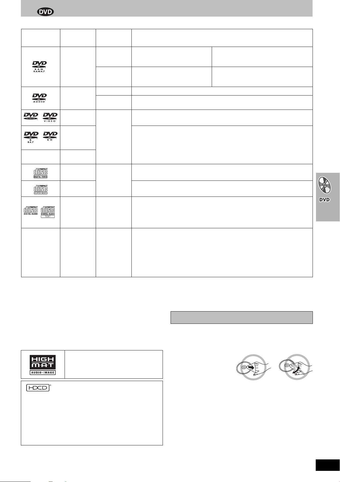
Discs that can be played
Logo Disc
DVD-RAM
DVD-Audio
DVD-Video
DVD-R
(DVD-Video)/
DVD-RW
(DVD-Video)
—
iR (Video)/
iRW (Video)
Video CD
SVCD Conforming to IEC62107
Indication in
operating
instructions
[RAM]
[JPEG]
[DVD-A] —
[DVD-V]
[DVD-V]
[VCD]
Remarks
Recorded using Version 1.1 of the
Video Recording Format (a unified
video recording standard).
Recorded using the DCF (Design
rule for Camera File system)
standard Ver 1.0.
≥Recorded with DVD video recorders, DVD
video cameras, personal computers, etc.
≥
Remove discs from their cartridges before use.
≥
Recorded with Panasonic DVD-Video recorders.
≥To play JPEG files, select “Play as Data
Disc” in Other Menu (l 25).
Some DVD-Audio discs contain DVD-Video content.
To play DVD-Video content, select “Play as DVD-Video” in Other Menu (l 25).
—
Discs recorded and finalized
§
on DVD video recorders or DVD video cameras.
—
This unit is compatible with HDCD, but does not support the Peak Extend function.
(A function which expands the dynamic range of high level signals)
CD [CD]
HDCD-encoded CDs sound better because they are encoded with 20 bits, as
compared with 16 bits for all other CDs.
≥During HDCD play, “HDCD” lights on the unit’s display.
≥This unit can play CD-R/RW (audio recording disc) recorded with the formats on the
[WMA]
—
CD-R
CD-RW
[MP3]
[JPEG]
[CD]
[VCD]
left. Close the sessions or finalize
≥HighMAT
TM
discs
WMA, MP3 or JPEG files only.
To play without using the HighMAT
Menu (l 25).
≥[WMA] This unit is not compatible with Multiple Bit Rate (MBR: a file that contains the
§
the disc after recording.
TM
function, select “Play as Data Disc” in Other
same content encoded at several different bit rates).
§
A process that allows play on compatible equipment.
≥It may not be possible to play the above discs in all cases due to the type of disc or condition of the recording.
Note about using a DualDisc
The digital audio content side of a DualDisc does not meet the technical specifications of the Compact Disc Digital Audio (CD-DA) format so play
may not be possible.
∫Discs that cannot be played
PAL discs (except DVD-Audio), DVD-ROM, CD-ROM, CDV, CD-G,
SACD, Divx Video Discs and Photo CD, DVD-RAM that cannot be
removed from their cartridge, 2.6-GB and 5.2-GB DVD-RAM, and
“Chaoji VCD” available on the market including CVD, DVCD and
SVCD that do not conform to IEC62107.
HighMAT and the HighMAT logo are either
trademarks or registered trademarks of
Microsoft Corporation in the United States
and/or other countries.
Disc handling
∫To prevent damage
Do not;
≥load more than one disc per tray.
≥close the drawer by hand.
∫To clean discs
Wipe with a damp cloth and
then wipe dry.
®
, HDCD
, High Definition Compatible Digital® and
Pacific Microsonics™ are either registered trademarks or
trademarks of Pacific Microsonics, Inc. in the United States and/or
other countries.
HDCD system manufactured under license from Pacific
Microsonics, Inc. This product is covered by one or more of the
following: In the USA : 5,479,168, 5,638,074, 5,640,161,
5,808,574, 5,838,274, 5,854,600, 5,864,311, 5,872,531, and in
Australia: 669114, with other patents pending.
∫Handling precautions
≥Do not attach labels or stickers to discs (This may cause disc
warping, rendering it unusable).
≥Do not write on the label side with a ball-point pen or other writing
instrument.
≥Do not use record cleaning sprays, benzine, thinner, static electricity
prevention liquids or any other solvent.
≥Do not use scratch-proof protectors or covers.
≥Do not use the following discs:
– Discs with exposed adhesive from removed stickers or labels
(rented discs etc).
– Discs that are badly warped or cracked.
– Irregularly shaped discs, such as heart shapes.
RQT7921
15
Basic play
Turn on the television and select the appropriate video input for the DVD.
1 Put the remote
control in DVD
mode.
DVD
VHS
INPUT SELECTOR
TV
5
ENTER
0
ENTER
MIX 2CH
ZOOM
C.FOCUS
SFC
ADVANCE
DISC REVIEW
SPEEDPROG
SLEEP
PL
6
9
S10
SLOW/SEARCH
JET REW
PROGRESSIVE
CD MODE
TEST
SUPER SRND
QUICK
REPLAY
AUDIO
CANCEL
FM/AMDVD/VHS
TUNER
CH
VOLUME
MENU
PLAY
LIST
RETURN
TV VOL
REPEAT
PLAY MODE
CH SELECT
MUTING
REC
RESET
TV/VIDEO
2
1
4
5,6
DVD TV
123
4
PICTURE MODE
78
SETUP
DISC
SKIP
OPEN/CLOSE/EJECT
TOP MENU
NAVI
DIRECT
NAVIGATOR
STATUS/
FUNCTIONS
TV VOL
MULTI RE-MASTER
QUICK OSD
H.BASS
SUBWOOFER LEVEL
CM SKIP
SHIFT
2 Turn on the unit.
3 Select “DVD/CD”.
4 Select the disc tray.
3
3
8
7
1
2 3 4 5
POWER
Í
I
INPUT SELECTOR
DISC
DISC CHANGE
5 Open the disc tray
and load the disc.
≥Load double-sided discs so the label for the
side you want to play is facing up.
6 Close the disc tray.
≥To load discs on the other trays,
repeat steps 4–6.
DISC CHECK
OPEN/CLOSE
DISC CHECK
H.BASS
STOP
-
DEMO
STOP
PLAY
STOP PLAY
/REW FF/
PHONES
OPEN/CLOSE
OPEN/CLOSE
EJECT
VOLUME
REC
CH
DOWN UP
VOLUME
RQT7921
16
Using main unit
Checking
the disc
trays
Changing
the discs
during play
1
DISC CHECK
DISC CHANGE
DISC
2 3 4 5
7 Start play.
≥Press [∫] to stop play.
All trays except the tray in
play open without interrupting
play. While stopped, all trays
will open.
≥Press [DISC CHECK] again
to close the trays.
≥Do not pull out the trays,
remove or insert discs
during the disc check.
You can change the other
discs without interrupting
play.
≥After selecting the disc tray,
press [< DISC CHANGE] to
close the tray.
8 Adjust the volume.
––dB
N
PLAY
(Minimum)
Volume may be lower when playing
DVD-Video than when playing other discs or during
television broadcasts. Reduce the volume before playing
other sources or returning to the television so volume
doesn’t increase suddenly.
[Note]
≥When “Press PLAY to resume play” is displayed, this position is
memorized even after turning off the unit, changing the source.
(Power off resume)
≥Total title number may not be displayed properly on iR/iRW.
If you are experiencing problems, refer to troubleshooting (l 45–
47).
0dB
(Maximum)
DOWN UP
 Loading...