

Panasonic SC-HT730, SC-HT930, SC-HT933, SC-HT733 User Manual

Dear customer
The lightning flash with arrowhead symbol, within
an equilateral triangle, is intended to alert the user
to the presence of uninsulated “dangerous voltage”
within the product’s enclosure that may be of sufficient magnitude to constitute a risk of electric shock
to persons.
CAUTION
CAUTION: TO REDUCE THE RISK OF ELECTRIC
SHOCK, DO NOT REMOVE SCREWS.
NO USER-SERVICEABLE PARTS
INSIDE.
REFER SERVICING TO QUALIFIED
SERVICE PERSONNEL.
The exclamation point within an equilateral triangle
is intended to alert the user to the presence of
important operating and maintenance (servicing)
instructions in the literature accompanying the appliance.
RISK OF ELECTRIC SHOCK
DO NOT OPEN
Thank you for purchasing this product. For optimum performance
and safety, please read these instructions carefully.
[HT730]: indicates features applicable to SC-HT730 only.
[HT733]: SC-HT733 only.
[HT930]: SC-HT930 only.
[HT933]: SC-HT933 only.
System SC-HT730 SC-HT733 SC-HT930 SC-HT933
Main unit SA-HT730 SA-HT733 SA-HT930 SA-HT933
Front speakers SB-FS730 SB-FS730 SB-FS930 SB-PF920
Center speaker SB-PC730 SB-PC730 SB-PC930 SB-PC920
Surround speakers SB-FS731 SB-FS731 SB-FS931 SB-PS920
Active subwoofer SB-WA730 SB-WA733 SB-WA930 SB-WA933
CAUTION!
THIS PRODUCT UTILIZES A LASER.
USE OF CONTROLS OR ADJUSTMENTS OR
PERFORMANCE OF PROCEDURES OTHER THAN THOSE
SPECIFIED HEREIN MAY RESULT IN HAZARDOUS
RADIATION EXPOSURE.
DO NOT OPEN COVERS AND DO NOT REPAIR YOURSELF.
REFER SERVICING TO QUALIFIED PERSONNEL.
WARNING:
TO REDUCE THE RISK OF FIRE, ELECTRIC SHOCK
OR PRODUCT DAMAGE, DO NOT EXPOSE THIS
APPARATUS TO RAIN, MOISTURE, DRIPPING OR
SPLASHING AND THAT NO OBJECTS FILLED WITH
LIQUIDS, SUCH AS VASES, SHALL BE PLACED ON
THE APPARATUS.
CAUTION!
≥DO NOT INSTALL OR PLACE THIS UNIT IN A BOOKCASE,
BUILT-IN CABINET OR IN ANOTHER CONFINED SPACE.
ENSURE THE UNIT IS WELL VENTILATED. TO PREVENT
RISK OF ELECTRIC SHOCK OR FIRE HAZARD DUE TO
OVERHEATING, ENSURE THAT CURTAINS AND ANY
OTHER MATERIALS DO NOT OBSTRUCT THE
VENTILATION VENTS.
≥DO NOT OBSTRUCT THE UNIT’S VENTILATION OPENINGS
WITH NEWSPAPERS, TABLECLOTHS, CURTAINS, AND
SIMILAR ITEMS.
≥DO NOT PLACE SOURCES OF NAKED FLAMES, SUCH AS
LIGHTED CANDLES, ON THE UNIT.
≥DISPOSE OF BATTERIES IN AN ENVIRONMENTALLY
FRIENDLY MANNER.
≥These operating instructions are applicable to models
SC-HT730, SC-HT733, SC-HT930 and SC-HT933 for a
variety of regions.
≥
Unless otherwise indicated, illustrations in these operating
instructions are of SC-HT730 for U.S.A. and Canada.
≥Operations in these instructions are described mainly
with the remote control, but you can perform the
operations on the main unit if the controls are the same.
THE FOLLOWING APPLIES ONLY IN THE U.S.A.
FCC Note:
This equipment has been tested and found to comply with the limits
for a Class B digital device, pursuant to Part 15 of the FCC Rules.
These limits are designed to provide reasonable protection
against harmful interference in a residential installation. This
equipment generates, uses and can radiate radio frequency
energy and, if not installed and used in accordance with the
instructions, may cause harmful interference to radio
communications. However, there is no guarantee that
interference will not occur in a particular installation. If this
equipment does cause harmful interference to radio or television
reception, which can be determined by turning the equipment off
and on, the user is encouraged to try to correct the interference
by one or more of the following measures:
≥Reorient or relocate the receiving antenna.
≥Increase the separation between the equipment and receiver.
≥Connect the equipment into an outlet on a circuit different from
that to which the receiver is connected.
≥
Consult the dealer or an experienced radio/TV technician for help.
Any unauthorized changes or modifications to this equipment
would void the user’s authority to operate this device.
This device complies with Part 15 of the FCC Rules. Operation is
subject to the following two conditions: (1) This device may not
cause harmful interference, and (2) this device must accept any
interference received, including interference that may cause
undesired operation.
Responsible Party:
Panasonic Corporation of North America
One Panasonic Way
Secaucus, NJ 07094
Telephone No.: 1-800-211-7262
THE FOLLOWING APPLIES ONLY IN THE U.S.A. AND CANADA
This product may receive radio interference caused by mobile
telephones during use. If such interference is apparent, please
increase separation between the product and the mobile
telephone.
The socket outlet shall be installed near the equipment and
easily accessible or the mains plug or an appliance coupler shall
remain readily operable.
For units with PX printed on the outer packaging
THIS UNIT IS INTENDED FOR USE IN MODERATE CLIMATES.
For units with PX printed on the outer packaging
CAUTION:
The AC voltage is different according to the area.
Be sure to set the proper voltage in your area before use.
(For details, please refer to page 12.)
RQT7972
2

TABLE OF CONTENTS
Getting started
IMPORTANT SAFETY INSTRUCTIONS . . . . . . . . . . . . . . .3
Simple setup
STEP 1
STEP 2
STEP 3
STEP 4
STEP 5
STEP 6
STEP 7
Control reference guide. . . . . . . . . . . . . . . . . . . . . . . 14
Discs that can be played . . . . . . . . . . . . . . . . . . . . . . . . .15
Main unit and disc caution. . . . . . . . . . . . . . . . . . . . . . . .15
Front speaker assembly . . . . . . . . . . . . . . . . 4
Other speaker setup options . . . . . . . . . . . . . . . . . . .8
Positioning . . . . . . . . . . . . . . . . . . . . . . . . . . . 9
Connecting speakers with the subwoofer
. . 10
Video connections. . . . . . . . . . . . . . . . . . . . 11
Radio and system connections . . . . . . . . . 12
The remote control . . . . . . . . . . . . . . . . . . . 13
QUICK SETUP . . . . . . . . . . . . . . . . . . . . . . . 13
Disc operations
Basic play . . . . . . . . . . . . . . . . . . . . . . . . . . . . . . . . . . 16
Using the main unit . . . . . . . . . . . . . . . . . . . . . . . . . . . . . . .16
Using the remote control. . . . . . . . . . . . . . . . . . . . . . . . . . . 17
Convenient functions. . . . . . . . . . . . . . . . . . . . . . . . . . . .18
Disc information. . . . . . . . . . . . . . . . . . . . . . . . . . . . . . . . . . . . 18
Displaying current playback condition (QUICK OSD) . . . . . . . 18
Reviewing titles to play (ADVANCED DISC REVIEW). . . . . . . 18
CD sequential play (CD MODE) . . . . . . . . . . . . . . . . . . . . . . . 18
Quick replay. . . . . . . . . . . . . . . . . . . . . . . . . . . . . . . . . . . . . . . 18
Skipping one minute forward (CM SKIP) . . . . . . . . . . . . . . . . . 18
Changing the zoom ratio . . . . . . . . . . . . . . . . . . . . . . . . . . . . . 19
Changing play speed . . . . . . . . . . . . . . . . . . . . . . . . . . . . . . . . 19
Angle selection and Still picture rotation/advance . . . . . . . . . . 19
Changing soundtracks . . . . . . . . . . . . . . . . . . . . . . . . . . . . . . . 19
Changing subtitles . . . . . . . . . . . . . . . . . . . . . . . . . . . . . . . . . . 19
Repeat play . . . . . . . . . . . . . . . . . . . . . . . . . . . . . . . . . . . . . . . 19
Program/Random play. . . . . . . . . . . . . . . . . . . . . . . . . . . . . . . 20
Using navigation menus . . . . . . . . . . . . . . . . . . . . . . . . 22
Playing data discs. . . . . . . . . . . . . . . . . . . . . . . . . . . . . . . . . . . 22
Playing from the selected track in the CD. . . . . . . . . . . . . . . . . 22
Playing HighMAT
Playing RAM discs . . . . . . . . . . . . . . . . . . . . . . . . . . . . . . . . . . 23
TM
discs . . . . . . . . . . . . . . . . . . . . . . . . . . . . . 23
Using on-screen menus . . . . . . . . . . . . . . . . . . . . . . . . . 24
Main menu . . . . . . . . . . . . . . . . . . . . . . . . . . . . . . . . . . . . . . . . 24
Other Settings. . . . . . . . . . . . . . . . . . . . . . . . . . . . . . . . . . . . . . 24
Changing the player settings. . . . . . . . . . . . . . . . . . . . . 26
Changing the delay time (Speaker Settings) . . . . . . . . . . . . . . 27
Other operations
The radio . . . . . . . . . . . . . . . . . . . . . . . . . . . . . . . . . . . . . 28
Automatic presetting. . . . . . . . . . . . . . . . . . . . . . . . . . . . . . . . . 28
Selecting the preset channels . . . . . . . . . . . . . . . . . . . . . . . . . 28
Manual tuning. . . . . . . . . . . . . . . . . . . . . . . . . . . . . . . . . . . . . . 28
Optional antenna connections . . . . . . . . . . . . . . . . . . . . . . . . . 29
Sound field and sound quality. . . . . . . . . . . . . . . . . . . . 30
Sound Field Control . . . . . . . . . . . . . . . . . . . . . . . . . . . . . . . . . 30
Super Surround . . . . . . . . . . . . . . . . . . . . . . . . . . . . . . . . . . . . 30
Center Focus . . . . . . . . . . . . . . . . . . . . . . . . . . . . . . . . . . . . . . 30
Dolby Pro Logic II . . . . . . . . . . . . . . . . . . . . . . . . . . . . . . . . . . . 30
Down-mixing. . . . . . . . . . . . . . . . . . . . . . . . . . . . . . . . . . . . . . . 30
Enhancing the bass sound . . . . . . . . . . . . . . . . . . . . . . . . . . . . 30
Subwoofer level . . . . . . . . . . . . . . . . . . . . . . . . . . . . . . . . . . . . 31
Speaker level adjustments . . . . . . . . . . . . . . . . . . . . . . . . . . . . 31
Other useful functions . . . . . . . . . . . . . . . . . . . . . . . . . . 31
Sleep timer . . . . . . . . . . . . . . . . . . . . . . . . . . . . . . . . . . . . . . . . 31
Muting. . . . . . . . . . . . . . . . . . . . . . . . . . . . . . . . . . . . . . . . . . . . 31
Using headphones . . . . . . . . . . . . . . . . . . . . . . . . . . . . . . . . . . 31
Operating other equipment . . . . . . . . . . . . . . . . . . . . . . 32
Operating the television and the video cassette recorder. . . . . 32
Operating the tape deck ([HT930] [HT933] only) . . . . . . . . . . . . . 33
Reference
Specifications . . . . . . . . . . . . . . . . . . . . . . . . . . . . . . . . . 33
Troubleshooting guide. . . . . . . . . . . . . . . . . . . . . . . . . . 36
Product Service/Maintenance/Glossary . . . . . . . . . . . . 38
Limited Warranty (ONLY FOR U.S.A.). . . . . . . . . . . . . . 39
Accessories. . . . . . . . . . . . . . . . . . . . . . . . . . . . Back cover
TABLE OF CONTENTS / IMPORTANT SAFETY INSTRUCTIONS
IMPORTANT SAFETY INSTRUCTIONS
Read these operating instructions carefully before using the unit. Follow the safety instructions on the unit and the applicable safety instructions
listed below. Keep these operating instructions handy for future reference.
1) Read these instructions.
2) Keep these instructions.
3) Heed all warnings.
4) Follow all instructions.
5) Do not use this apparatus near water.
6) Clean only with dry cloth.
7) Do not block any ventilation openings. Install in accordance with
the manufacturer’s instructions.
8) Do not install near any heat sources such as radiators, heat
registers, stoves, or other apparatus (including amplifiers) that
produce heat.
9) \U.S.A.\ and\Canada]
Do not defeat the safety purpose of the polarized or groundingtype plug. A polarized plug has two blades with one wider than
the other. A grounding-type plug has two blades and a third
grounding prong. The wide blade or the third prong are
provided for your safety. If the provided plug does not fit into
your outlet, consult an electrician for replacement of the
obsolete outlet.
10) Protect the power cord from being walked on or pinched
particularly at plugs, convenience receptacles, and the point
where they exit from the apparatus.
11) Only use attachments/accessories specified by the
manufacturer.
12) Use only with the cart, stand, tripod, bracket, or
table specified by the manufacturer, or sold with
the apparatus. When a cart is used, use caution
when moving the cart/apparatus combination to
avoid injury from tip-over.
13) Unplug this apparatus during lightning storms or
when unused for long periods of time.
14) Refer all servicing to qualified service personnel. Servicing is
required when the apparatus has been damaged in any way,
such as power-supply cord or plug is damaged, liquid has been
spilled or objects have fallen into the apparatus, the apparatus
has been exposed to rain or moisture, does not operate
normally, or has been dropped.
RQT7972
3
Simple setup
The supplied stands are specially designed for
STEP
Preparation
≥To prevent damage or scratches, lay down a soft cloth and perform assembly on it.
≥For assembly, use a Phillips-head screwdriver.
≥Make sure you have all the indicated components before starting assembly, setup, and connection.
≥There is no difference between the right and left speakers and pipes.
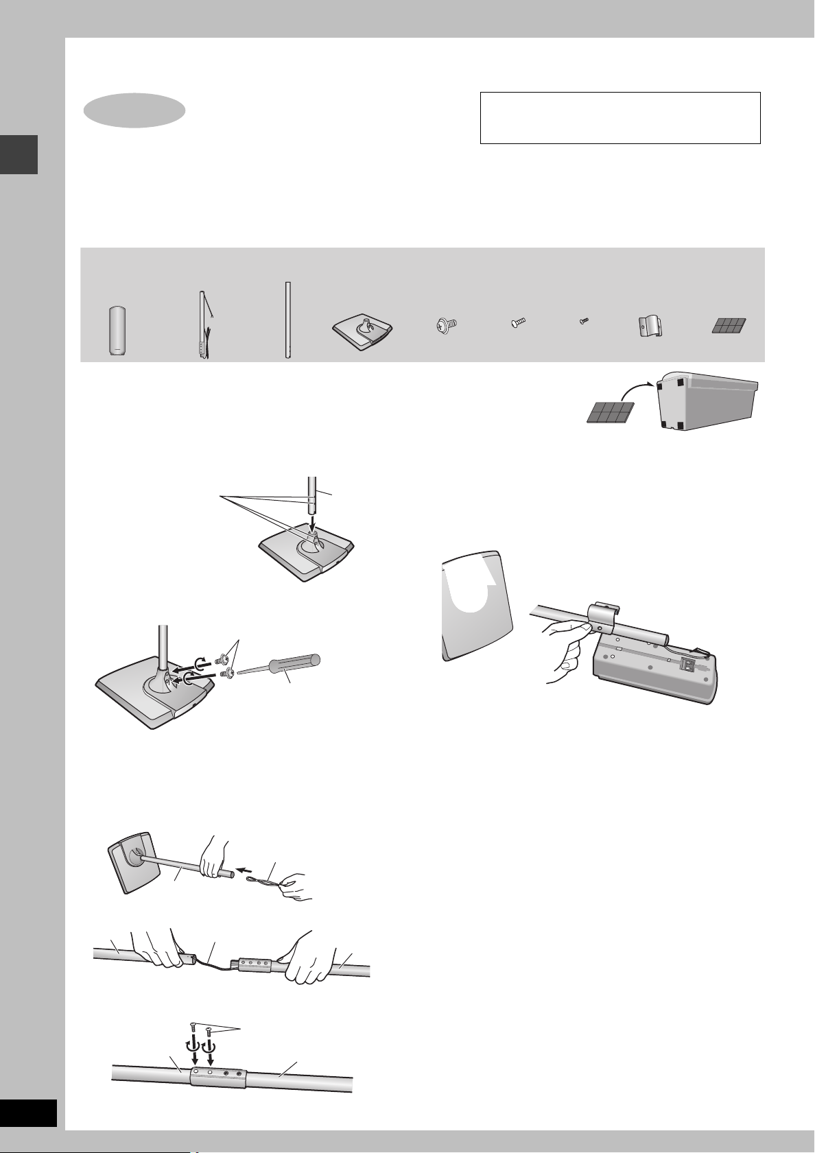
1
Front speaker assembly
[HT730] [HT733]
attachment to Panasonic SB-FS730, SB-FS930 or
SB-PF920 front speakers. Use only as indicated in
this setup.
2 Front
speakers
You can use the front speakers without assembling with the stands. In this case, attach the included
rubber pads to the base of the speakers. This prevents vibration from causing the speakers to move
or fall over. Use 3 or 4 pads per speaker.
4 Pipes 4 Washer
≥2kpipe A
(with cable)
≥2kpipe B
1 Attach the pipes to the bases.
1 Insert pipe B.
Match these holes when you
insert the pipe.
2 Secure pipe B to the base.
Ensure the screws are securely fastened.
Washer screws
2 Bases
Pipe B
Base
screws
4 Bracket
screws
3 Attach the pipes to the speakers.
Slot the screw head in between the 2 stoppers of the speaker
groove.
Ensure the pipe is fastened on straight by gradually tightening the
right and left screws alternately until fully tightened.
To prevent a short-circuit, do not cover the connection
terminals with the pipe.
4 Small
screws
2 Brackets Sheet of
rubber pads
Phillips-head screwdriver
(not included)
2 Assemble the pipes.
1 Thread the speaker cable from pipe A through pipe B and
the base.
For quicker threading, loosely fold the cable in half (do not
crease), pass the folded portion through the pipe, and then pull
the rest of the cable through the base.
Cable
Pipe B
2 Join pipe A to pipe B.
Pipe B
3 Secure the pipes.
Ensure the screws are securely fastened.
Pipe B
Cable
Pipe A
Small screws
Pipe A
4 Connect the speaker cables.
5 Secure the speaker cables to the bases.
RQT7972
4
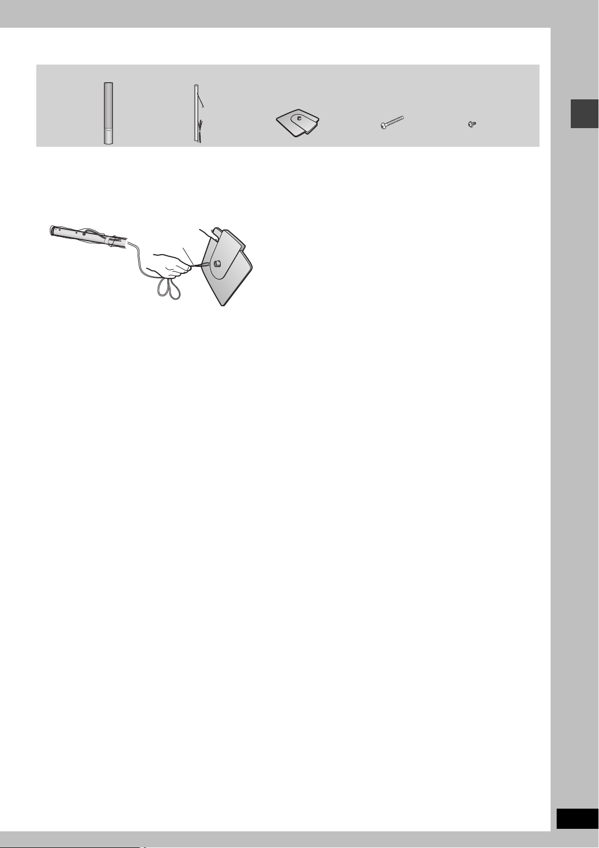
[HT930]
2 Front speakers 2 Bases2 Pipes 4 Short screws4 Long screws
1 Assemble the speaker stands.
1 Thread the speaker cable through the base.
For quicker threading, loosely fold the cable in half (do not
crease), pass the folded portion through the hole, and then pull
the rest of the cable through the base.
2 Insert the pipe.
2 Attach the stands to the speakers.
Ensure the stand is fastened on straight by gradually tightening the
top and bottom screws alternately until fully tightened.
You can also attach to the lower rear of the speaker.
The height of the speaker can be changed when attaching the
stand to the upper rear or lower rear of the speaker.
3 Connect the speaker cables.
3 Secure the pipe to the base.
Ensure the screws are securely fastened.
4 Secure the speaker cables to the bases.
RQT7972
5
Simple setup
STEP1
Front speaker assembly
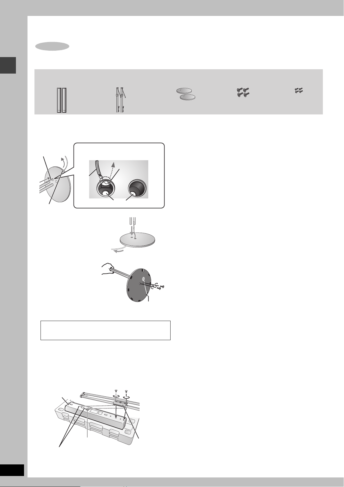
2 Front speakers 2 Bases2 Pipes 4 Small screws4 Large screws
Lessen excess
speaker cable.
Thread the speaker
cable through here.
Cable
Groove
Holes for screws
Insert the pipe while gently
pulling on the speaker cable.
Rear side of base
Cable
Large
screws
[HT933]
1 Attach the pipe to the base.
1 Thread the speaker cable through the base.
2 Insert the pipe.
3
Secure the pipe to the base.
Ensure the screws are
securely fastened by lightly
tightening the left and right
side screws alternately until
fully tightened. (The heads of
the screws protrude slightly
even if you have fully
tightened them.)
∫ Front speaker height
(Assembled diagram)
3 Adjust the speaker height.
≥Check the screws you tightened in procedures 1 and 2 if the pipe
and speaker are loose.
e.g. Attaching the stand to the lower rear
The supplied stands are specially designed for
attachment to Panasonic SB-PF920 front speakers.
Only use as indicated in this setup.
2 Attach the stand to the speakers.
≥
There is no difference between the right and left speakers and stands.
≥Using the polyfoam included with this unit may be convenient.
Ensure the stand is fastened on straight by lightly tightening the top
and bottom screws alternately until fully tightened.
RQT7972
6
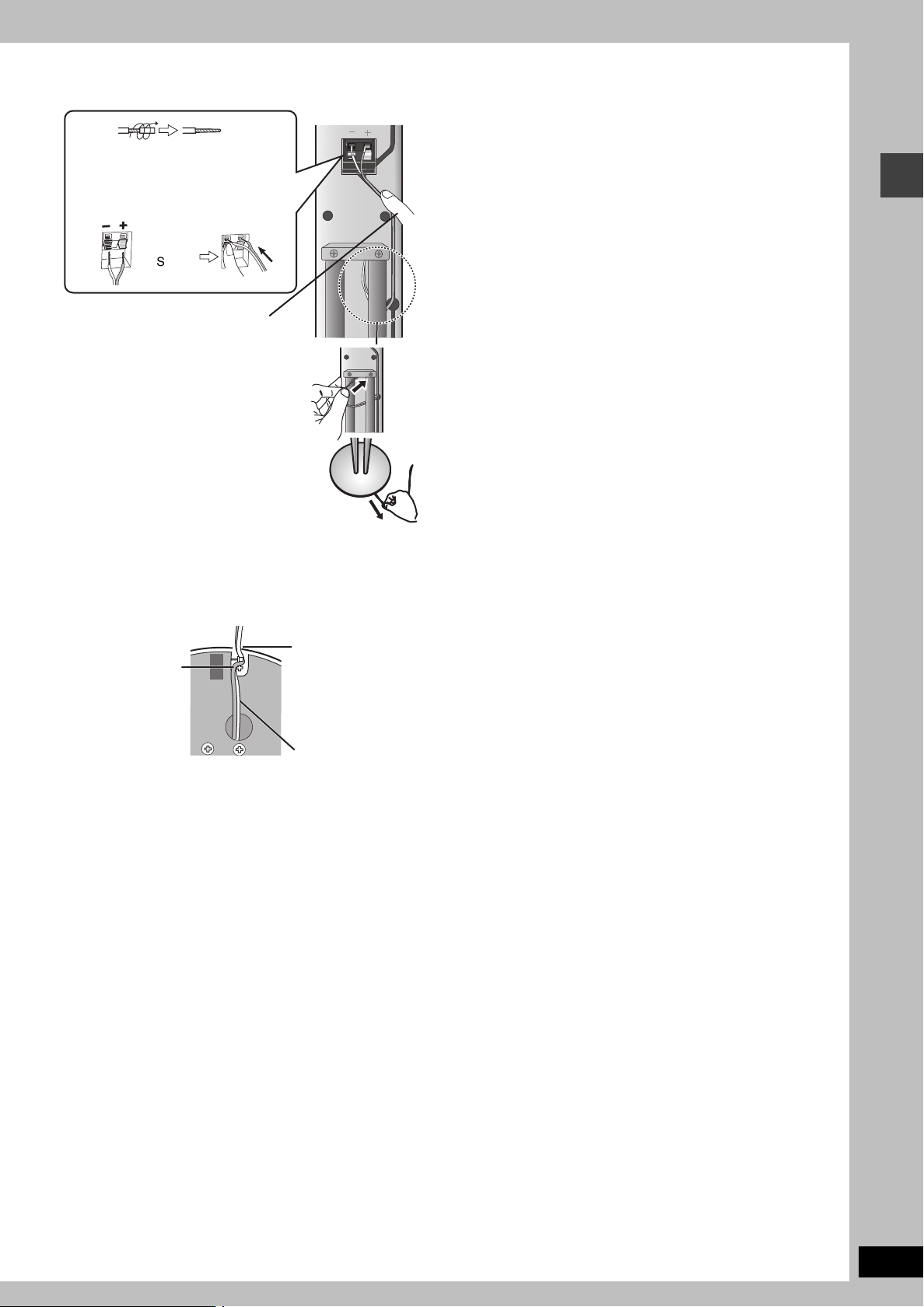
4 Connect the speaker cables.
Rear of the speaker
_: Copper
`:
Silver
Push !
If there is any excess speaker cable, thread
the speaker cable into the opening near the
top of the pipe while pulling the speaker
cable from the bottom of the base.
Press the speaker cable into the
groove.
Twist off the vinyl tips of the speaker
cables.
≥If the speaker cables do not have vinyl
tips, directly connect them to the
terminals.
2 Fit the speaker
cable into the
base cover
groove as far as
possible.
1 Press the speaker
cable and thread
between the
hooks.
Rear side of base
Cable
∫ Preventing the speakers from falling over
Preparation
Attach screw eyes (not included) to secure the speakers to the wall
(➜ diagram below).
≥You will need to obtain the appropriate screw eyes to match the
walls or pillars to which they are going to be fastened.
≥Consult a qualified housing contractor concerning the
appropriate procedure when attaching to a concrete wall or a
surface that may not have strong enough support. Improper
attachment may result in damage to the wall or speakers.
To prevent the speaker from falling over, thread the string (not
included) from the wall to the speaker as shown and tie tightly.
5 Fasten the speaker cable to the base.
≥Using the same polyfoam as in procedure 2 will assist you in
safely and securely fastening the speaker cables.
RQT7972
7
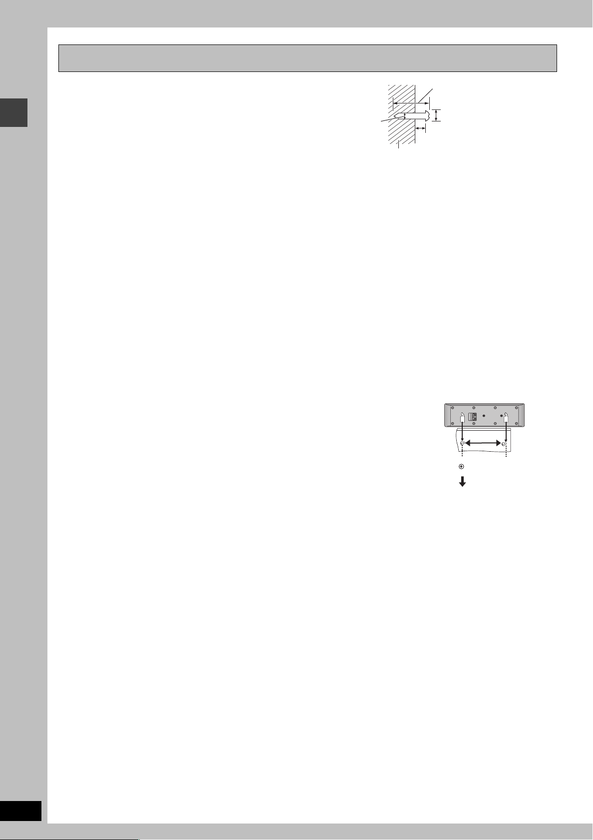
Other speaker setup options
30– 35 mm
(1
3
/16q–13/8q)
‰7.5– 9.4 mm
(
19
/64q–3/8q)
4.0–7.0 mm
(
5
/32q–9/32q)
Wall or pillar
‰3.0– 4.0 mm
(
1
/8q–5/32q)
∫ Attaching to a wall
You can attach all of the speakers to a wall.
1 Drive a screw (not included) into the wall.
2 Fit the speaker securely onto the screw(s) with the hole(s).
≥The wall or pillar on which the speakers are to be attached should be capable of supporting 10 kg (22 lbs) per screw. Consult a qualified
building contractor when attaching the speakers to a wall. Improper attachment may result in damage to the wall and speakers.
≥Use of optional speaker cables is recommended for wall-mounted front speakers. (You can also remove the speaker cables from the pipes
supplied with this system).
≥[HT930] [HT933] When mounting the front speakers to a wall, we recommend using a string (not included) to prevent it from falling (➜ page 7).
Front speaker assembly
RQT7972
8
∫ Fitting speaker stands (not included)
(Except Front speakers)
Ensure the stands meet these conditions before purchasing them.
Note the diameter and length of the screws and the distance between screws as shown in the diagram.
≥The stands must be able to support over 10 kg (22 lbs).
≥The stands must be stable even if the speakers are in a high position.
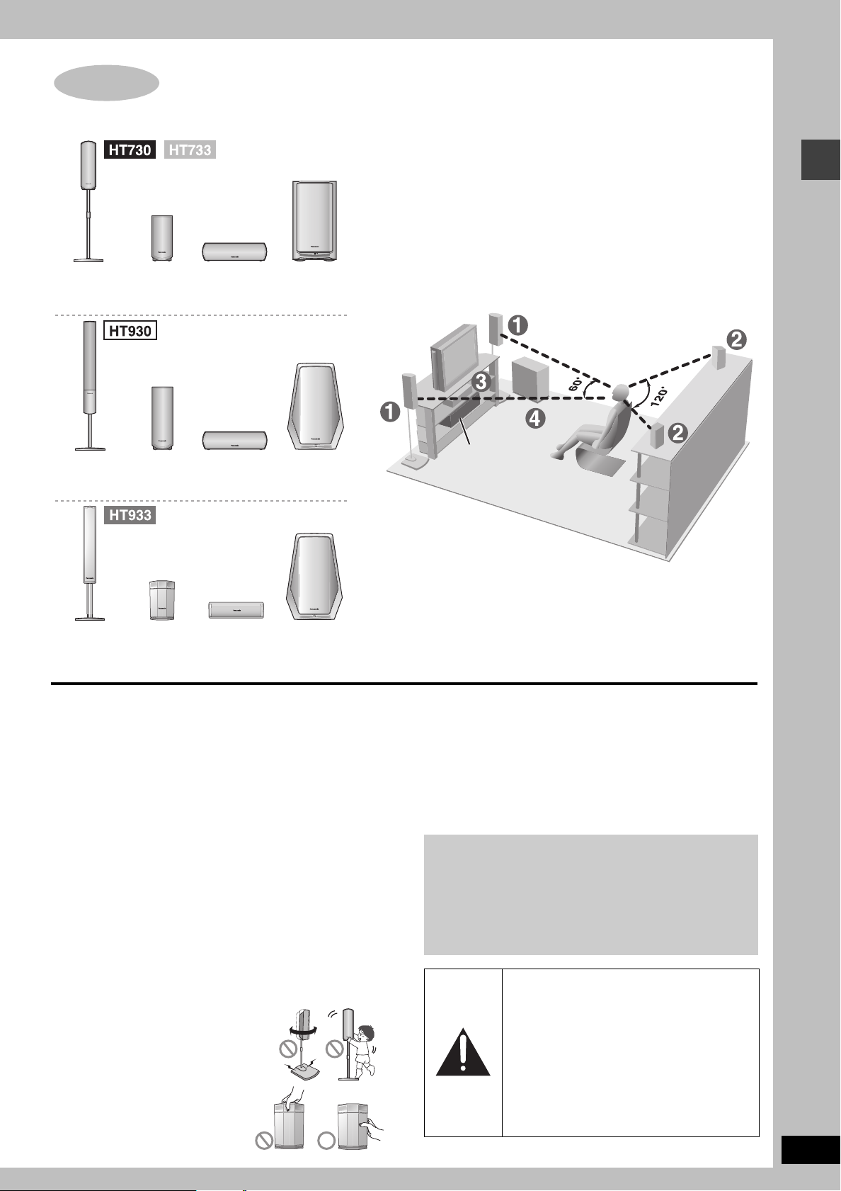
STEP
2
Positioning
How you set up your speakers can affect the bass and the sound field. Note the following points:
≥Place speakers on flat secure bases.
≥Placing speakers too close to floors, walls, and corners can result in excessive bass.
Cover walls and windows with thick curtains.
≥
The left and right speakers are the same with respect to the front and surround speaker pairs.
1
FRONT
(L, R)2SURROUND
(L, R)
4
ACTIVE
SUBWOOFER
4
ACTIVE
SUBWOOFER
1
FRONT
(L, R)
3
CENTER
2
SURROUND
(L, R)
3
CENTER
4
ACTIVE
SUBWOOFER
1
FRONT
(L, R)
3
CENTER
2
SURROUND
(L, R)
Setup example [HT730]
Main unit
≥Place the front, center, and surround speakers at approximately the
same distance from the seating position.
The angles in the diagram are approximate.
e.g. [HT730]
Positioning
≥Use only supplied speakers
≥Set the speakers up on an even surface to prevent them from
Main unit
[Note]
Keep your speakers at least 10 mm (13/32q) away from the system
for proper ventilation.
Center speaker
≥Vibration caused by the center speaker can disrupt the picture if it
≥To prevent the speakers from falling, do not place directly on top
Active subwoofer
Place to the right or left of the television, on the floor or a sturdy
shelf so that it won’t cause vibration. Leave about 30 cm (11
from the television, and 10 cm (4q) at the rear for ventilation.
Caution
≥Do not stand on the base and shake
≥[HT933] Do not touch the netted area of
Using other speakers can damage the unit, and sound quality will
be negatively affected.
falling. Take proper precautions to prevent the speakers from
falling if you cannot set them up on an even surface.
is placed directly on the television. Put the center speaker on a
rack or shelf.
of the television.
the speaker. Be cautious when
children are near.
the surround speakers.
13
/16q)
Notes on speaker use
≥You can damage your speakers and shorten their useful life if you
play sound at high levels over extended periods.
≥Reduce the volume in the following cases to avoid damage:
– When playing distorted sound.
– When the speakers are reverberating due to a record player,
noise from FM broadcasts, or continuous signals from an
oscillator, test disc, or electronic instrument.
– When adjusting the sound quality.
– When turning the unit on or off.
If irregular coloring occurs on your television
The supplied speakers are designed to be used close to a
television, but the picture may be affected with some televisions
and setup combinations.
If this occurs, turn the television off for about 30 minutes.
The television’s demagnetizing function should correct the
problem. If it persists, move the speakers farther away from the
television.
Caution
≥The active subwoofer and supplied
speakers are to be used only as indicated in
this setup. Failure to do so may lead to
damage to the amplifier and/or the
speakers, and may result in the risk of fire.
Consult a qualified service person if
damage has occurred or if you experience a
sudden change in performance.
≥Do not attempt to attach these speakers to
walls using methods other than those
described in this manual.
RQT7972
9
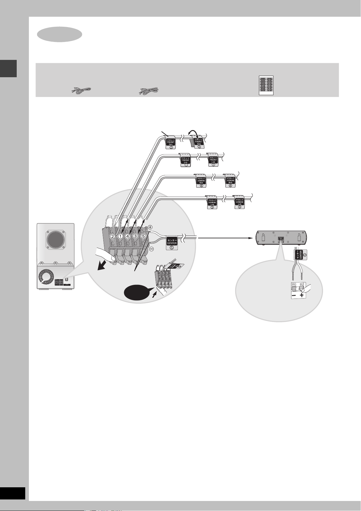
STEP
≥Attach the speaker-cable stickers to make connection easier.
≥The terminals of the subwoofer have high output power. Carefully connect the speaker wires.
3
Connecting speakers with the subwoofer
≥1kshort cable: For center speaker
≥2klong cables: For surround speakers
Speaker-cable sticker
2 FRONT (R)
Connecting speakers with the subwoofer
ACTIVE
SUBWOOFER
Sheet of speaker-cable stickers3 Speaker cables
The illustration shows SC-HT730
for U.S.A. and Canada.
1 FRONT (L)
4 SURROUND (R)
3 SURROUND (L)
5 CENTER
Insert the wire fully.
Click!
[Note]
≥[HT930] [HT933] Even though the subwoofer shown is different, you can connect the speakers to the subwoofer in the same way.
≥Never short-circuit positive (i) and negative (j) speaker wires.
≥Be sure to connect only positive ([HT730] [HT733]: white, [HT930] [HT933]: copper) wires to positive (i) terminals and negative ([HT730] [HT733]:
blue, [HT930] [HT933]: silver) wires to negative (j) terminals. Incorrect connection can damage the speakers.
[HT730] [HT733]
i: White
j: Blue
[HT930] [HT933]
i: Copper
j: Silver
RQT7972
10
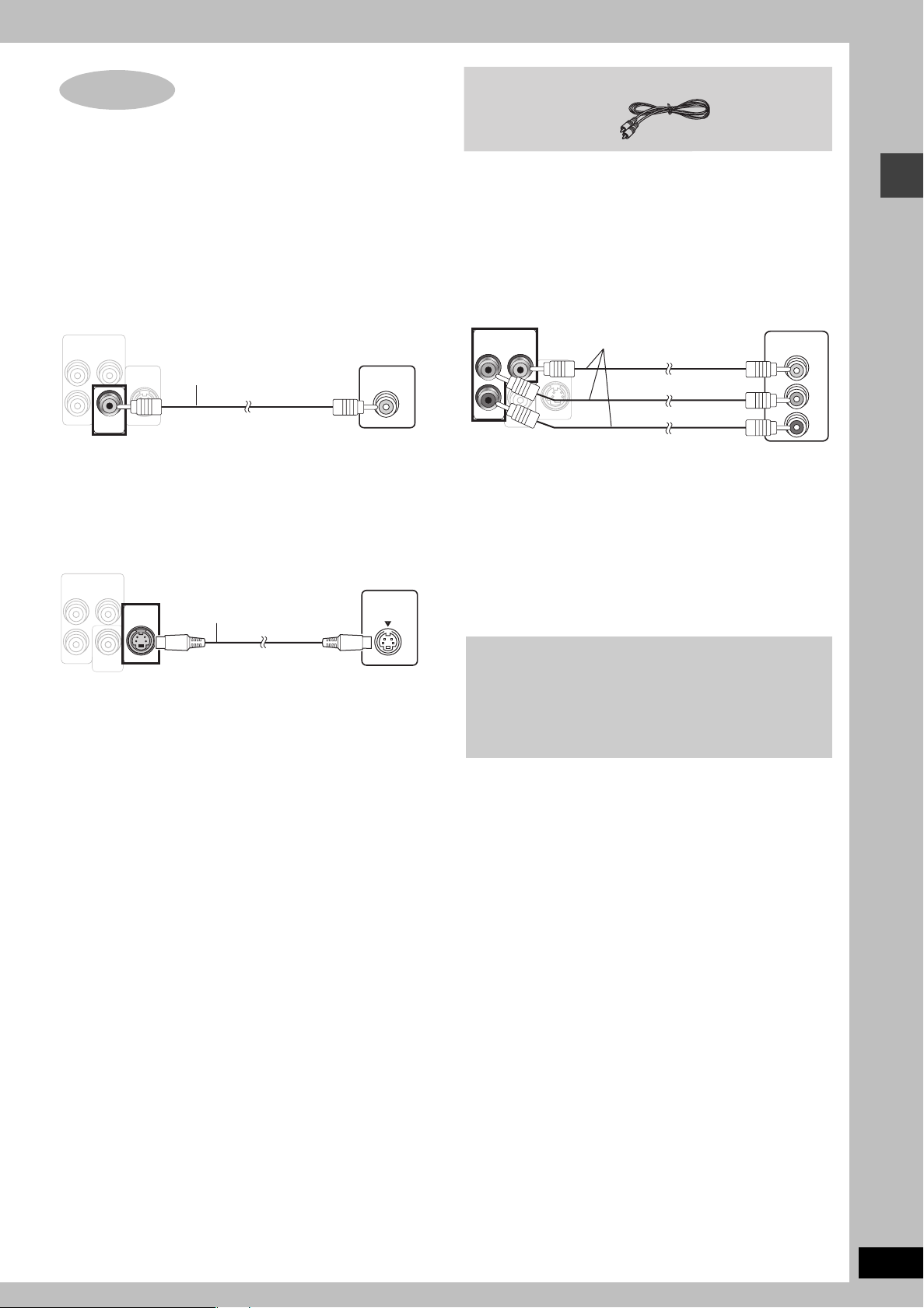
STEP
VID EO
OUT
)
4
Video connections
≥Do not connect through the video cassette recorder.
Due to copy guard protection, the picture may not be displayed properly.
≥Turn the television off before connecting, and refer to the television’s operating instructions.
Video cable
∫ Television with a VIDEO IN terminal
Back of the
main unit
COMPONENT VIDEO OUT
(480p/480i)
P
B
P
R
VIDEO
OUT
Y
S-VIDEO
OUT
Video cable
(included)
Television
(not included)
VIDEO IN
∫ Television with an S-VIDEO IN terminal
Back of the
main unit
COMPONENT VIDEO OUT
(480p/480i)
P
B
P
R
VIDEO
OUT
Y
S-VIDEO
OUT
S-video cable
(not included)
S-VIDEO OUT terminal
The S-VIDEO OUT terminal achieves a more vivid picture than the
VIDEO OUT terminal by separating the chrominance (C) and
luminance (Y) signals. (Actual results depend on the television.)
Television
(not included)
S-VIDEO
IN
∫
Television with COMPONENT VIDEO IN terminals
Back of the
main unit
COMPONENT VIDEO OUT
(480p/480i)
P
B
P
R
VIDEO
OUT
Y
S-VIDEO
OUT
Video cables
(not included)
Television
(not included
COMPONENT
VIDEO IN
Y
PB
PR
COMPONENT VIDEO OUT terminals
These terminals can be used for either interlace or progressive
output and provide a purer picture than the S-VIDEO OUT
terminal. Connection using these terminals outputs the color
difference signals (P
B/PR) and luminance signal (Y) separately in
order to achieve high fidelity in reproducing colors.
≥The description of the component video input terminals depends
on the television or monitor (e.g. Y/P
B/PR, Y/B-Y/R-Y, Y/CB/CR).
Connect to terminals of the same color.
≥After making this connection, select “Darker” from the “Black
Level Control” in the “Video” tab (➜ page 27).
To enjoy progressive video
≥Connect to the component video input terminals on a 480p
compatible television. (Video will not be displayed correctly if
connected to an incompatible television.)
≥All Panasonic televisions that have 480p input connectors are
compatible. Consult the manufacturer if you have another
brand of television.
Video connections
RQT7972
11
STEP
TV
AUDI O
IN
VCR
AUDIO
IN
A
L
FM ANTFM ANT
AM ANTAM ANT
DIGITAL
TRANSMITTER
(7(75≠)
LOOPLOOP
EXTEXT
COMP
P
B
P
R
R
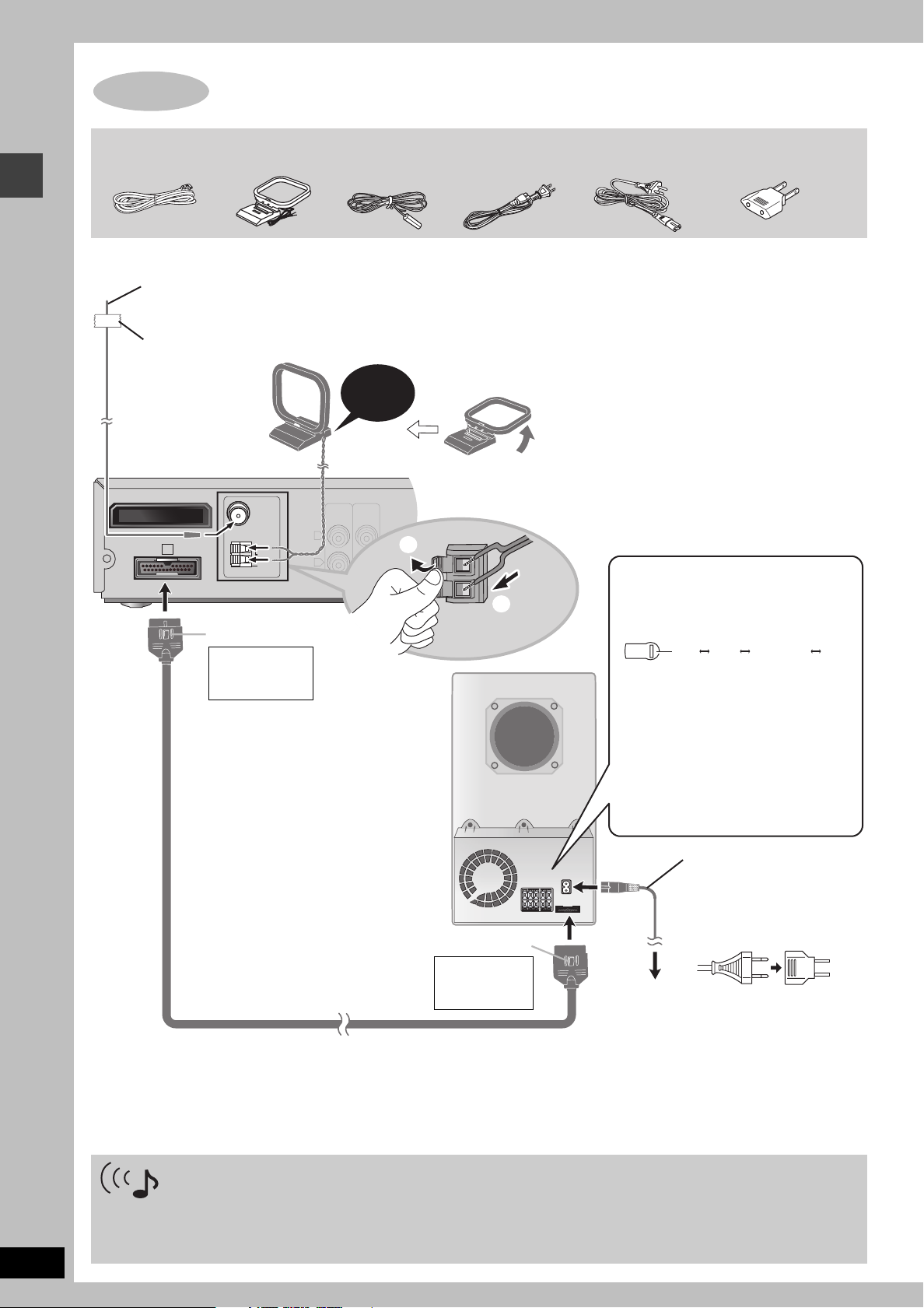
5
Radio and system connections
Radio and system connections
System cable AM loop antenna FM indoor antenna AC power supply cord
\U.S.A.\and\Canada] \Others]
≥Connect the AC power supply cord after all other connections are complete.
≥Optional antenna connections (➜ page 29).
FM indoor antenna
Affix this end of the antenna where
reception is best.
Adhesive tape
Click!
Main unit
1
2
Catch up
To disconnect
Press the catch
and pull out.
Power plug adaptor
\Areas\except\U.S.A.\and\Canada]
The illustration shows SC-HT730
for U.S.A. and Canada.
AM loop antenna
Stand the antenna up on its base.
Place the antenna where reception is best.
Keep loose antenna cable away from other
wires and cables.
[For[areas[except[U.S.A.[and[Canada[
Before connecting the AC
power supply cord
Set the voltage.
127 V 110 V 220 V-230 V 240 V
VOLT ADJ
Use a flat-head screwdriver to turn the
voltage selector on the back of the
subwoofer to the appropriate position for
the area in which this system is used.
If the power supply in your area is 115 V or
120 V, please set the voltage selector as
follows:
≥For 115 V: Set to 110 V.
≥For 120 V: Set to 127 V.
RQT7972
12
AC power supply cord
[For\areas\except\U.S.A.\and\Canada]
≥If the power plug does not fit
Active subwoofer
Catch up
To disconnect
Press the catch
System cable
Conserving power
The main unit consumes a small amount of power, even when it is turned off (For U.S.A. and Canada: approx. 0.5 W or for other areas: approx.
0.9 W). To save power when the unit is not to be used for a long time, unplug it from the household AC outlet.
You will need to reset some memory items after plugging in the unit.
and pull out.
To household
AC outlet
your AC outlet
Use the power plug adaptor
(included).
If it still doesn’t fit, contact an
electrical parts distributor for
assistance.
[Note]
The included AC power supply cord is for use with this unit only. Do not use it with other equipment.
Set your surround sound free!
\For\U.S.A.\and\Canada] (Except SC-HT933)
When you insert the digital transmitter into the DIGITAL TRANSMITTER slot of the main unit and connect the surround speakers to the
receiver, you can enjoy surround speaker sound wirelessly.
For details, please refer to the operating instructions for Panasonic SH-FX50 Digital Transmitter and Receiver.
Panasonic SH-FX50 Digital Transmitter and Receiver (optional)
 Loading...