

Panasonic SC-HT900GN, SC-HT700EB, SC-HT700GN, SC-HT900EB, SC-HT700EE User Manual
...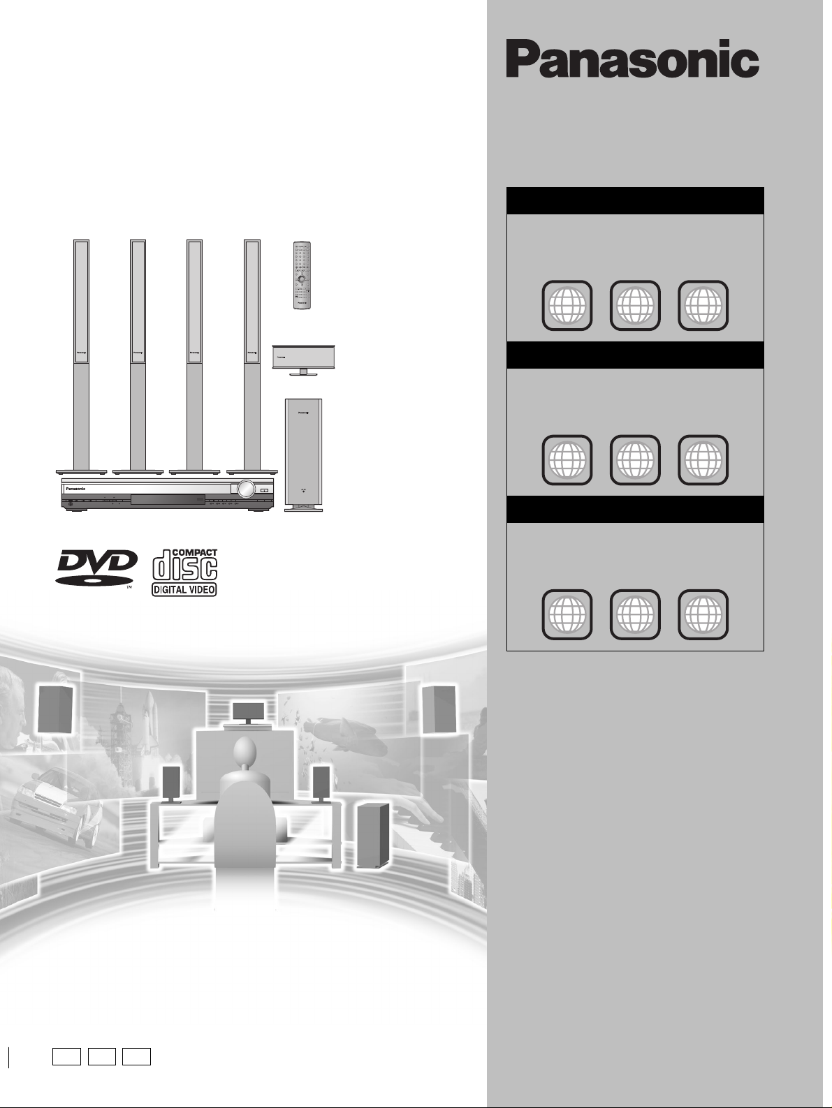
DVD Home Theater Sound System
Operating Instructions
Model No. SC-HT900/SC-HT700
AV SYSTEM
TV VCR
DIGITAL
TV/AV
TUNER/BANDDVD/CD
AUX
DISC
123
DISC 1 DISC 2
DISC 3
PAGE
GROUP
456
DISC 4 DISC 5
SEQUENTIAL
7809
REPEAT
FL DISPLAY
S
10/-/--
PLAY MODE
CANCEL
SKIP
SLOW/SEARCH
CH
TOP MENU
MENU
DIRECT
PLAY LIST
NAVIGATOR
ENTER
DISPLAY
RETURN
TV VOL
s
TV VOL
r
VOLUME
SUBWOOFER
S.POSITION
C.FOCUS
MIX 2CH
LEVEL
SFC
S.SRND
PL
SLEEP
ZOOM
AV AFFECT
SETUP
P.MEMORY
C.S.M
AUDIO
MUTING
TEST
DR COMP
DELAY TIME
SHIFT
SUBTITLE
CH SELECT
QUICK REPLAY
Region number supported by
this player
Region numbers are allocated to DVD players and
software according to where they are sold.
For the United Kingdom
≥The region number of this player is “2”.
≥The player will play DVD-Video marked with
labels containing “2” or “ALL”.
Example:
2
2
ALL
For Australia and N.Z.
≥The region number of this player is “4”.
≥The player will play DVD-Video marked with
labels containing “4” or “ALL”.
Example:
3
5
R
VOLUME
OPEN/CLOSE
DOWN
PROGRESSIVE
SELECTOR
DIGITAL IN
C.S.M
Í/I
PHONES
TUNE MODETUNING FM MODE MEMORY
12345
DISCV.R.S M.R.S
UP
DISC EXCHANGE
DISC SKIP
The illustration shows SC-HT900 for the United Kingdom and Russia.
AUDIO/VIDEO
2
4
ALL
4
6
For Russia
≥The region number of this player is “5”.
≥The player will play DVD-Video marked with
labels containing “5” or “ALL”.
Example:
2
5
ALL
Before connecting, operating or adjusting this
product, please read these instructions completely.
Please keep this manual for future reference.
4
5
EB
EE GN
[Note]
“EB” on the packaging indicates the United
Kingdom.
RQT6756-2B
Dear customer
Thank you for purchasing this product.
For optimum performance and safety, please read these instructions
carefully.
[HT900] : indicates features applicable to SC-HT900 only.
[HT700] : SC-HT700 only.
System SC-HT900 SC-HT700
Main unit SA-HT900 SA-HT700
Front speakers SB-FS900 SB-FS700
Center speaker SB-PC701 SB-PC700
Surround speakers SB-FS900 SB-FS801A
Active subwoofer SB-WA340 SB-WA330
Getting started
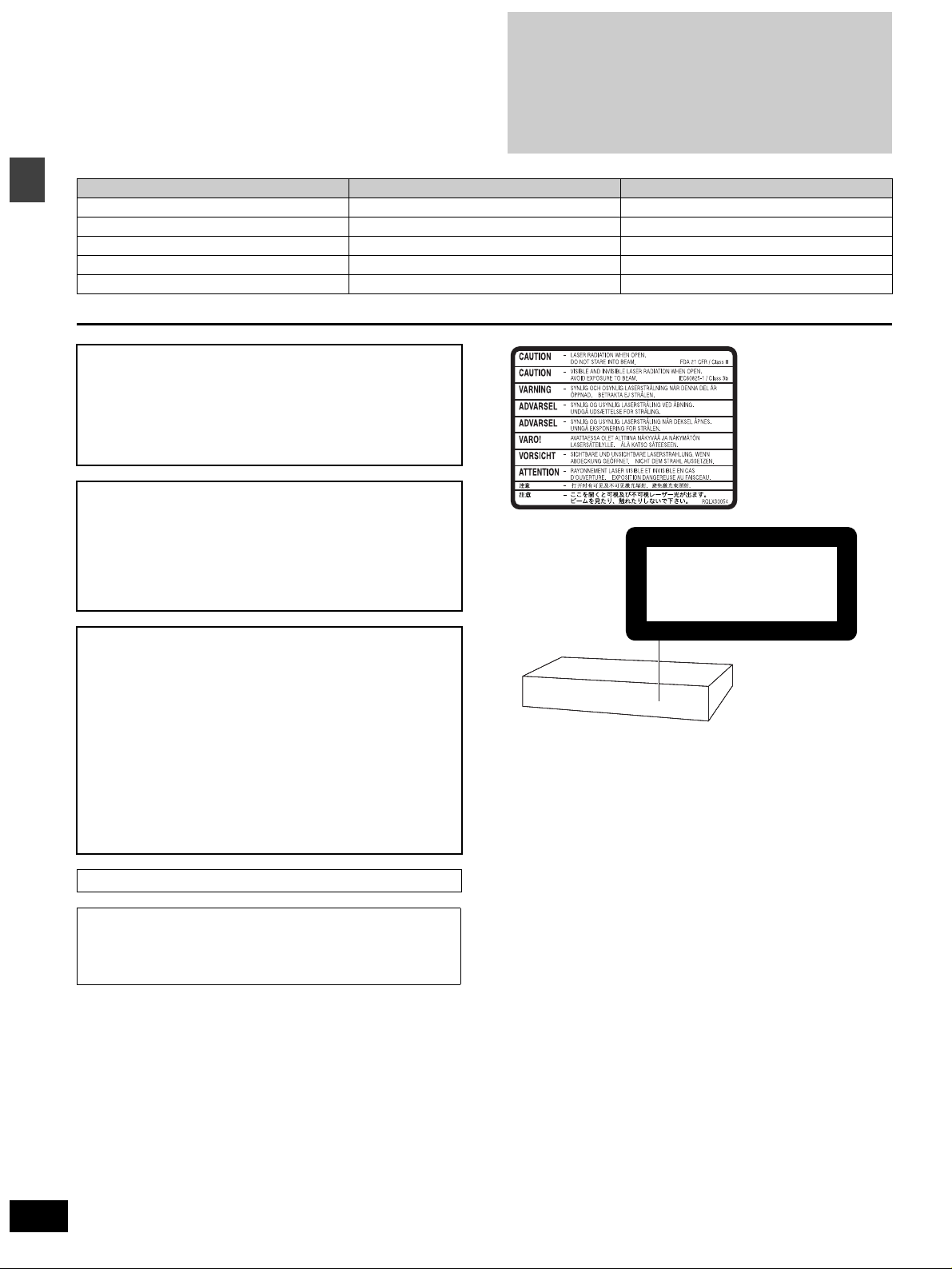
CAUTION!
THIS PRODUCT UTILIZES A LASER.
USE OF CONTROLS OR ADJUSTMENTS OR PERFORMANCE
OF PROCEDURES OTHER THAN THOSE SPECIFIED HEREIN
MAY RESULT IN HAZARDOUS RADIATION EXPOSURE.
DO NOT OPEN COVERS AND DO NOT REPAIR YOURSELF.
REFER SERVICING TO QUALIFIED PERSONNEL.
≥These operating instructions are applicable to models
SC-HT900 and SC-HT700 for a variety regions.
≥Unless otherwise indicated, illustrations in these
operating instructions are of SC-HT900 for the United
Kingdom and Russia.
≥Operations in these instructions are described mainly
with the remote control, but you can do the operations on
the main unit if the controls are the same.
WARNING:
TO REDUCE THE RISK OF FIRE, ELECTRIC SHOCK
OR PRODUCT DAMAGE, DO NOT EXPOSE THIS
APPARATUS TO RAIN, MOISTURE, DRIPPING OR
SPLASHING AND THAT NO OBJECTS FILLED WITH
LIQUIDS, SUCH AS VASES, SHALL BE PLACED ON
THE APPARATUS.
CAUTION!
≥
DO NOT INSTALL OR PLACE THIS UNIT IN A BOOKCASE,
BUILT-IN CABINET OR IN ANOTHER CONFINED SPACE.
ENSURE THE UNIT IS WELL VENTILATED. TO PREVENT
RISK OF ELECTRIC SHOCK OR FIRE HAZARD DUE TO
OVERHEATING, ENSURE THAT CURTAINS AND ANY OTHER
MATERIALS DO NOT OBSTRUCT THE VENTILATION VENTS.
≥DO NOT OBSTRUCT THE UNIT’S VENTILATION OPENINGS
WITH NEWSPAPERS, TABLECLOTHS, CURTAINS, AND
SIMILAR ITEMS.
≥DO NOT PLACE SOURCES OF NAKED FLAMES, SUCH AS
LIGHTED CANDLES, ON THE UNIT.
≥DISPOSE OF BATTERIES IN AN ENVIRONMENTALLY
FRIENDLY MANNER.
THIS UNIT IS INTENDED FOR USE IN MODERATE CLIMATES.
This product may receive radio interference caused by mobile
telephones during use. If such interference is apparent, please
increase separation between the product and the mobile
telephone.
(Inside of product)
CLASS 1
LASER PRODUCT
(Back of product)
RQT6756
2
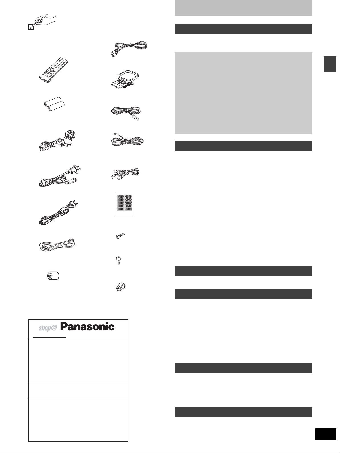
Accessories
Please check and identify the supplied accessories.
Use numbers indicated in parentheses when asking
for replacement parts.
∏ 1 Remote control
[HT900]
(EUR7623X80)
[HT700]
(EUR7623X90)
∏ 2 Batteries
for remote control
∏ 1 AC mains lead
[For\the\United\Kingdom]
(RJA0053-3X)
[For\Australia\and\N.Z.]
(RJA0035-2X)
[For\Russia]
(RJA0019-2X)
∏ 1 System cable
(K1HA25HA0001)
∏ [For\the\United\Kingdom\only]
1 Antenna plug adaptor
(K1YZ02000013)
[Note]
The included AC mains lead is for use with this unit only. Do not use
it with other equipment.
[For\the\United\Kingdom]and\Republic\of\Ireland\
www.panasonic.co.uk (for UK customers only)
≥ Order accessory and consumable items for your
product with ease and confidence by telephoning our
Customer Care Centre Mon–Friday 9:00am–5:30pm.
(Excluding public holidays.)
≥ Or go on line through our Internet Accessory ordering
application.
≥ Most major credit and debit cards accepted.
≥ All enquiries transactions and distribution facilities are
provided directly by Panasonic UK Ltd.
≥ It couldn’t be simpler!
Customer Care Centre
For UK customers: 08705 357357
For Republic of Ireland customers: 01 289 8333
Technical Support
For UK customers: 0870 1 505610
This Technical Support Hot Line number is for
Panasonic PC software related products only.
For Republic of Ireland, please use the Customer Care
Centre number listed above for all enquiries.
For all other product related enquiries, please use the
Customer Care Centre numbers listed above.
∏ 1 Video cable
(RJL1P016B15A)
∏ 1 AM loop antenna
(N1DADYY00002)
∏ 1 FM indoor antenna
[For\the\United\Kingdom]and\Russia]
(RSA0007-J)
[For\Australia\and\N.Z.]
(RSA0006-J)
∏ 5 Speaker cables
(RFA2163-J)
3k4-m cables
2k10-m cables
∏ 1 Sheet of speaker-cable
stickers
[HT900]
∏ 8 Silver screws
(XSN5r16FN)
[HT900]
∏ 4 Black screws
(XTB3r10JFZ)
[HT900]
∏ 4Clips
(QWBG002AA)
Table of contents
Getting started
Accessories. . . . . . . . . . . . . . . . . . . . . . . . . . . . . . . . . . . . 3
Caution for AC Mains Lead . . . . . . . . . . . . . . . . . . . . . . . 4
Disc information . . . . . . . . . . . . . . . . . . . . . . . . . . . . . . . . 5
Simple setup
STEP1
STEP2
STEP3
STEP4
STEP5
Other speaker setup options . . . . . . . . . . . . . . . . . .11
STEP6
Control reference guide . . . . . . . . . . . . . . . . . . . . . . . . . 13
Discs—Basic play. . . . . . . . . . . . . . . . . . . . . . . . . . . . . . 14
Sequential play/Changing the disc in the play position . . . . . . . 15
Changing other discs during play . . . . . . . . . . . . . . . . . . . . . . . 15
Position Memory function . . . . . . . . . . . . . . . . . . . . . . . . . . . . . 15
Replaying a scene—QUICK REPLAY. . . . . . . . . . . . . . . . . . . . 15
Starting play from a selected item. . . . . . . . . . . . . . . . . . . . . . . 16
Selecting still pictures—Page Skip . . . . . . . . . . . . . . . . . . . . . . 16
Skipping items/Fast forward and rewind—SEARCH . . . . . . . . . 16
Slow-motion play/Frame-by-frame viewing . . . . . . . . . . . . . . . . 16
Discs—Convenient functions . . . . . . . . . . . . . . . . . . . . 17
Selecting groups to play/Repeat play/A-B repeat play . . . . . . . 17
Soundtracks/Subtitles . . . . . . . . . . . . . . . . . . . . . . . . . . . . . . . . 18
All group play/Program play/Random play . . . . . . . . . . . . . . . . 19
Marking places to play again/Variable Zoom function . . . . . . . . 20
Playing the programs or play lists on DVD-RAM. . . . . 21
Selecting a program to play—DIRECT NAVIGATOR . . . . . . . . 21
Using the play list menu . . . . . . . . . . . . . . . . . . . . . . . . . . . . . . 21
WMA/MP3, CD text and JPEG navigation menus . . . . 22
Playing HighMAT discs . . . . . . . . . . . . . . . . . . . . . . . . . . . . . . . 23
Using GUI (Graphical User Interface) screens. . . . . . . 24
Common procedures/Progress indicator . . . . . . . . . . . . . . . . . . 24
Disc information/Unit information . . . . . . . . . . . . . . . . . . . . . . . 25
The radio . . . . . . . . . . . . . . . . . . . . . . . . . . . . . . . . . . . . . 27
Manual tuning/Preset tuning/RDS broadcasting . . . . . . . . . . . . 27
Sound field . . . . . . . . . . . . . . . . . . . . . . . . . . . . . . . . . . . 28
Dolby Digital and DTS/Dolby Pro Logic or Dolby Pro Logic II. . 28
Speaker level adjustments . . . . . . . . . . . . . . . . . . . . . . . . . . . . 28
Super Surround/Sound Field Control/Center Focus . . . . . . . . . 29
Multi Rear Surround (M.R.S)/Virtual Rear Surround (V.R.S) . . 29
Seat Position. . . . . . . . . . . . . . . . . . . . . . . . . . . . . . . . . . . . . . . 29
Custom Sound Memory—Store the sound settings . . . . . . . . . 30
Changing the delay time . . . . . . . . . . . . . . . . . . . . . . . . . . . . . . 30
Sound quality . . . . . . . . . . . . . . . . . . . . . . . . . . . . . . . . . 31
Adjusting the bass. . . . . . . . . . . . . . . . . . . . . . . . . . . . . . . . . . . 31
Double re-master—Enjoying more natural sound . . . . . . . . . . . 31
DR COMP—Dynamic range compression . . . . . . . . . . . . . . . . 31
Convenient functions . . . . . . . . . . . . . . . . . . . . . . . . . . . 32
Muting the volume/Dimming the display . . . . . . . . . . . . . . . . . . 32
The sleep timer/Using headphones. . . . . . . . . . . . . . . . . . . . . . 32
Changing settings. . . . . . . . . . . . . . . . . . . . . . . . . . . . . . 33
Optional antenna connections . . . . . . . . . . . . . . . . . . . 35
Operating other equipment . . . . . . . . . . . . . . . . . . . . . . 36
Specifications . . . . . . . . . . . . . . . . . . . . . . . . . . . . . . . . . 38
Troubleshooting guide. . . . . . . . . . . . . . . . . . . . . . . . . . 40
Safety precautions . . . . . . . . . . . . . . . . . . . . . . . . . . . . . 42
Maintenance . . . . . . . . . . . . . . . . . . . . . . . . . . . . . . . . . . 42
Glossary. . . . . . . . . . . . . . . . . . . . . . . . . . . . . . . . . . . . . . 43
[HT900] Assembly and connection of front
and surround speakers . . . . . . . . . . .6
Locating. . . . . . . . . . . . . . . . . . . . . . . .7
[HT700] Locating. . . . . . . . . . . . . . . . . . . . . . . .7
[HT900] Connecting speakers with the
subwoofer . . . . . . . . . . . . . . . . . . . . . .8
[HT700] Connecting speakers with the
subwoofer . . . . . . . . . . . . . . . . . . . . . .8
Television . . . . . . . . . . . . . . . . . . . . . . . . . . . .9
Connecting the subwoofer, antennas, and
AC mains lead . . . . . . . . . . . . . . . . . . . . . . .10
The remote control. . . . . . . . . . . . . . . . . . . .10
QUICK SETUP. . . . . . . . . . . . . . . . . . . . . . . .12
Disc operations
Radio operations
Sound field/sound quality operations
Other functions
Reference
Getting started
RQT6756
3
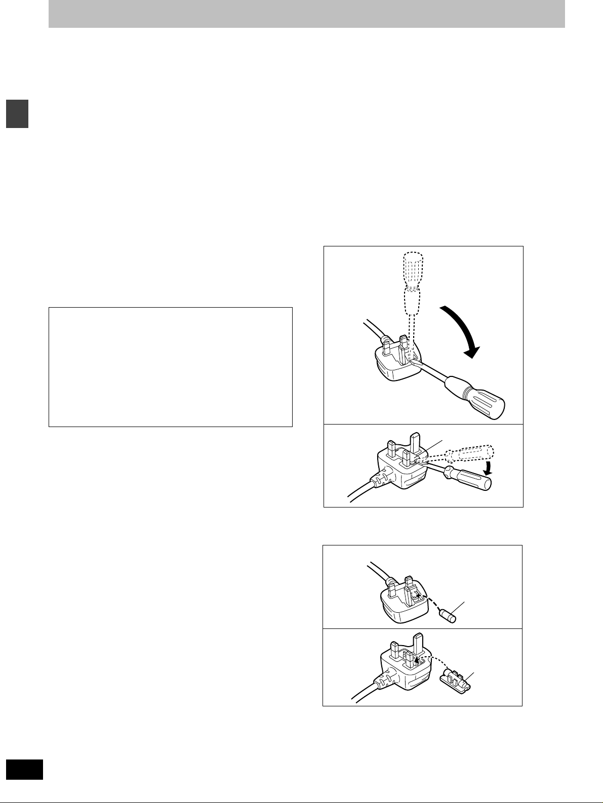
Caution for AC Mains Lead
(For United Kingdom)
(“EB” area code model only)
For your safety, please read the following text carefully.
This appliance is supplied with a moulded three pin
mains plug for your safety and convenience.
A 5-ampere fuse is fitted in this plug.
Should the fuse need to be replaced please ensure
that the replacement fuse has a rating of 5-ampere
and that it is approved by ASTA or BSI to BS1362.
Check for the ASTA mark Ï or the BSI mark Ì on the
Getting started
body of the fuse.
If the plug contains a removable fuse cover you must
ensure that it is refitted when the fuse is replaced.
If you lose the fuse cover the plug must not be used
until a replacement cover is obtained.
A replacement fuse cover can be purchased from your
local dealer.
CAUTION!
IF THE FITTED MOULDED PLUG IS
UNSUITABLE FOR THE SOCKET OUTLET IN
YOUR HOME THEN THE FUSE SHOULD BE
REMOVED AND THE PLUG CUT OFF AND
DISPOSED OF SAFELY.
THERE IS A DANGER OF SEVERE ELECTRICAL
SHOCK IF THE CUT OFF PLUG IS INSERTED
INTO ANY 13-AMPERE SOCKET.
If a new plug is to be fitted please observe the wiring
code as stated below.
If in any doubt please consult a qualified electrician.
WARNING: DO NOT CONNECT EITHER WIRE TO
THE EARTH TERMINAL WHICH IS MARKED WITH
THE LETTER E, BY THE EARTH SYMBOL Ó OR
COLOURED GREEN OR GREEN/YELLOW.
THIS PLUG IS NOT WATERPROOF—KEEP DRY.
Before use
Remove the connector cover.
How to replace the fuse
The location of the fuse differ according to the type of
AC mains plug (figures A and B). Confirm the AC
mains plug fitted and follow the instructions below.
Illustrations may differ from actual AC mains plug.
1. Open the fuse cover with a screwdriver.
Figure A
Figure B
Fuse cover
RQT6756
4
IMPORTANT
The wires in this mains lead are coloured in
accordance with the following code:
Blue: Neutral, Brown: Live.
As these colours may not correspond with the coloured
markings identifying the terminals in your plug,
proceed as follows:
The wire which is coloured Blue must be connected to
the terminal which is marked with the letter N or
coloured Black or Blue.
The wire which is coloured Brown must be connected
to the terminal which is marked with the letter L or
coloured Brown or Red.
2. Replace the fuse and close or attach the fuse
cover.
Figure A
Fuse
(5 ampere)
Figure B
Fuse
(5 ampere)
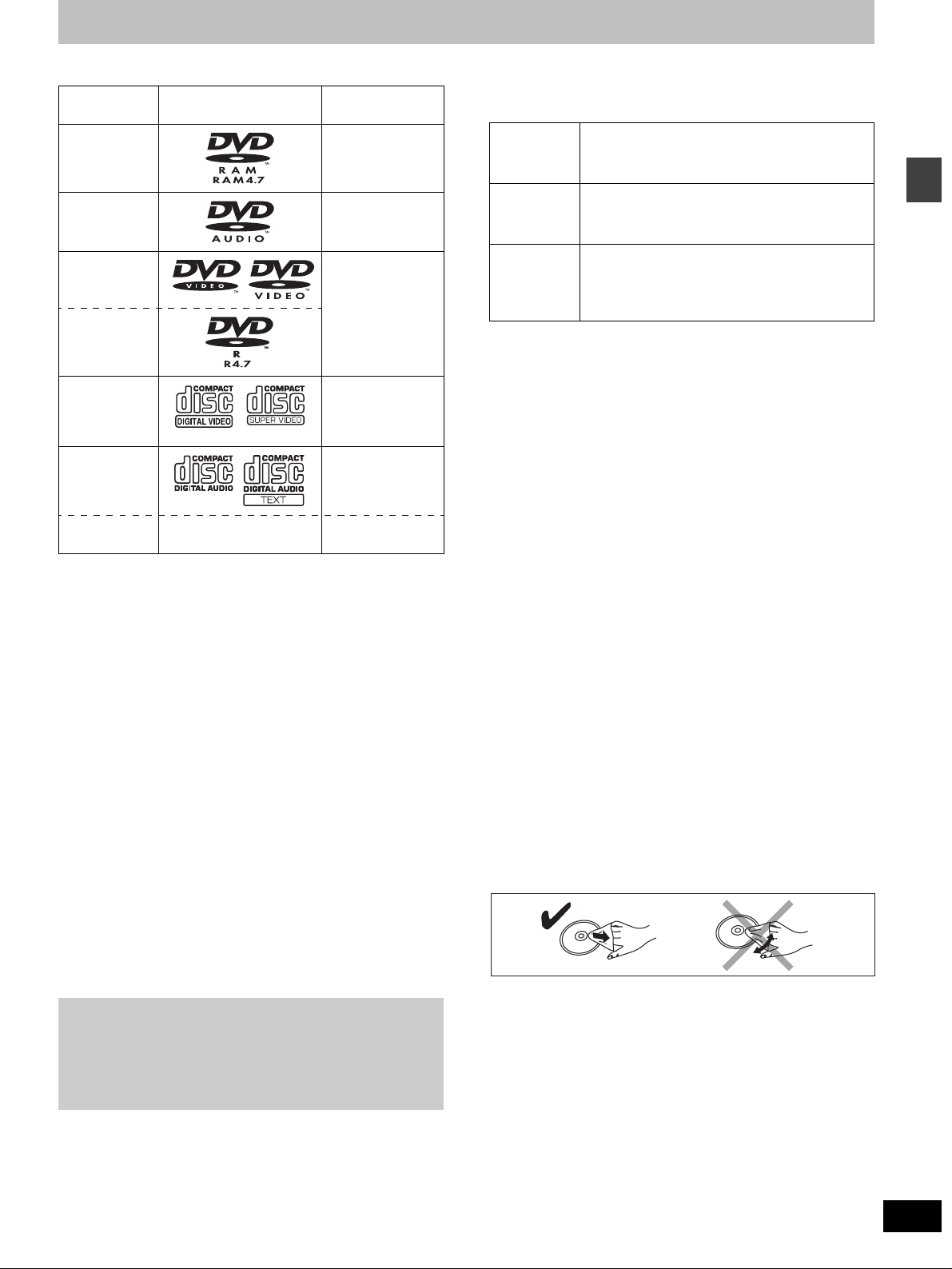
Disc information
∫ Discs that can be played
Disc type Logo Indication used
in instructions
DVD-RAM [RAM]
DVD-Audio [DVD-A]
DVD-Vi deo [DVD-V]
DVD-R
Video CD [VCD]
Including SVCD
(Confirming to
IEC62107)
CD [CD]
CD-R/RW — [WMA] [MP3]
≥Use discs with the above logos and that conform to specifications.
The unit cannot play other discs correctly.
≥Do not use irregularly shaped discs (e.g. heart-shaped), as these
can damage the unit.
Including CD text
[JPEG]
∫ Discs that cannot be played
DVD-ROM, CD-ROM, CDV, CD-G, iRW, DVD-RW, CVD, SACD,
Divx Video Discs, Photo CD and “Chaoji VCD” available on the
market including CVD, DVCD and SVCD that do not conform to
IEC62107.
∫ Disc structure
Disc structure and the labels given to the items on discs depend on
the disc type.
Track: the smallest division on DVD-Audio, CDs and Video CDs,
Chapter: the smallest division on DVD-Video.
Group: collections of tracks on DVD-Audio and equivalent to
Title:
Program: the division on DVD-RAM equivalent to a single
Picture: a single JPEG file.
Play list: the largest grouping on a HighMAT disc, or a group of
Scene: DVD-RAM program sections specified and grouped into
Content: covers tracks and pictures on HighMAT discs.
or a single WMA/MP3 file.
folders or albums on data discs.
the largest division on DVD-Video, usually an entire movie.
recording.
scenes on DVD-RAM.
play lists on a DVD video recorder.
Playing DVDs and Video CDs
The producer of these discs can control how they are played so
you may not always be able to control play as described in these
operating instructions (for example if the play time is not
displayed or if a Video CD has menus). Read the disc’s
instructions carefully.
∫ DVD-RAM discs
DVD-RAM discs must meet the following conditions for this unit to be
able to play them.
Ty p e ≥Non-cartridge discs
Capacity ≥12 cm 9.4 GB (double-sided) and 4.7 GB
Recording
format
≥Remove TYPE 2 and 4 discs from their cartridges before use, then
return them when you are finished. Read the instructions for the
disc carefully.
≥Do not allow the disc to become dirty or scratched. Store discs in
their cartridges and ensure the disc label and cartridge label face
the same way.
≥Some parts of the disc, for example where one program ends and
another begins, may not play smoothly.
≥Discs that can be removed from their
cartridges (TYPE 2 and 4)
(single-sided)
≥8 cm 2.8 GB (double-sided)
Discs recorded with DVD video recorders, DVD
video cameras, personal computers, etc., using
Version 1.1 of the Video Recording Format (a
unified video recording standard).
∫ DVD-R discs
Panasonic DVD-R recorded and finalized on a Panasonic DVD video
recorder are played as DVD-Video on this unit.
∫ CD-R and CD-RW discs
This unit can play CD-R/RW (audio recording disc) recorded with
CD-DA, video CD, SVCD (conforming to IEC62107), WMA, MP3 or
JPEG. Close the sessions or finalize the disc after recording.
∫ HighMAT discs
This unit is compatible with HighMAT discs containing WMA, MP3,
and/or JPEG files.
[Note]
It may not be possible to play CD-R, CD-RW, DVD-R and DVD-RAM
in all cases due to the type of disc or condition of the recording.
∫ Video systems
This unit can play both the PAL and NTSC for video systems. To
view PAL or NTSC, however, your television must match the system
used on the disc.
PAL discs cannot be correctly viewed on an NTSC television. NTSC
can be correctly viewed on a PAL television by converting the video
signal to PAL 60 (➡ page 33, Video—NTSC Disc Output).
∫ To clean discs
DVD-Audio, DVD-Video, Video CD, CD
Wipe with a damp cloth and then wipe dry.
DVD-RAM, DVD-R
≥Clean with an optional DVD-RAM/PD disc cleaner (LF-K200DCA1,
where available).
≥Never use cloths or cleaners for CDs etc.
∫ Handling precautions
≥Do not write on the label side with a ball-point pen or other writing
instrument.
≥Do not use record cleaning sprays, benzine, thinner, static
electricity prevention liquids or any other solvent.
≥Do not attach labels or stickers to discs. (Do not use discs with
exposed adhesive from tape or left over peeled-off stickers.)
≥Do not use scratch-proof protectors or covers.
≥Do not use discs printed with label printers available on the market.
Getting started
RQT6756
5
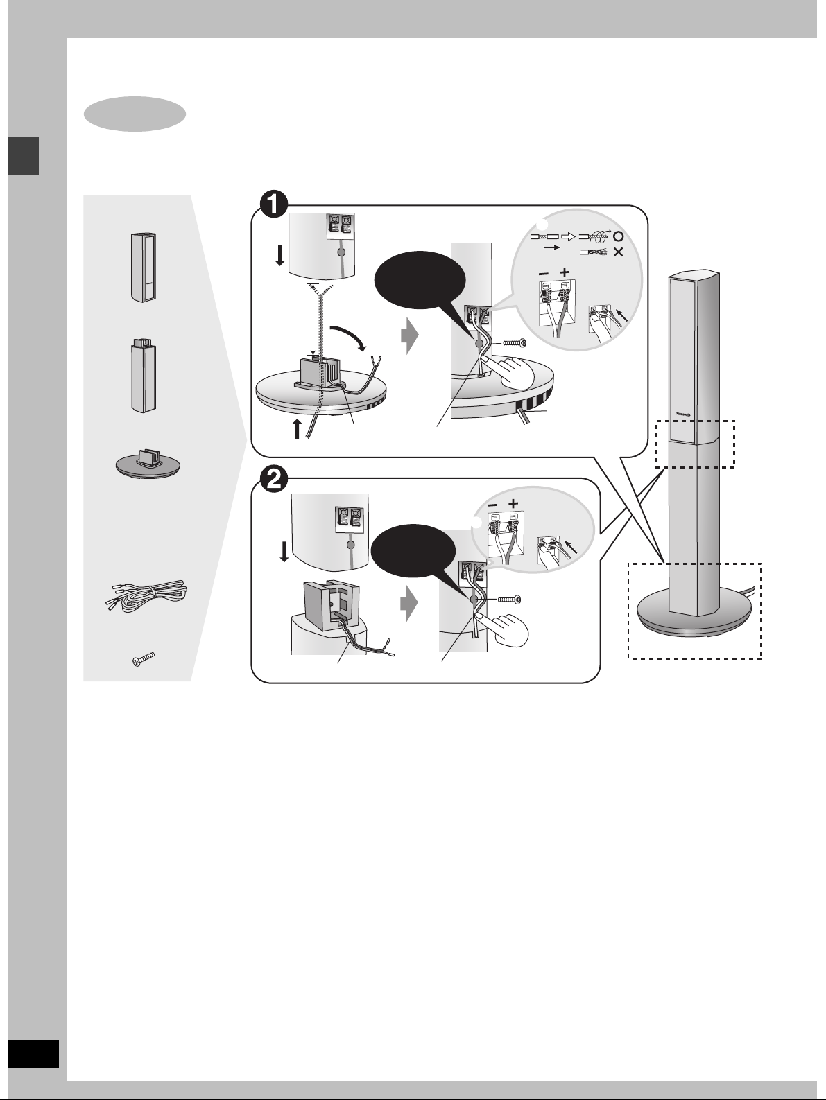
Simple setup
Simple setup
STEP
1
[HT900]
Assembly and connection of front and surround speakers
4 Speaker units
4 Stands
4 Bases
Speaker cables
≥2k4-m cables
≥2k10-m cables
4
Approx.
120 mm
2
31
2
Fit into
groove.
Confirm screw
is securely
fastened.
7
Place into groove.
Confirm screw
is securely
fastened.
4
5
_:
`:
6
8
Copper
Silver
Copper
_:
`:
Silver
Position wire
in grooves as
necessary
avoiding
knots.
Assembled
3
8 Silver screws
15
Fit into groove. Place into groove.
≥You can attach the speakers directly to their bases (if you want to put them on shelves, for example).
[Note]
≥Never short-circuit positive (i) and negative (j) speaker wires.
≥Be sure to connect only positive (copper) wires to positive (i) terminals and negative (silver) wires to negative (j) terminals.
Incorrect connection can damage the speakers.
RQT6756
6
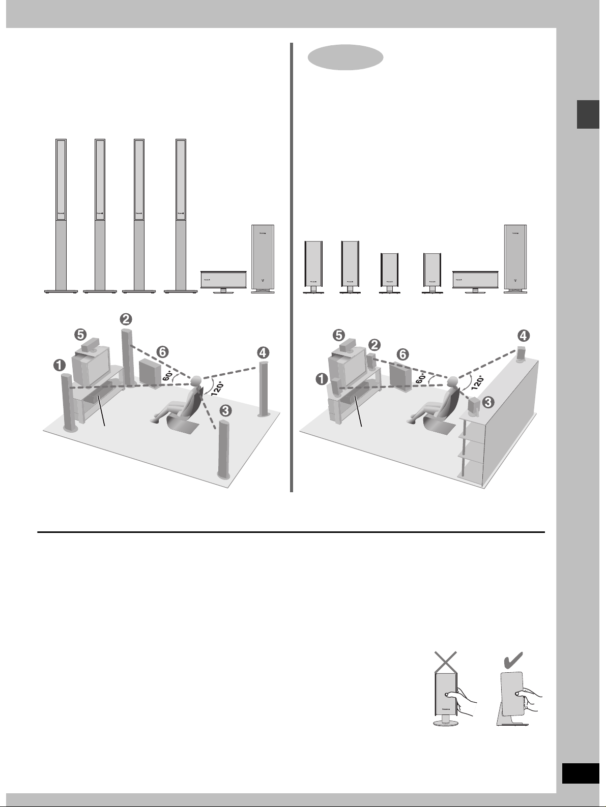
Locating
≥The front and surround speakers are the same. Use those you
have connected the short cords to as front speakers and those
you have connected the long cords to as surround speakers.
STEP
1
Locating
[HT700]
1
FRONT
(L)
2
FRONT
(R)
3
SURROUND
(L)
4
SURROUND
(R)
5
CENTER
6
SUBWOOFER
1
FRONT
(L)
Setup exampleSetup example
2
FRONT
(R)
3
SURROUND
(L)
4
SURROUND
(R)
5
CENTER
6
SUBWOOFER
Simple setup
Main unit
≥Place the front, center, and surround speakers at approximately the same distance from the seating position. The angles in the diagram are
approximate.
≥Use only supplied speakers
Using other speakers can damage the unit and sound quality will
be negatively affected.
≥Set the speakers up on an even surface to prevent them from
falling. Take proper precautions to prevent the speakers from
falling if you cannot set them up on an even surface.
Positioning for best effect
How you set up your speakers can affect the bass and the sound
field. Note the following points.
≥Place speakers on flat secure bases.
≥Placing speakers too close to floors, walls, and corners can result
in excessive bass. Cover walls and windows with thick curtain.
Main unit
Keep your speakers at least 10 mm away from the system for
proper ventilation.
Center speaker
≥You can also put this speaker directly under the television.
≥Vibration caused by the center speaker can disrupt the picture if it
is placed directly on the television. Put the center speaker on a
rack or shelf.
Subwoofer
Place to the right of the television, on the floor or a sturdy shelf so
that it won’t cause vibration.
Leave 10 cm on the right for the woofer to be effective. Leave
10 cm at the rear for ventilation.
Caution
Hold the speakers by the sides.
Applying pressure to the front net
can damage the speaker.
Main unit
RQT6756
7
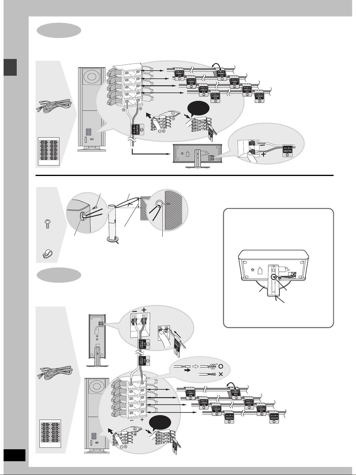
Simple setup
STEP
2
[HT900]
Connecting speakers with the subwoofer
Attach the speaker-cable stickers to make connection easier.
SUBWOOFER
1
2
4-m cable
Sheet of
speaker-cable
stickers
∫ Preventing the speakers from falling over
Screw
4 Black
screws
String (not included)
3
4
5
Click!
5 CENTER
1 FRONT (L)
2 FRONT (R)
3 SURROUND (L)
Copper
_:
`:
Silver
4 SURROUND (R)
RQT6756
8
Approx. 150 mm
4 Clips
STEP
Clip
[Note]
Consult a qualified building contractor when attaching the speakers to wall.
Improper attachment may result in damage to the wall and speakers.
2
[HT700]
Screw (not included)
Connecting speakers with the subwoofer
Attach the speaker-cable stickers to make connection easier.
1 FRONT (L)
Speaker cables
≥3k4-m cables
≥2k10-m cables
SUBWOOFER
Sheet of
speaker-cable
stickers
_:
Copper
`:
Silver
1
2
3
4
5
Click!
[Note]
≥Never short-circuit positive (i) and negative (j) speaker wires.
≥Be sure to connect only positive (copper) wires to positive (i)
[HT900] [HT700]
Keeping the cables out of the way
Pass the cables through the holes in the stand to
keep them out of the way.
Stand
1 Pass the cable
through the hole.
2 Pass through the
cutout in the base.
2 FRONT (R)
3 SURROUND (L)
4 SURROUND (R)
5 CENTER
terminals and negative (silver) wires to negative (j) terminals.
Incorrect connection can damage the speakers.
STEP
TV
AUDIO
IN
VCR
AUDIO
IN
AUX
LINE
OUT
COMPONENT
S-VIDEO
OUT
VIDEO
OUT
VIDEO OUT
P
B
P
R
Y
OPTICAL
IN
AM ANTFM ANT
EXTLOOP75
h
L
R
A
TV
AUDIO
IN
VCR
AUDIO
IN
AUX
LINE
OUT
COMPONENT
S-VIDEO
OUT
VIDEO
OUT
VIDEO OUT
P
B
P
R
Y
OPTICAL
IN
AM ANTFM ANT
EXTLOOP75
h
L
R
A
TV
AUDIO
IN
VCR
AUDIO
IN
AUX
LINE
OUT
COMPONENT
S-VIDEO
OUT
VIDEO
OUT
VIDEO OUT
P
B
P
R
Y
OPTICAL
IN
AM ANTFM ANT
EXTLOOP75
h
L
R
A
LINE
OUT
COMPONENT
S-VIDEO
OUT
VIDEO
OUT
VIDEO OUT
P
B
P
R
Y
L
R
AV
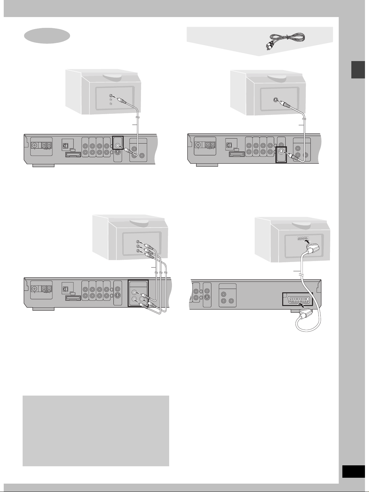
∫
Connecting a television with a VIDEO IN terminal
3
Television
Television
(not included)
VIDEO
IN
Video cable
∫
Connecting a television with an S-VIDEO IN terminal
S-VIDEO
IN
Video cable (included)
Connect directly to your television.
Do not connect the unit through a video cassette recorder, because
the picture may not be played correctly due to the copy guard.
∫ Connecting a television with COMPONENT
VIDEO IN terminals
COMPONENT
VIDEO IN
R
P
B
P
Y
Video cables (not included)
S-video cable (not included)
S-VIDEO OUT terminal
The S video terminal achieves a more vivid picture than the VIDEO
OUT terminal by separating the chrominance (C) and luminance
(Y) signals. (Actual results depend on the television.)
[For\the\United\Kingdom\and\Russia]
∫ Connecting a television with SCART terminal
AV
21-pin SCART cable (not included)
Simple setup
COMPONENT VIDEO OUT terminals
These terminals can be used for either interlace or progressive
output and provide a purer picture than the S-VIDEO OUT
terminal. Connection using these terminals outputs the color
difference signals (P
B/PR) and luminance signal (Y) separately in
order to achieve high fidelity in reproducing colors.
≥The description of the component video input terminals depends
on the television or monitor (e.g. Y/P
B/PR, Y/B-Y/R-Y, Y/CB/CR).
Connect to terminals of the same color.
[For\the\United\Kingdom\and\Russia]
≥When making this connection, set “Video Out (AV/Component)”
to “Video/Y PB PR” or “S-Video/Y PB PR” from QUICK SETUP
(➡ page 12).
To enjoy progressive video
≥Connect to the component video (480P) input terminals on a
television compatible with this unit’s copy guard system.
(Video will not be displayed correctly if connected to an
incompatible television.)
≥When playing NTSC discs, change video output mode to
“480P” (➡ page 26).
≥Press [PROGRESSIVE] on the main unit so “PROG.” appears
on the display (➡ page 14).
≥All televisions manufactured by Panasonic and that have 480P
you have another brand of television.
input connectors are compatible. Consult the manufacturer if
SCART (AV) terminal
To improve picture quality, you can change the video signal output
from the SCART (AV) terminal from “Video” to either “S-Video” or
“RGB” to suit the type of television you are using. Set “Video Out
(AV/Component)” to “S-Video/Y PB PR” or “RGB/No Output” from
QUICK SETUP (➡ page 12).
RQT6756
9
STEP
TV
AUDIO
IN
VCR
AUDIO
IN
AUX
LINE
OUT
S-VIDEO
OUT
VIDEO
OUT
OPTICAL
IN
AM ANTFM ANT
EXTLOOP75
h
L
R
A
AM ANTFM ANT
EXTLOOP75
h
GND
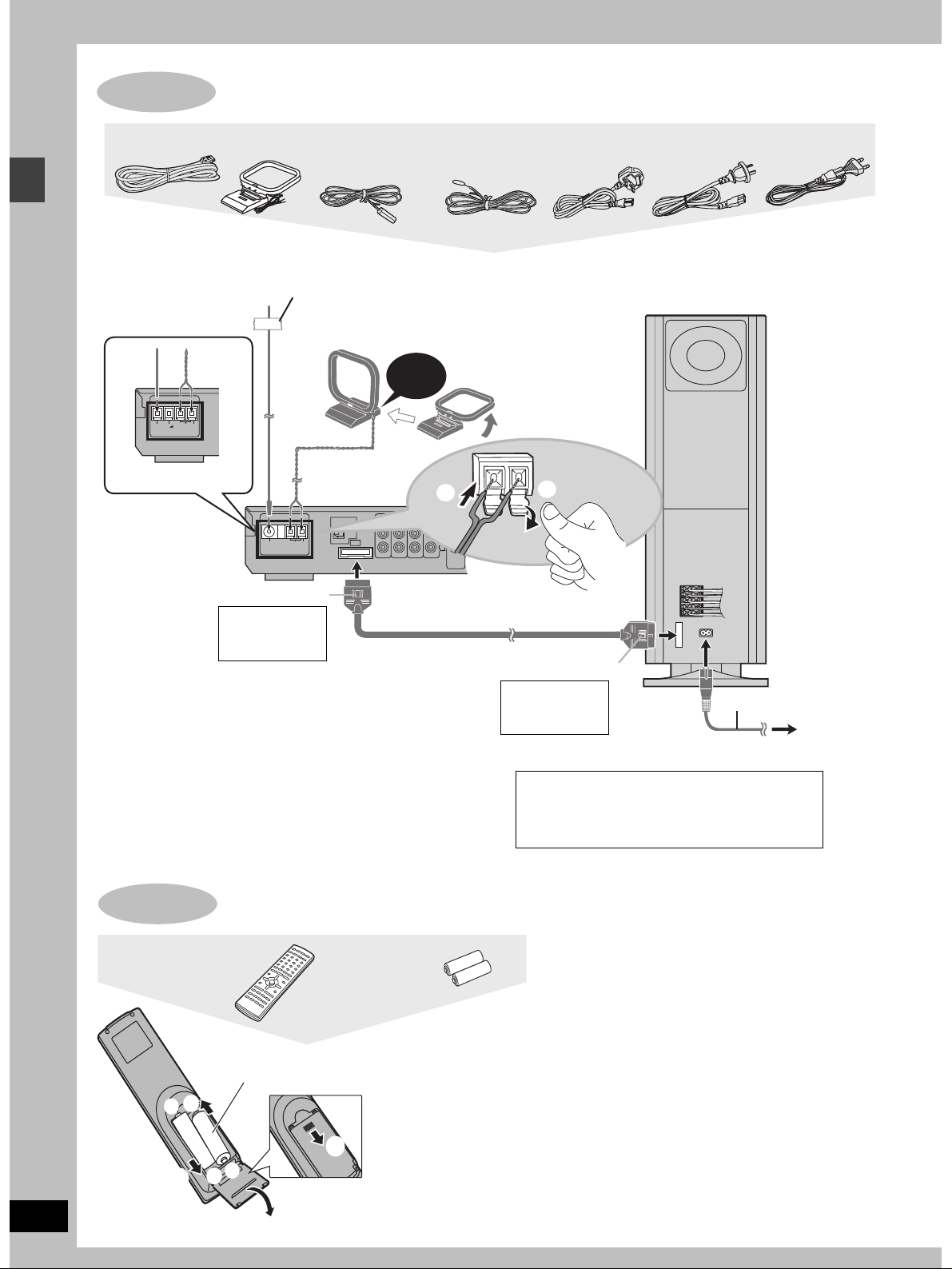
5
4
Connecting the subwoofer, antennas, and AC mains lead
Simple setup
System cable
AM loop
antenna
FM indoor antenna AC mains lead
[For\the\United\Kingdom]
\and\Russia]
[For\Australia\and\N.Z.]
Connect the AC mains lead after all
other connections are complete.
FM indoor antenna
Adhesive tape
Fix the other end of the antenna
where reception is best.
Click!
[For\Australia\and\N.Z.]
2
Catch up
To disconnect
Press the catch
and pull out.
Conserving power
The unit consumes power (approx. 0.7 W) even when it is turned
off with [Í]. To save power when the unit is not to be used for a
long time, unplug it from the household mains socket.
Remember to reset the radio stations and any other memory
items before using the unit again.
Information you enter into the unit’s memory remains intact for up
to 2 weeks after the AC mains lead is disconnected.
System cable
[For\the\United\Kingdom] [For\Australia\and\N.Z.] [For\Russia]
Subwoofer
AM loop antenna
Stand the antenna up
on its base.
Keep loose antenna
cord away from other
wires and cords.
1
1
L
2
R
3
L
4
R
5
A
Catch to the right
To disconnect
Press the catch
and pull out.
[For\the\United\Kingdom\only]
BE SURE TO READ THE CAUTION FOR THE
AC MAINS LEAD ON PAGE 4 BEFORE
CONNECTION.
AC mains lead
To household
mains socket
RQT6756
10
STEP
Remote control
+
3
The remote control
R6/LR6, AA, UM-3
3
-
1
+
-
2
Batteries
≥Insert so the poles (i and
j) match those in the
remote control.
≥Do not use rechargeable
type batteries.
Do not;
≥mix old and new batteries.
≥use different types at the same time.
≥heat or expose to flame.
≥take apart or short circuit.
≥attempt to recharge alkaline or manganese batteries.
≥use batteries if the covering has been peeled off.
Mishandling of batteries can cause electrolyte leakage which
can damage items the fluid contacts and may cause a fire.
Remove if the remote control is not going to be used for a long
period of time. Store in a cool, dark place.
∫ Use
Aim at the sensor, avoiding obstacles, at a maximum range of
7 m directly in front of the unit.
Other speaker setup options
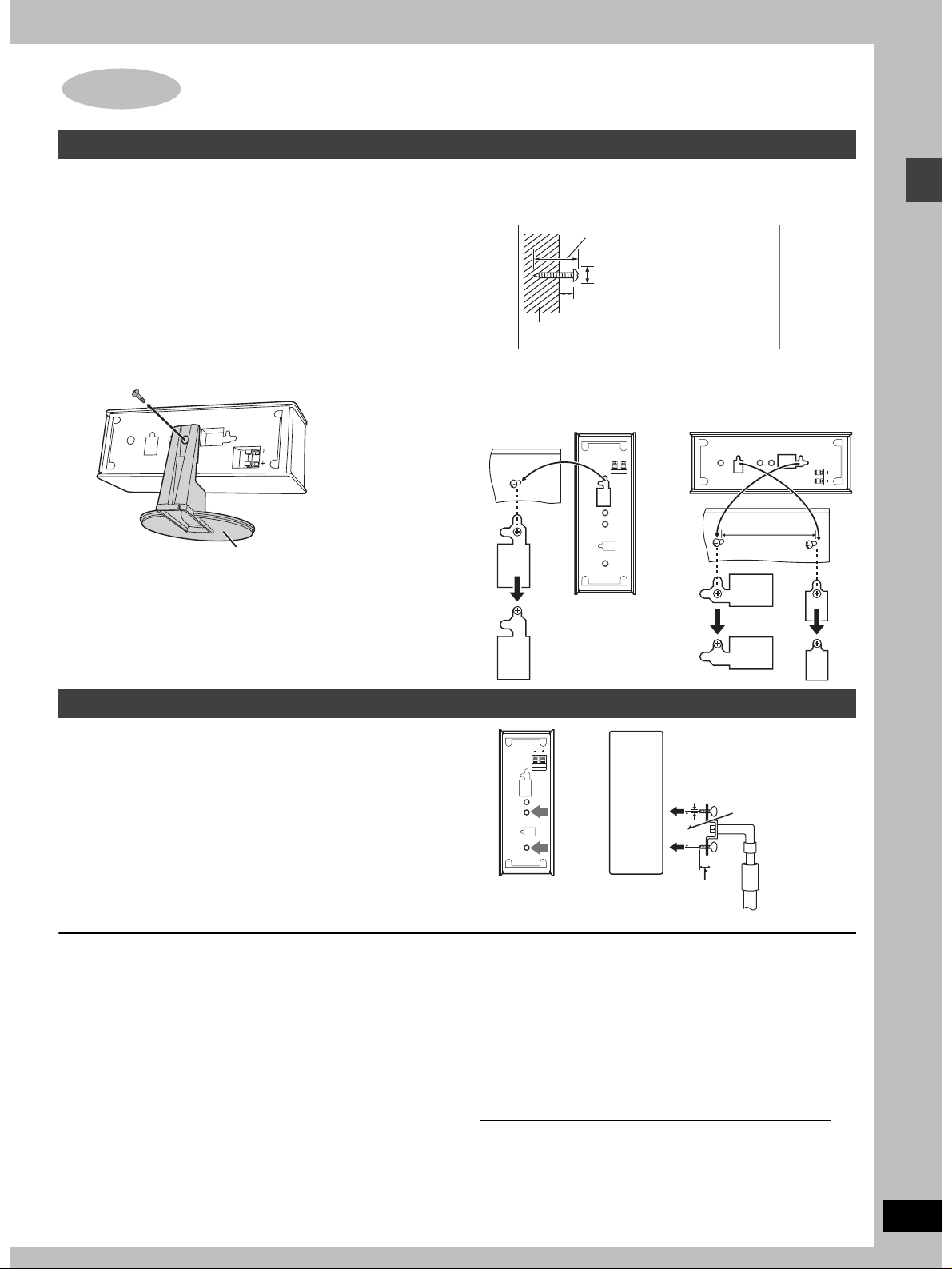
Attaching to a wall
[HT900] (Center speaker only) / [HT700]
[Note]
The wall or pillar on which the speakers are to be attached should
be capable of supporting 10 kg per screw.
1 Remove the stand.
BEFORE REMOVING THE STAND
≥Take the speaker cable out of the stand’s hole if it is
threaded through.
≥Lay the speaker on a soft cloth.
Unscrew the screw with a Phillips-head screwdriver.
Stand
2 Screw a screw (not included) into the
wall.
30– 35 mm
‰7.5–9.4 mm
8– 11 mm
Wall
3 Fit the speaker securely onto the
screw with the hole or holes.
Vertical Horizontal
100 mm
Simple setup
Fitting speaker stands (optional)
[HT900] (Center speaker only) / [HT700]
Preparation
Remove the stand (➡ step 1 above).
Ensure the stands meet these conditions before purchasing them.
≥Observe the diameter and length of the screws and the distance
between screws as shown in the diagram.
≥The stands must be able to support over 10 kg.
≥The stands must be stable even if the speakers are in a high
position.
Notes on speaker use
≥You can damage your speakers and shorten their useful life if you
play sound at high levels over extended periods.
≥Reduce the volume in the following cases to avoid damage.
–When playing distorted sound.
–When the speakers are receiving howling from a record player,
noise from FM broadcasts, or continuous signals from an
oscillator, test disc, or electronic instrument.
–When adjusting the sound quality.
–When turning the unit on or off.
If irregular coloring occurs on your television
These speakers are designed to be used close to a television, but
the picture may be affected with some televisions and setup
combinations.
If this occurs, turn the television off for about 30 minutes.
The television’s demagnetizing function should correct the problem.
If it persists, move the speakers further away from the television.
5 mm, pitch 0.8 mm
60 mm
Attach the stands
with these holes.
Caution
≥Use the speakers only with the recommended
system. Failure to do so may lead to damage to the
amplifier and/or the speakers, and may result in the
risk of fire. Consult a qualified service person if
damage has occurred or if you experience a sudden
change in performance.
≥Do not attempt to attach these speakers to walls
using methods other than those described in this
manual.
Plate thickness plus 7
to 10 mm
Speaker stand
(not included)
RQT6756
11
Simple setup
STEP
6
1
4–7
QUICK SETUP
AV SYSTEM
TV VCR
DIGITAL
AUX
TV/AV
DISC
PAGE
GROUP
SEQUENTIAL
REPEAT
PLAY MODE
TOP MENU
DIRECT
NAVIGATOR
DISPLAY
TV VOL
SUBWOOFER
LEVEL
SLEEP
C.S.M
SHIFT
TUNER/BAND DVD/CD
123
DISC 1 DISC 2
456
DISC 4 DISC 5
7809
FL DISPLAY
CANCEL
SKIP
SLOW/SEARCH
CH
ENTER
s
VOLUME
C.FOCUS
S.POSITION
SFC
S.SRND
ZOOM
AV EFFECT
P.MEMORY
AUDIO
DR COMP
TEST
CH SELECT
QUICK REPLAY
DISC 3
S
10/-/--
MENU
PLAY LIST
RETURN
TV VOL
r
MIX 2CH
PL
SETUP
MUTING
DELAY TIME
SUBTITLE
2
RETURN
3, 7
3, 7
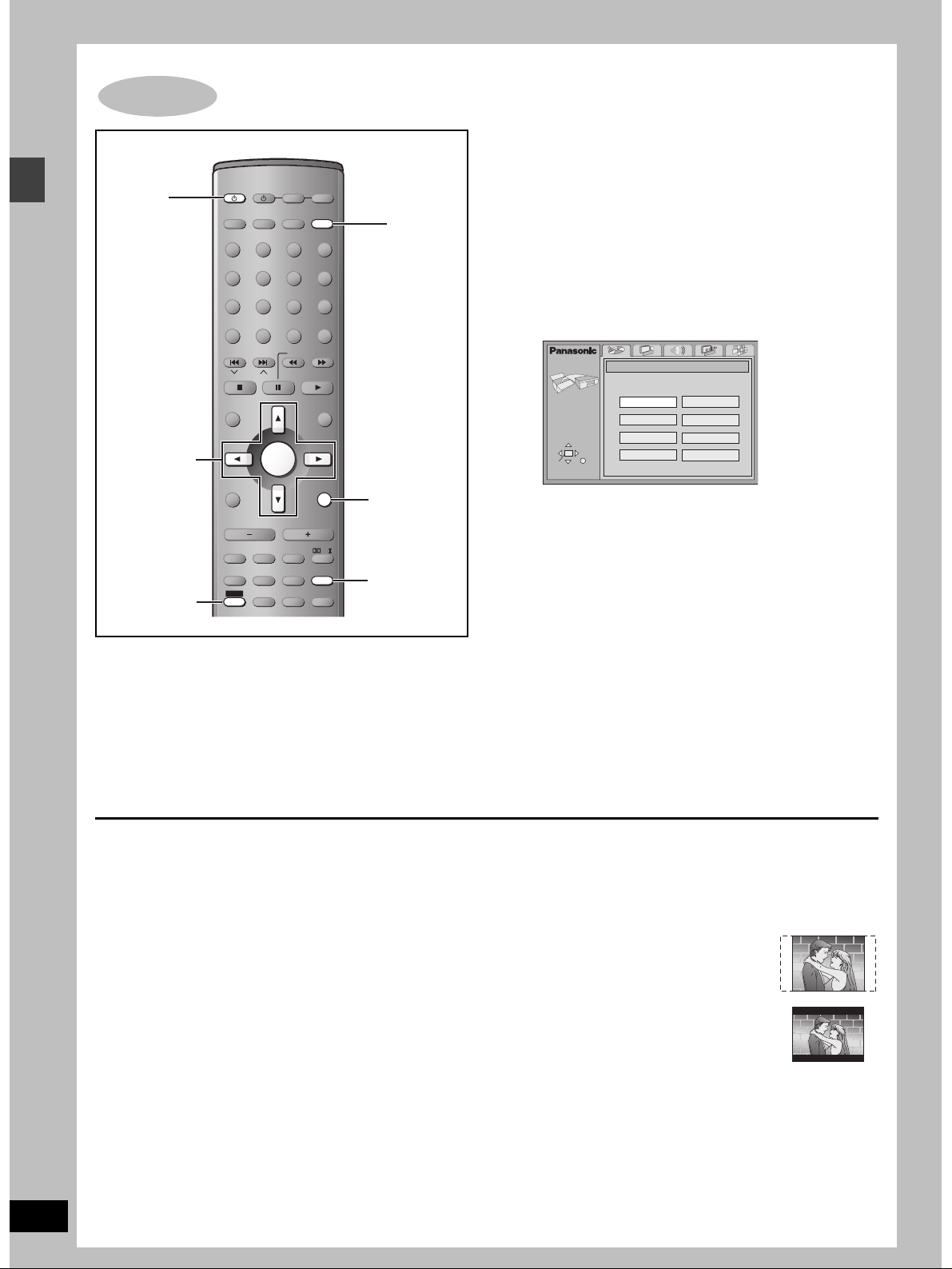
The QUICK SETUP screen appears when you press [SHIFT]i
[SETUP] the first time after purchase and assists you to make
necessary settings. You can access this screen again later if you
need to (➡ page 33, Others— QUICK SETUP).
Preparation
Turn on the television and select the appropriate video input on the
television to suit the connections for the unit.
1 Press [Í] to turn on the unit.
2 Press [DVD/CD] to select “DVD/CD”
as the source.
3 Press [SHIFT]i[SETUP] to show the
QUICK SETUP screen.
SETUP
SELECT
ENTER RETURN
QUICK SETUP
Select the menu language.
English
Deutsch
Español
Svenska
Français
Italiano
Português
Nederlands
4 Press [3, 4, 2, 1] to select the
menu language and press [ENTER].
5 Press [3, 4] to select “Yes” to
continue and press [ENTER].
6 Press [3, 4, 2, 1] to select the item
and press [ENTER].
≥Audio Language (➡ page 33)
≥Subtitle Language (➡ page 33)
≥TV Type (➡ below)
≥TV Aspect (➡ below)
[For\the\United\Kingdom\and\Russia]
≥Video Out (AV/Component) (➡ page 33)
7 Press [ENTER] and then [SHIFT]i
[SETUP] to end the settings.
RQT6756
12
To return to the previous screen
Press [RETURN].
∫ TV Type
Select to suit the type of television.
≥Standard (Direct View TV) (factory preset)
≥CRT Projector
≥LCD TV/Projector
≥Projection TV
≥Plasma TV
∫ TV Aspect
Select “4:3” (regular) or “16:9” (widescreen) to suit your
television.
If you have a regular 4:3 television, you can also select how video
on some discs is shown (➡ page 33, Video—TV Aspect).
≥4:3 Pan&Scan (factory preset)
Widescreen software is expanded to fill the
screen of a 4:3 aspect television (unless
prohibited by the producer of the disc).
≥4:3 Letterbox
Widescreen software is shown in the
letterbox style on a 4:3 aspect television.
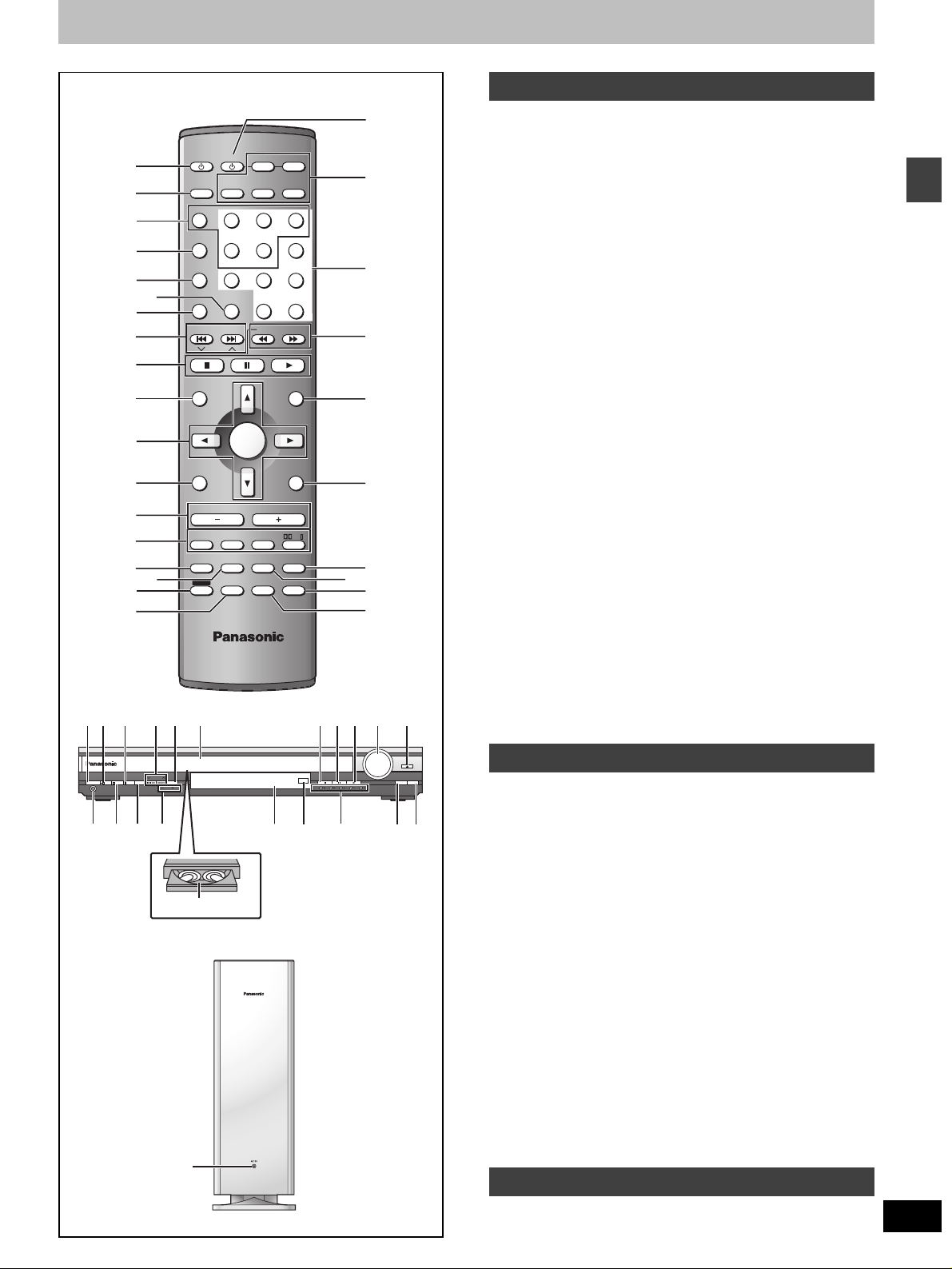
Control reference guide
C
AV SYSTEM
1
2
3
4
5
6
TV/AV
DISC
PAGE
GROUP
SEQUENTIAL
REPEAT
PLAY MODE
TV VCR
DIGITAL
TUNER/BAND DVD/CD
AUX
123
DISC 1 DISC 2
456
DISC 4 DISC 5
7809
FL DISPLAY
CANCEL
DISC 3
S
10/-/--
D
E
7
8
SKIP
SLOW/SEARCH
CH
F
9
C.FOCUS
S.SRND
ZOOM
AUDIO
DR COMP
DELAY TIME
QUICK REPLAY
[
MENU
PLAY LIST
RETURN
TV VOL
MIX 2CH
PL
SETUP
MUTING
SUBTITLE
r
TUNE MODETUNING FM MODE MEMORY
12345
DISCV.R.S M.R.S
J
G
H
I
K
L
UTSRNM PQ
V
VOLUME
OPEN/CLOSE
DOWN
UP
DISC EXCHANGE
DISC SKIP
^
_\
@
TOP MENU
DIRECT
NAVIGATOR
DISPLAY
s
TV VOL
SUBWOOFER
LEVEL
SLEEP
C.S.M
SHIFT
ENTER
VOLUME
S.POSITION
SFC
AV EFFECT
P.MEMORY
TEST
CH SELECT
:
;
<
=
>
?
A
B
1
/
I
Í
PHONES
W Z]
X
O
PROGRESSIVE
DIGITAL IN
C.S.M
Y
SELECTOR
5
4
5
4
Disc tray number
`
1 Standby/on switch [Í] . . . . . . . . . . . . . . . . . . . . . . . . . . . . . . 12
2 TV/AV button [TV/AV] . . . . . . . . . . . . . . . . . . . . . . . . . . . . . . . 36
3 Disc select button [DISC], Disc buttons [DISC1]–[DISC5] . . 14
4 Group, Page button [GROUP, PAGE]. . . . . . . . . . . . . . . . 16, 17
5 Sequential button [SEQUENTIAL]. . . . . . . . . . . . . . . . . . . . . 15
6 Cancel, FL display button [CANCEL, FL DISPLAY] . . . . 19, 32
7
8 Skip, Preset channel, TV channel button
9 Basic operation buttons. . . . . . . . . . . . . . . . . . . . . . . . . . . . . 14
: Top menu, Direct navigator button
; Cursor buttons [3, 4, 2, 1], Enter button [ENTER] . . . . . 12
<
= Volume buttons [s, r, VOLUME]. . . . . . . . . . . . . . . . . . . . . . 14
> Sound field, sound quality buttons. . . . . . . . . . . . . . . . . 28–31
?
@ [HT900] Position memory, AV effect button
A Shift button [SHIFT]
B Channel select, Test button [CH SELECT, TEST] . . . . . 28, 29
C AV system standby/on button [Í, AV SYSTEM] . . . . . . . . . 36
D Source select buttons
E Numbered buttons [1– 9, 0, S10/-/--] . . . . . . . . . . . . . . . . . . . 16
F Slow/search, Tuning buttons
G Menu, Play list button [MENU, PLAY LIST]. . . . . . . . . . . 14, 21
H Return, TV volume up button [RETURN, TV VOLr] . . . 12, 36
I Muting, Setup button [MUTING, SETUP] . . . . . . . . . . . . 12, 32
J Audio, Zoom button [AUDIO, ZOOM] . . . . . . . . . . . . . . . 18, 20
K [HT900] Subtitle, Delay time button
L [HT900]
1 Standby/on switch [Í/I] . . . . . . . . . . . . . . . . . . . . . . . . . . . . . 12
M Standby/on indicator
N Custom Sound Memory button [C.S.M] . . . . . . . . . . . . . . . . 30
O Skip/search, Tuning buttons
P Source select button [SELECTOR]
Q Drawer
R Stop, Tune mode button [∫, TUNE MODE]. . . . . . . . . . . 14, 27
S Pause, FM mode button [;, FM MODE] . . . . . . . . . . . . . 14, 27
T Play, Memory button [1, MEMORY] . . . . . . . . . . . . . . . . 14, 27
U Volume control [VOLUME, DOWN, UP] . . . . . . . . . . . . . . . . . 14
V Drawer open/close button [<, OPEN/CLOSE]. . . . . . . . . . . 14
W Headphone jack [PHONES] . . . . . . . . . . . . . . . . . . . . . . . . . . 32
X [HT900] DIGITAL IN button [DIGITAL IN] . . . . . . . . . . . . . . . . . 37
Y Progressive out button [PROGRESSIVE]. . . . . . . . . . . . . . . 14
Z [HT900] Multi rear surround, Virtual rear surround indicators
[ Display
\ Remote control signal sensor
] Disc indicators [DISC 1–5] . . . . . . . . . . . . . . . . . . . . . . . . . . . 14
^ Disc exchange button [DISC EXCHANGE] . . . . . . . . . . . . . . 15
_ Disc skip button [DISC SKIP] . . . . . . . . . . . . . . . . . . . . . . . . 15
` AC supply indicator [AC IN]
Remote control
Play mode, Repeat button [PLAY MODE, REPEAT]
[: 9, SKIP, X CH W] . . . . . . . . . . . . . . . . . . . . . 16, 27, 36
[TOP MENU, DIRECT NAVIGATOR] . . . . . . . . . . . . . . . . . 14, 21
Display, TV volume down button [DISPLAY, TV VOLs]
[HT900]
Dolby Pro Logic
II
button [
ÎPLII
]
[HT700] Dolby Pro Logic button [ÎPL]
Custom sound memory, Sleep button [C.S.M, SLEEP]
[P.MEMORY, AV EFFECT]. . . . . . . . . . . . . . . . . . . . . . . . . 15, 29
[HT700] Position memory button [POSITION MEMORY] . . . . 15
To use functions labeled in orange:
While pressing [SHIFT], press the corresponding button.
Face towards this unit to change the source.
Press [TV] or [VCR] first to operate a Panasonic television or
video cassette recorder (➡ pages 36, 37).
[HT900] AUX, DIGITAL input button [AUX, DIGITAL]
[HT700] AUX button [AUX]
[6, 5 SLOW/SEARCH] . . . . . . . . . . . . . . . . . . . . . . . 16, 27
[SUBTITLE, DELAY TIME] . . . . . . . . . . . . . . . . . . . . . . . . 18, 30
[HT700] Subtitle button [SUBTITLE] . . . . . . . . . . . . . . . . . . . . 18
Quick replay, Dynamic range compression button
[QUICK REPLAY, DR COMP] . . . . . . . . . . . . . . . . . . . . . . 15, 31
[HT700] Quick replay button [QUICK REPLAY]. . . . . . . . . . . . 15
. . . . . 17, 19
. . 24, 36
. . 30, 32
Main unit
Press to switch the unit from on to standby mode or vice versa.
In standby mode, the unit is still consuming a small amount of power.
When the unit is connected to the AC mains supply, this indicator
lights up in standby mode and goes out when the unit is turned on.
[:/6, 5/9, X TUNING W] . . . . . . . . . . . . . . . . . 16, 27
[HT900] DVD/CD>FM>AM>TV>VCR>AUX>DIGITAL IN
[HT700] DVD/CD>FM>AM>TV>VCR>AUX
[M.R.S, V.R.S] . . . . . . . . . . . . . . . . . . . . . . . . . . . . . . . . . . . . . 29
Subwoofer
This indicator lights when the unit is connected to the AC mains
supply.
Getting started
RQT6756
13
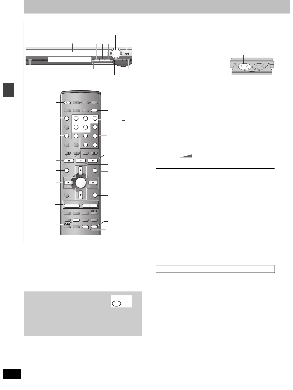
Discs—Basic play
–
%
@@
PROGRESSIVE
SELECTOR
S.M
V.R.S M.R.S
PROGRESSIVE
Í
DISC
Disc operations
SEQUENTIAL
∫
TOP MENU
342 1
ENTER
%
P.MEMORY
[RAM] [DVD-A] [DVD-V] [VCD] [CD] [WMA] [MP3] [JPEG]
Preparation
≥Press [Í] to turn on the unit.
≥Turn on the television and select the appropriate video input on the
television to suit the connections for the unit.
Disc indicators
AV SYSTEM
DIGITAL
AUX
TV/AV
DISC
123
DISC 1 DISC 2
PAGE
GROUP
456
DISC 4 DISC 5
SEQUENTIAL
7809
FL DISPLAY
REPEAT
PLAY MODE
CANCEL
SKIP
CH
TOP MENU
DIRECT
NAVIGATOR
ENTER
DISPLAY
s
TV VOL
VOLUME
SUBWOOFER
S.POSITION
LEVEL
SFC
SLEEP
AV EFFECT
P.MEMORY
C.S.M
TEST
SHIFT
CH SELECT
∫;
TUNE MODETUNING FM MODE MEMORY
12345
DISC
DISC EXCHANGE
TV VCR
TUNER/BAND DVD/CD
DISC 3
S
10/-/--
SLOW/SEARCH
MENU
PLAY LIST
RETURN
TV VOL
r
C.FOCUS
MIX 2CH
S.SRND
PL
ZOOM
SETUP
AUDIO
MUTING
DR COMP
DELAY TIME
QUICK REPLAY
SUBTITLE
DOWN
!
DISC 1
DISC 5
Numbered
buttons
$
;
MENU
RETURN
SUBTITLE
QUICK REPLAY
,
#$
VOLUME
OPEN/CLOSE
UP
DISC EXCHANGE
DISC SKIP
DISC SKIP
If the disc contains both audio data (WMA and MP3) and
JPEG, check “Mixed Disc—Audio & Stills” setting in the
SETUP menu (➡ page 33). Select “Stills (JPEG)” or “Audio
(MP3/WMA)”.
≥Remove TYPE 2 and 4 discs
from their cartridges before use.
Play starts from the disc in
the front-left position.
[RAM]
≥Label-up (With double-sided
discs, load so the label for the
side you want to play is facing
1
1
5
up.)
[3] Press [<] to close the drawer.
The disc indicator lights red to show the disc in the play
position is selected.
[4] Press [1] (play).
Play begins.
[WMA] [MP3] [CD] (CD text only)
Group and track names are displayed on the television.
≥Press [SUBTITLE] to turn the display on or off.
≥You can also use the navigation menus to control play
(➡ page 22).
[5] Adjust the volume.
– dB
(Minimum) (Maximum)
∫ To pause play
Press [;] during play.
Press [1] (play) to restart play.
∫ To stop play
Press [∫] (➡ page 15, Resume function).
∫ To select a disc
Press [DISC] and then the disc button ([DISC 1]–[DISC 5]).
∫ To prevent damage
Do not;
≥load more than one disc per tray.
≥touch the drawer or the carousel while they are in motion.
≥rotate the carousel by hand.
≥close the drawer by hand.
[Note]
≥If “$” appears on the television
The operation is prohibited by the unit or disc.
≥It may take some time for play to start but this is normal.
When a menu appears on the television
0 dB
5
RQT6756
14
[1] Press [DVD/CD] to select “DVD/CD” as
the source.
To enjoy progressive video
Press [PROGRESSIVE].
The television will be disrupted for a
moment but this is normal.
≥Output from this unit is interlace if you have connected to the
television through the VIDEO OUT, S-VIDEO OUT or SCART
(AV) terminal or playing PAL discs, even if “PROG.” is on the
display.
PROG
.
[2] Press [<] to open the drawer and
place the disc(s) on the disc tray(s).
To load discs on the other trays, press [DISC SKIP] on the
main unit.
[DVD-A] [DVD-V] [VCD]
Press the numbered buttons to select an
item.
To select a 2-digit number
Example: To select item 23, press [S10] ➡ [2] ➡ [3].
≥When playing DVDs, you can also use [3, 4, 2, 1] to select
items. Press [ENTER] to confirm your selection.
To return to the menu screen
[DVD-A] [DVD-V] [TOP MENU]: Shows the first menu screen.
[DVD-V] [MENU]: Shows the menu screen.
[VCD] [RETURN]: Shows the menu screen.
[Note]
The disc continues to rotate while the menu is displayed even after
you finish playing an item. Press [∫] when you finish to preserve the
unit’s motor and your television screen.
 Loading...