

Page 1
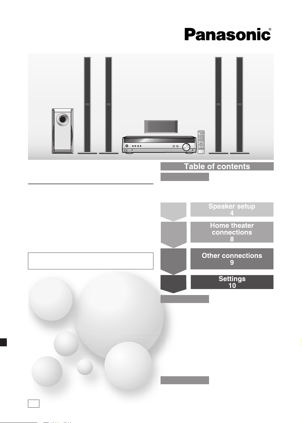
Operating Instructions
SC-HT60
Table of contents
Home Theater Audio System
Model No. SC-HT40
SC-HT60
Dear customer
Thank you for purchasing this product.
Please read these instructions carefully before connecting,
operating or adjusting this product.
Please keep this manual for future reference.
SC-HT 60 is used in t he illustratio ns un less ot herwise
mentioned.
Before use
Safety precautions ......................................... 2
Supplied accessories ....................................3
The remote control .........................................3
Step 1
Step 2
Speaker setup
4
Home theater
connections
8
Step 3
Other connections
9
Step 4
Settings
10
Operations
Basic operations ..........................................12
Control guide ................................................13
Making a recording ......................................15
The RESET function .....................................15
MENU operation ...........................................16
The radio ....................................................... 17
Sound field ....................................................
Other functions ............................................20
Other settings ...............................................21
Remote control operation guide .................22
Specifications ...............................................
18
23
GN
Reference
Troubleshooting guide .................Back cover
Maintenance ..................................Back cover
RQTV0110-1B
Page 2
2
RQTV0110
Safety precautions
Placement
Set the unit up on an even surface away from direct sunlight, high
temperatures, high humidity, and excessive vibration. These conditions
can damage the cabinet and other components, thereby shortening the
unit's service life.
Do not place heavy items on the unit.
Voltage
Do not use high voltage power sources. This can overload the unit and
cause a fire.
Do not use a DC power source. Check the source carefully when
setting the unit up on a ship or other place where DC is used.
AC mains lead protection
Ensure the AC mains lead is connected correctly and not damaged.
Poor connection and lead damage can cause fire or electric shock. Do
not pull, bend, or place heavy items on the lead.
Grasp the plug firmly when unplugging the lead. Pulling the AC mains
lead can cause electric shock.
Safety Precautions
Do not handle the plug with wet hands. This can cause electric shock.
Foreign matter
Do not let metal objects fall inside the unit. This can cause electric
shock or malfunction.
Do not let liquids get into the unit. This can cause electric shock or
malfunction. If this occurs, immediately disconnect the unit from the
power supply and contact your dealer.
Do not spray insecticides onto or into the unit. They contain flammable
gases which can ignite if sprayed into the unit.
Service
Do not attempt to repair this unit by yourself. If sound is interrupted,
indicators fail to light, smoke appears, or any other problem that is
not covered in these operating instructions occurs, disconnect the AC
mains lead and contact your dealer or an authorized service center.
Electric shock or damage to the unit can occur if the unit is repaired,
disassembled or reconstructed by unqualified persons.
Extend operating life by disconnecting the unit from the power source
if it is not to be used for a long time.
This product may receive radio interference caused by mobile
telephones during use. If such interference is apparent, please
increase separation between the product and the mobile
telephone.
TH IS UNI T IS INT END ED FOR U SE IN MODERA TE
CLIMATES.
WARNING:
TO REDUCE THE RISK OF FIRE, ELECTRIC SHOCK
OR PRODUCT DAMAGE, DO NOT EXPOSE THIS
APPARATUS TO RAIN, MOISTURE, DRIPPING OR
SPLASHING AND THAT NO OBJECTS FILLED WITH
LIQUIDS, SUCH AS VASES, SHALL BE PLACED ON
THE APPARATUS.
The socket outlet shall be installed near the equipment and
easily accessible or the mains plug or an appliance coupler
shall remain readily operable.
CAUTION!
•
DO NOT INSTALL OR PLACE THIS UNIT IN A BOOKCASE,
BUILT-IN CABINET OR IN ANOTHER CONFINED SPACE.
ENSURE THE UNIT IS WELL VENTILATED. TO PREVENT
RISK OF ELECTRIC SHOCK OR FIRE HAZARD DUE
TO OVERHEATING, ENSURE THAT CURTAINS AND
ANY OTHER MATERIALS DO NOT OBSTRUCT THE
VENTILATION VENTS.
• DO NOT OBSTRUCT THE UNIT’S VENTILATION
OPENINGS WITH NEWSPAPERS, TABLECLOTHS,
CURTAINS, AND SIMILAR ITEMS.
• DO NOT PLACE SOURCES OF NAKED FLAMES, SUCH
AS LIGHTED CANDLES, ON THE UNIT.
• DISPOSE OF BATTERIES IN AN ENVIRONMENTALLY
FRIENDLY MANNER.
CAUTION!
Do not place anything on top of this unit or block the heat
radiation vents in any way. In particular, do not place tape
decks or CD/DVD players on this unit as heat radiated from it
can damage your software.
If you see this symbol-
Information on Disposal in other Countries outside the
European Union
This symbol is only valid in the European Union.
If you wish to discard this product, please contact
your local authorities or dealer and ask for the correct
method of disposal.
Page 3
3
RQTV0110
System SC-HT40 SC-HT60
(N2QAYB000010)
3
2
2
1
VOLUME
TV/VIDEO
MUTIN
G
VOLUME
SUBWOOFER
1
2 3
708
9
10
4 5
6
>
=
^
AV
SYSTEM
RECEIVER
DVR/DVD-P
TUNER
BAND
TV
TV
^
INPUT SELECTOR
TUNE
MENU
RETURN
SETUP
MUSIC PORT
VOLUME
ENTER
SC-HT60
AV Control Receiver SA-HT40 SA-HT60
Front speakers SB-PF41 SB-FS61
Surround speakers SB-PS41 SB-FS62
Center speaker SB-PC40 SB-PC41
Subwoofer SB-W40 SB-W40
Supplied accessories
Please check and identify the supplied accessories.
1 AC mains lead
1 AM loop antenna
1 FM indoor antenna
1 speaker sticker sheet
The remote control
R6/LR6, AA, UM-3
Ins ert so the poles (+ and -) match those in the remote
•
control.
Do not use rechargeable type batteries.
•
Use
Aim at the sensor, avoiding obstacles, at a maximum range of
7 m directly in front of the unit.
Remote control signal sensor
2 Batteries
16 Screws
1 Speaker cable
2 Speaker stands with
long cables
1 Remote control
4 Stand bases
2 Speaker stands with
short cables
7 meters
Transmission window
Note
•
Keep the transmission window and the unit's sensor free from
dust.
Operation can be affected by strong light sources, such as
•
direct sunlight, and the glass doors on cabinets.
Supplied accessories/The remote control
Page 4
4
RQTV0110
1
FRONT
L
FRONT
L
FRONT
R
FRONT
R
SURROUND
L
SURROUND
L
SURROUND
R
SURROUND
R
C
(center)
1
FRONT
L
FRONT
L
2
FRONT
R
FRONT
R
SURROUND
L
SURROUND
L
SURROUND
R
SURROUND
R
C
(center)
C
(center)
C
(center)
SUB
(subwoofer)
SUB
(subwoofer)
SUB
(subwoofer)
SUB
(subwoofer)
3344556
6
1
2 3 4 5 6
1
2
3
45612
Step
1
1
2
3
4
5
6
SC-HT60
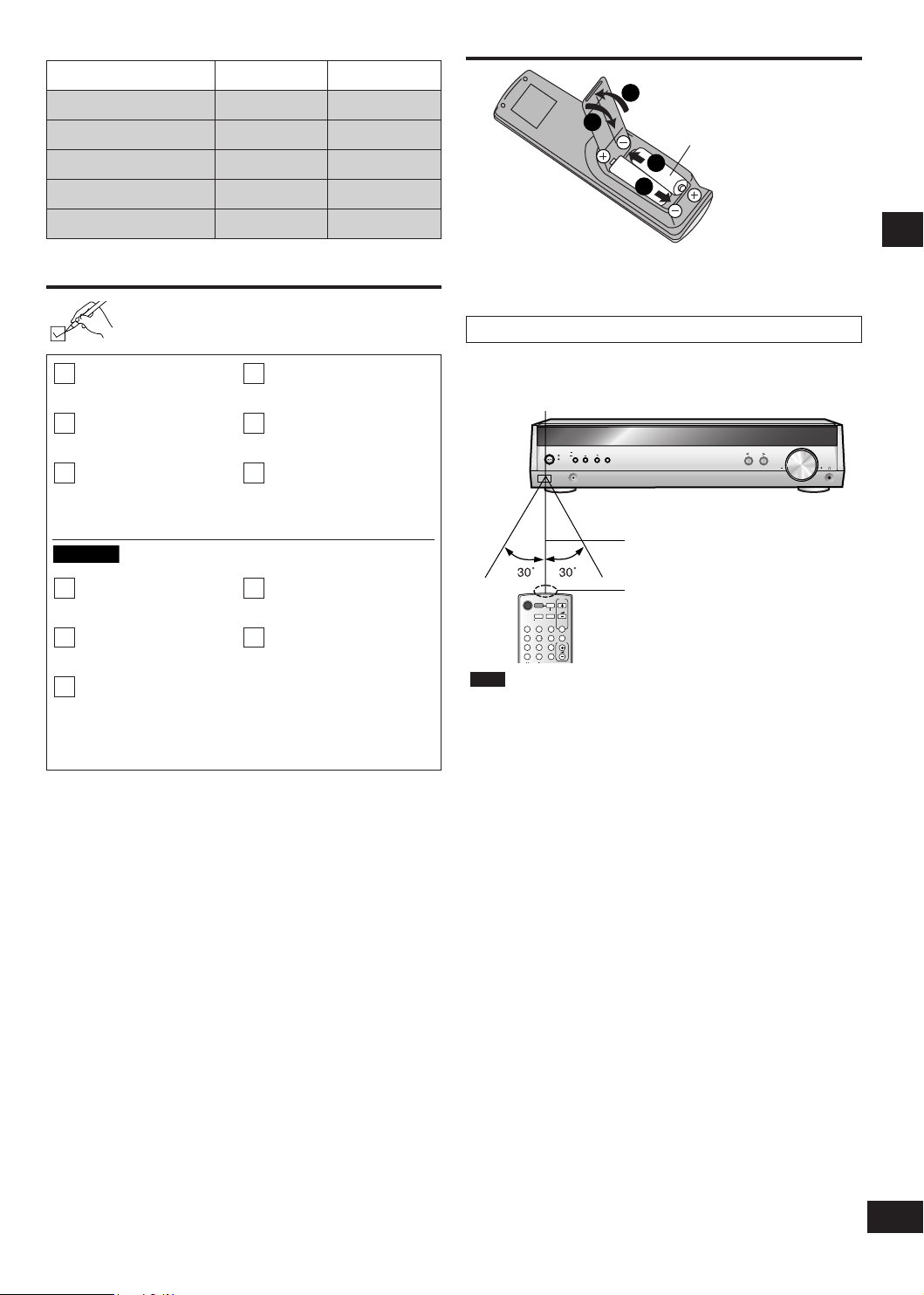
Placement of speakers.
Example:
Speaker setup
Supplied
accessories
Sticker sheet
Front
speaker (L)
Step 1 Speaker setup
Center speaker
Front speaker (R)
Subwoofer
Surround
speaker (R)
Positioning for best effect
How you set up your speakers can affect the bass and the
sound field.
Note the following points.
Place speakers on flat secure bases.
•
Placing speakers too close to floors, walls, and corners can
•
result in excessive bass. Cover walls and windows with a
thick curtain.
Note
Keep your speakers at least 10 mm away from the system for
proper ventilation.
Surround
speaker (L)
Place the front, center, and surround speakers at approximately the same distance from the seating position.
The angles in the diagram are approximate.
Front speakers (left, right)
Place on the left and right of the TV at seated ear height so that there is good coherency between the picture and sound.
Center speaker
Place underneath or above the center of the TV. Aim the speaker at the seating area.
Surround speakers (left, right)
Place on the side of or slightly behind the seating area, higher than ear level.
Subwoofer
The subwoofer can be placed in any position as long as it is at a reasonable distance from the TV.
Note that some experimentation can yield the smoothest low frequency performance. Placement near a corner can increase the
apparent output level, but can result in unnatural bass.
If irregular colouring occurs on your television
The supplied speakers are designed to be used close to a
television, but the picture may be affected with some televisions
and setup combinations.
If this occurs, turn the television off for about 30 minutes.
The television's demagnetising function should c orrect the
problem. If it persists, move the speakers further away from the
television.
Caution
The main unit and supplied speakers are only to be
•
used as indicated in this manual. Failure to do so may
lead to damage to the receiver and/or the speakers,
and may result in the risk of fire. Consult a qualified
service person if damage occurs or if a sudden change
in performance is apparent.
Do not attempt to attach these speakers to walls using
•
methods other than those described in this manual.
Page 5
5
RQTV0110
2
SC-HT60
2
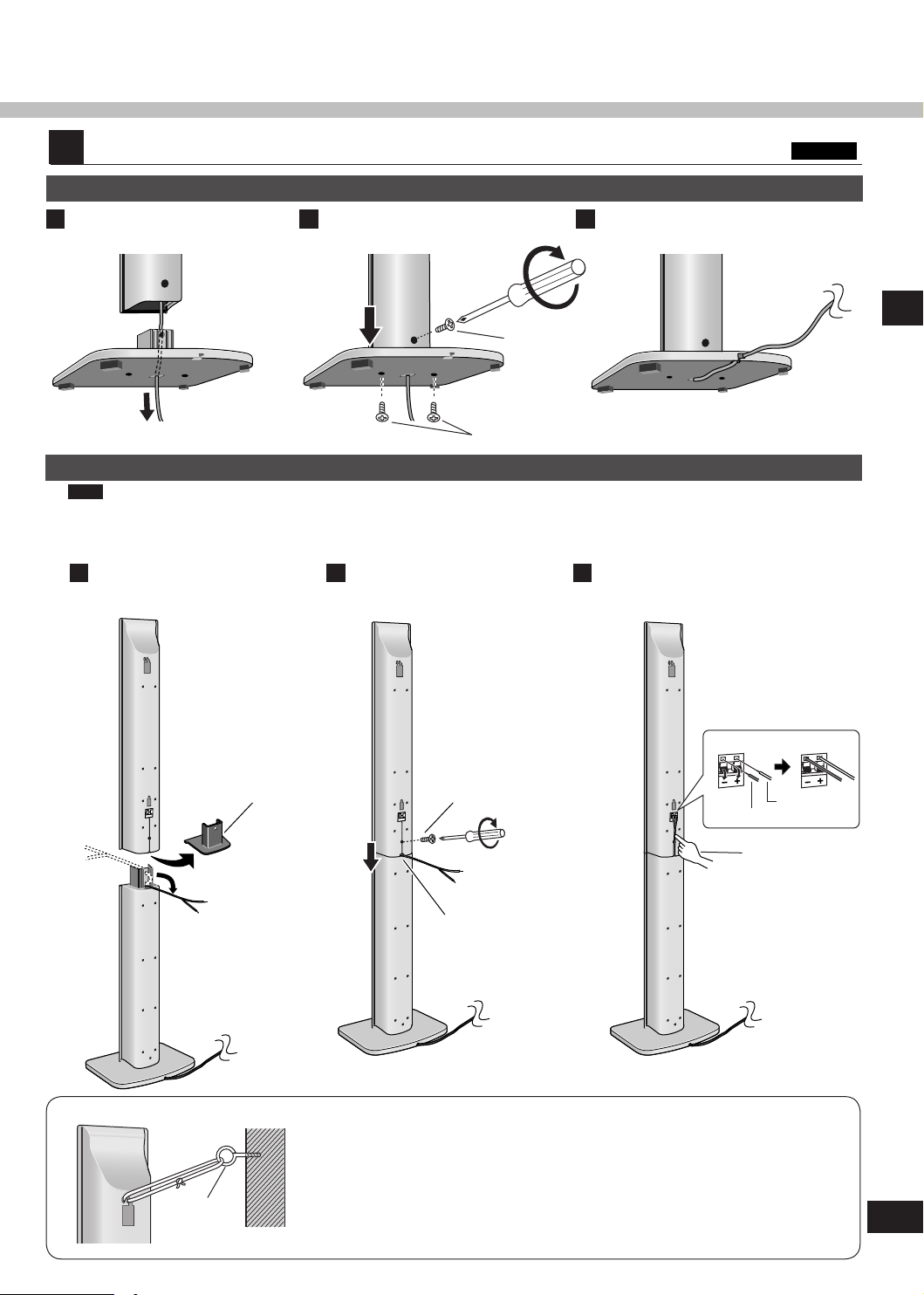
Front and surround speaker assembly
Attaching the stand to the base
Thread the speaker cable
1
through the base.
2
Secure the speaker stand to
the base.
Fasten screw
Fasten the speaker cable to
3
the base.
Step 1
Fasten screws
Attaching the speaker to the stand
Note
Before attaching, check the speaker label.
SB-FS61: Use as front speakers. Attach the stands with the short cables.
•
SB-FS62: Use as surround speakers. Attach the stands with the long cables.
•
Remove the cover from the
1
bottom of the speaker and
attach the speaker to the stand.
Cover
Secure the speaker to the
speaker stand.
Fasten screws
Thread speaker cable
through slot
Connect the speaker cables.
32
white with blue stripe
Speaker setup
white
Press the speaker
cable into the
groove
screw eye
wall
Preventing the speakers from falling over
Attach screw eyes (not included) to secure the speakers to a wall (diagram on the
left).
Obtain the screws appropriate to the walls and pillars to which they are going to
•
be fastened.
Consult with a qualified housing contractor concerning the appropriate procedure
•
when attaching to a concrete wall or a surface that may not have strong enough
support. Improper attachment may result in damage to the wall or speakers.
Page 6
6
RQTV0110
SUB
SPEAKERS
R
C SURROUND FRONT
R L L
6
Ω
4
Ω
6 5 4 3 2 1
CENTER
SURROUND
L
SURROUND R
SUBWOOFER
FRONT R
FRONT L
4
FRONT
L
1
FRONT
R
SURROUND
L
SURROUND
R
C
(center)
SUB
(subwoofer)
2
34
5
6
SC-HT40
SC-HT60
SC-HT40
SC-HT60
SC-HT40
SC-HT60
SC-HT40
SC-HT60
SC-HT60
3
1
3
5
2
4
6
FRONT
L
FRONT
L
FRONT
R
FRONT
R
SURROUND
L
SURROUND
L
SURROUND
R
SURROUND
R
C
(center)
1
FRONT
L
FRONT
L
2
FRONT
R
FRONT
R
SURROUND
L
SURROUND
L
SURROUND
R
SURROUND
R
C
(center)
C
(center)
C
(center)
SUB
(subwoofer)
SUB
(subwoofer)
SUB
(subwoofer)
SUB
(subwoofer)
3344556
6
1
2 3 4 5 6
1
2
3
456
1
2
FRONT
L
FRONT
L
1
1
FRONT
L
1
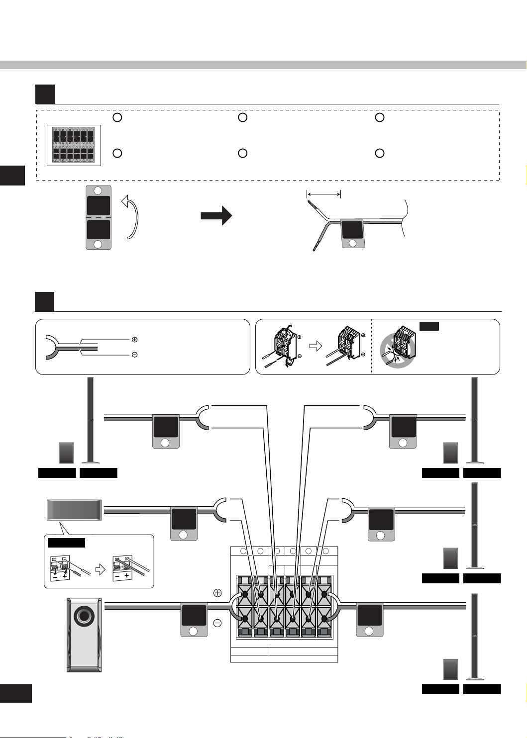
Attach the stickers to the speaker cables.
Step 1 Speaker setup
Front speaker (L)
SC-HT40: SB-PF41
SC-HT60: SB-FS61
Front speaker (R)
SC-HT40: SB-PF41
SC-HT60: SB-FS61
Connect the speakers to the receiver.
White cord
White cord with blue stripe
Surround speaker (L)
SC-HT40: SB-PS41
SC-HT60: SB-FS62
Surround speaker (R)
SC-HT40: SB-PS41
SC-HT60: SB-FS62
About 10 cm
Center speaker
SC-HT40: SB-PC40
SC-HT60: SB-PC41
Subwoofer
(SB-W40)
Note
Neve r short -c ircuit
p o s it i v e (+ ) a n d
negative (-) speaker
wires.
Page 7
7
RQTV0110
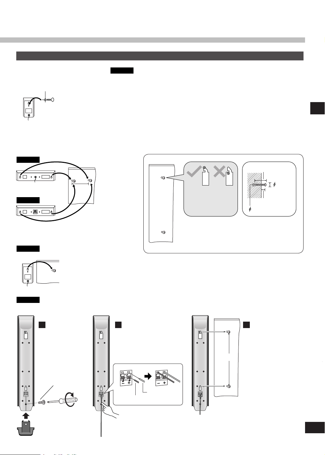
Other speaker setup options
SC-HT40
335 mm
SC-HT60
SC-HT40
7.5 - 9.4 mm
3.0 - 4.0 mm
7.5 -
9.4 mm
30 - 35 mm
4 - 7 mm
3.0- 4.0 mm
SC-HT60
SC-HT40
Fitting optional speaker stands
e.g. Front and surround speakers
5mm, Pitch 0.8 mm
Use the same screw type for the center speaker.
•
The stands must be able to support over 10 kg.
•
The stands must be stable even if the speakers are in a high position.
•
Attaching to a wall
Center speaker
Speaker setup Step 1
200 mm
Wall or pillar
Front and surround speakers
Wall or pillar
Use new cables when attaching the speakers to the wall.
Secure the cover
1
at the bottom of
the speaker.
Press the speaker cable
into the groove.
Ensure that the screws
are securely positioned
wh en atta c hin g t he
speakers to the wall.
The wall or pillar on which the speakers are to be
attached should be capable of supporting 10 kg per
screw. Consult a qualified building contractor when
attaching the speakers to wall. Improper attachment
may result in damage to the wall and speakers.
Fix screws at 335 mm
32
apart onto the wall.
Fasten screws
white with blue stripe
white
Page 8
8
RQTV0110
2
Step
SUB
SPEAKERS (HAUT-PARLEURS)
R
C SURROUND FRONT
R L L
6
Ω
4
Ω
6 5 4 3 2 1
FM
ANT
AM
ANT
75 Ω
LOOP
EXT
LOOP
ANT
GND
OPT 2 OPT 1
COAXIAL
DVR/DVD-P
TV
DIGITAL IN
TV
GAME/AUX
AUDIO
DVR/DVD-P
L
R
L
R
L
R R
L
IN IN OUT IN
SPEAKERS
R
C SURROUND FRONT
R L L
6~8
Ω
4~8
Ω
DIGITAL AUDIO
OUT
VIDEO OUT
VIDEO IN
AUDIO IN
AUDIO OUT
OPT 2
DVR/DVD-P
L
R R
L
IN OUT
DVR/DVD-P
DIGITAL AUDIO
OUT
VIDEO OUT
VIDEO IN
FRONT (L, R)
AUDIO OUT
OPT 2
DVR/DVD-P
DVR/DVD-P
L
R
IN
DIGIT
AL A
UDIO OUT
COAXIAL
DIGITAL AUDIO
OUT
AUDIO OUT
TV
L
R
IN
OPT 1
TV
AUDIO OUT
GAME/AUX
L
R
IN
VIDEO IN
VIDEO OUT
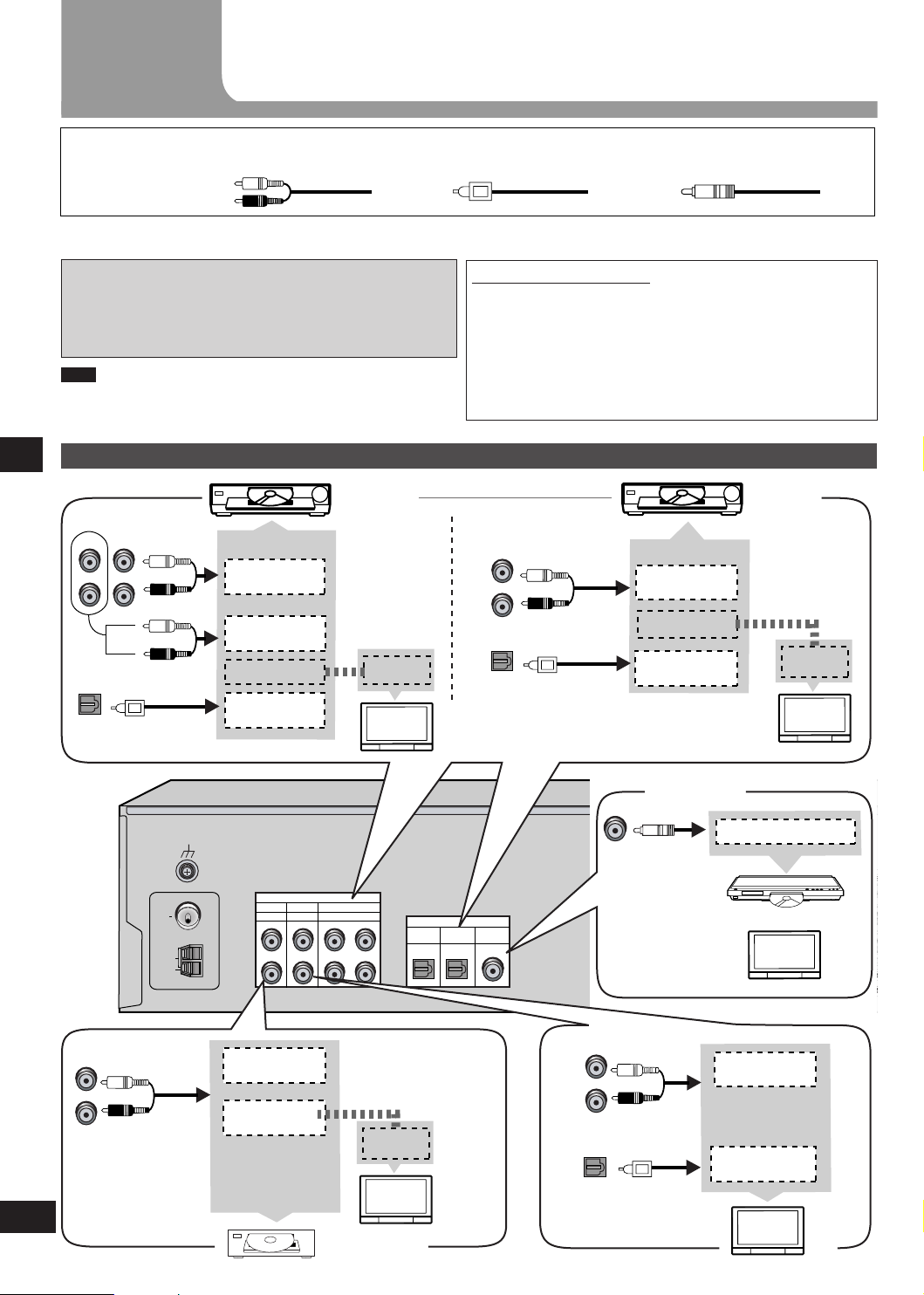
Home theater connections
Other
accessories
Stereo phono cable
(not included)
Left
Right
Turn off all components before making any connections.
To connect equipment, refer to the appropriate operating instructions.
Changing the digital input settings
You can change the input settings for the digital terminals if
necessary. Note the equipment you have connected to the
terminals, then change the settings. One of the terminals will
remain unused, whatever the setting. (➡ page 10)
•
Note
Use digital connection to enjoy Dolby Digital or DTS.
•
Do not bend the optical fibre cable.
•
Step 2Home theater connections
TV, DVR/DVD-P and Game/Aux
DVR
Connect the
video cable
d i r e c tl y to
the TV.
Optical fibre cable
(not included)
Notes on digital input
This unit can decode the following signals:
Dolby Digital, DTS
•
PCM, including PCM with sampling frequencies of 96 or
•
88.2 kHz
It cannot decode:
Other digital signals, such as MPEG
•
Dolby Digital RF signals from a laser disc player
•
TV
(Monitor)
Coaxial cable
(not included)
DVD
player
Connect the
vi d eo cabl e
directly to the
TV.
TV
(Monitor)
Game/Aux
Connect the
video cable
d i r e c tl y to
the TV.
TV
(Monitor)
Coaxial
DVR or DVD
player
TV
or
TV
Page 9

9
RQTV0110
FM
ANT
AM
ANT
75
Ω
LOOP
EXT
TV
GAME/AUX
AUDIO
LOOP
ANT
GND
DVR/DVD-P
L R L
R
L
R R
L
OPT 2 OPT 1
COAXIAL
DVR/DVD-P
TV
DIGITAL IN
AC IN
~
IN IN OUT IN
AC IN
~
SUB
SPEAKERS
R
C SURROUND FRONT
R L L
6
Ω4Ω
6 5 4 3 2 1
LOOP
ANT
GND
2
3
1
1
2
FM
ANT
AM
ANT
75 Ω
LOOP
EXT
AC IN~AC IN
~
3
(x 1)
(x 1)
(x 1)
Step
Other connections
Supplied
accessories
FM indoor antenna
(included)
Adhesive tape
Fix the end of the antenna where
reception is best.
AC mains lead FM indoor antenna
For best reception
FM outdoor antenna (not
included)
Disconnect the FM indoor
•
antenna.
The an t e n n a sho u l d be
•
inst al led by a co mpetent
technician.
Black
White
Red
Keep the antenna cord away from DVD players and other cords.
AM loop antenna
FM outdoor antenna
Click!
75 Ω coaxial cable Antenna plug
AM loop antenna (included)
The cooling fan operates at high power output levels only.
AC mains lead (included)
Connect this cord after all other cables are
Household AC mains socket
connected.
(AC 230-240 V/50 Hz)
Conserving power
The unit consumes 1 W even when it is turned off with [8]. To save power when the unit is not to be used for
a long time, unplug it from the household AC mains socket. You will need to reset some memory items after
plugging in the unit.
Note
The included AC mains lead is for use with this unit only. Do not use it with other equipment.
•
Do not use an AC mains lead from any other type of equipment with this unit.
•
Other connections Step 3
Page 10

10
RQTV0110
4
T E S T L
TUNE
TUNE
D I S TA N C E
D I G I N PU T
L C R SR SL SUBW
MENU
RETURN
SETUP
ENTER ENTER ENTER
-LEVEL
TEST
Step
Change the settings to suit your equipment to the environment in which you are using it. Before making any changes, read the
descriptions of the settings, note the factory settings and ranges, and refer to the equipment's instructions.
Settings
DISTANCE
Enter the distance of
the front, cent er an d
surr o u n d sp e a k e r s
f r o m t h e s e a ti n g
position.
DIG INPUT
(digital input)
Step 4Settings
Change the distance so that the
sound from all the speakers (except
for the subwoofer) reaches you at
the same time.
You can select distances between
1.0 and 10.0 m.
The factory settings are:
LR (front):
C (center):
S (surround):
Change th e digital input sett in gs
for TV or DVR/DVD-P to coaxial if
your equ ip ment does n’ t ha ve a n
op tic al outp ut term ina l. (One o f
the termina ls will remain unused,
whatever the setting.)
The factory settings are:
TV:
DVR (DVR/DVD-P):
3.0 m (meters)
3.0 m (meters)
1.5 m (meters)
OPT1
OPT2
Enter the setup mode.
Press and hold.
Select "DISTANCE".
Select "DIG INPUT".
Adjusting
speaker output
level
C (center), SR (surround right) and SL (surround left) can be adjusted
between -10 dB and +10 dB, with 0 dB being the level of the front
speakers. Adjust center and surround output to the same apparent
level of the front speakers.
For SUBW (subwoofer), you can select "SUBW - - -" so there is no
output, "SUBW MIN" for minimum output, a level between 1 and 19,
or "SUBW MAX" for maximum output. Adjust subwoofer output so it is
balanced with the front speakers.
Subwoofer output is easily influenced by the source. You can also
change its level while playing something for better effect (➡ page 18).
Output the signal.
Press and hold.
Page 11

11
RQTV0110
TUNE
TUNE
TUNE
TUNE
E X I T
C +4 dB
MENU
RETURN
SETUP
ENTER ENTER ENTER
ENTER
ENTER
ENTERENTER
VOLUME
-LEVEL
TEST
-LEVEL
TEST
L R 3 . 0m
C 3 .0 m
S 1 .5 m
L R 1 .0 m
L R 1 0 .0 m
T V OP T 1
DV R OP T 2
T V OP T 1
T V OP T 2
T V CO A X
INPUT SELECTOR
TUNE
MENU
RETURN
SETU
P
MUSIC PORT
VOLUME
ENTER
MUSIC MOVIE
SFC
-EFFECT
C.FOCUS
-LEVEL
TEST
ENTER
VOLUME
TV/AV
MUTING
VOLUME
TOP MENU
FUNCTIONS
DIRECT NAVIGATOR
SUB MENU/
PLAY LIST
RETURN
SUBWOOFER
1
2 3
708
9
10
4 5
6
>
=
u
q
g h
%PL
SKIP
SLOW/SEARCH
STOP PAUSE PLAY
^
AV
SYSTEM
RECEIVER
DVR/DVD-P
TUNER
BAND
TV
TV
OFF
t y^i
-/--
TUNE
MENU
RETURN
SETUP
ENTER
VOLUME
-LEVEL
TES
T
Switch on.
Display
Change the setting.
Press
once to
enter.
Press
once to
enter.
Select the speaker.
Press
once to
enter.
Repeat for each speaker channel
Select the input
position.
Change the setting.
Press
once to
enter.
Press
once to
enter.
Press
once to
enter.
Exit the setup
mode.
Press repeatedly until
"EXIT" appears.
P r e ss [ E NT ER ] t o
com p l e tely ex i t th e
setup mode.
Step 4Settings
Adjust the main
volume.
Repeat for other input positions
Select the speaker
channel.
Repeat for each speaker channel
Adjust the level. Stop the test signal.
Press and hold.
Page 12

12
RQTV0110
Basic operations
1 2 3 4
TUNER FM TVTUNER AM
DVR/DVD-PGAME/AUX
MUSIC POR
T
INPUT SELECTOR
VOLUME
INPUT SELECTOR
TUNE
MENU
RETUR
N
SETUP
MUSIC PORT
VOLUME
ENTER
MUSIC MOVIE
SFC
-EFFECT
C.FOCUS
-LEVEL
TEST
ENTER
VOLUME
TV/VIDEO
MUTING
VOLUME
TOP MENU
FUNCTIONS
DIRECT NAVIGATOR
SUB MENU/
PLAY LIST
RETURN
SUBWOOFER
1
2 3
708
9
10
4 5
6
>
=
u
q
g h
%PL
SKIP
SLOW/SEARCH
STOP PAUSE PLAY
^
AV
SYSTEM
RECEIVER
DVR/DVD-P
TUNER
BAND
TV
TV
OFF
t y
^
i
MUSIC MOVIE
SFC
%PL
OFF
%PL
MUSIC MOVIE
SFC
%PL
MUSIC
MOVIE
Switch on.
Basic operations
Adding surround effects to stereo sources
Select input.
Start play of the
source.
The unit sets the sound
mode to suit the input
signal.
Adjust the
volume.
Using Dolby Pro LogicΙΙ
Dolby Pro LogicΙΙ processor works not only on
sources recorded with Dolby Surround, but also
on any stereo source.
Press to select a mode from the table at
right.
To cancel, press [OFF].
•
MOVIE
Use this mode w hen playing movie so ftware recorded in Dolby
Surround.
MUSIC
Adds surround effects to stereo sources.
PANORAMA
Sound is spread out more so you feel like you are surrounded by
music.
You can make fine surround settings when in the
MUSIC or PANORAMA mode. (➡ page 19)
Using the Sound Field Control (SFC)
En joy an en han ced s oun d e xpe rienc e w ith
greater presence and spread by using these SFC
modes with PCM or analogue stereo sources.
LIVE
Brings you up close for " live" stage performance and smoother
vocals.
POP/ROCK
For pop, rock, and other music that has a punch to it.
VOCAL
For adding gloss to vocals.
Press to select a mode from the
tables at right.
To cancel, press [OFF].
•
You can adjust SFC effects. (➡ page 19)
JAZZ
Conveys the exciting and intimate atmosphere of a jazz club.
DANCE
For dance music and other sounds with a strong beat.
PARTY
This mode uses the front and surround speakers so that sound is in
stereo regardless of the direction you are facing.
Note
Dolby Pro LogicΙΙ and SFC modes remain in
•
effect until you turn the mode off.
of 96 or 88.2 kHz, you cannot add surround
When input is PCM with sampling frequencies
•
effects with Dolby Pro LogicΙΙ or SFC.
When input is Dolby Digital or DTS, you cannot
•
use SFC.
DRAMA
For dramas and other material where dialog is important.
ACTION
For action movies and other material where impact is important.
SPORTS
To make you feel like you were in the stadium.
MUSICAL
For musicals and other material where music is important.
GAME
Enjoy gaming with more impact.
MONO
For monaural sound.
Page 13

13
RQTV0110
MUSIC MOVIE
SFC
-EFFECT
C.FOCUS
-LEVEL
TEST
ENTER
VOLUME
TV/AV
-/--
MUTING
VOLUME
TOP MENU
FUNCTIONS
TUNER
DIRECT TUNING
DIRECT NAVIGATOR
SUB MENU/
PLAY LIST
RETURN
SUBWOOFER
1
2 3
708
9
10
4 5
6
>
=
u
q
g
h
%PL
SKIP
SLOW/SEARCH
STOP PAUSE PLAY
^
AV
SYSTEM
RECEIVER
DVR/DVD-P
TUNER
BAND
TV
TV
OFF
t y
^
i
Control guide
Remote control
This page describes the buttons used to control this unit.
See the guide at page 22 for the buttons that control other units.
[^, RECEIVER]
Standby/on button.
[TUNER, ―BAND]
Fo r switc hin g the remot e con trol to
TUNER mode and selecting TUNER.
After selecting TUNER, press and hold
to switch between FM and AM.
[1, 2, 3, 4, 5, 6, 7, 8, 9, 0]
To enter radio frequencies and
channels.
[≧10, -/--]
To enter two digit channels.
[SUBWOOFER]
For selecting subwoofer level.
[u, 2, i, 1, SKIP]
For selecting preset radio channels.
[-EFFECT, ―C.FOCUS]
Use when adjusting Dolby Pro LogicΙΙ or
SFC effects.
Press and hold to select center focus
mode.
[-, +]
Fi rst se lec t [-E FFE CT] or [-L EVE L,
TEST], then press [-] or [+] to adjust.
3
[-LEVEL, ―TEST]
Use when adjusting speaker level.
Press and hold to start the speaker test
signal.
[TV] [DVR/DVD-P]
Input mode and remote control mode
buttons.
[MUTING]
To mute the volume.
[+, -, VOLUME]
To adjust the volume.
[TUNER DIRECT TUNING]
To enable selection of radio stations by
frequency.
[OFF]
To cancel Dolby Pro LogicΙΙ and SFC.
[% PLΙΙ]
For selecting a Dolby Pro LogicΙΙ mode:
MOVIE, MUSIC or PANORAMA.
[MUSIC]
For selecting SFC modes: LIVE, POP/
ROCK, VOCAL, JAZZ, DANCE or
PARTY.
[MOVIE]
For selecting SFC modes: DRAMA,
ACTION, SPORTS, MUSICAL, GAME
or MONO.
Control guide
Page 14

14
RQTV0110
INPUT SELECTOR
TUNE
MENU
RETURN
SETUP
MUSIC PORT
ENTER
TUNED
MONO
SLEEP
PCM
ST
kHz
MHz
DIGITAL INPUT
DIGITAL DTS
PL 2CH MIX
SFC
M
C.FOCUS
Control guide
Main unit
Standby indicator [^]
When the unit is connected to the AC mains supply,
this indicator lights up in standby mode and goes out
when the unit is turned on.
Standby/on switch [8]
Press to switch the unit from on to standby mode or
vice versa. In standby mode, the unit is still consuming
a small amount of power.
Control guide
Remote control signal sensor
[MUSIC PORT]
Yo u ca n pl a yba ck s oun d f r om port a ble audi o
•
equipment.
Reduce the volume to minimum before connecting
•
and disconnecting the equipment.
Use an audio cord for connection.
•
[-MENU, ―SETUP, RETURN]
For entering menus to make
•
various settings.
Fo r r etu r nin g t o p rev iou s
•
menus.
[ENTER]
Us ed d uri ng menu or s etu p
operations.
[TUNE, 3, 4]
For tuning the radio
and selecting menu
or setup items.
Display
[TUNED, ST, MONO]
Radio indicators
TUNED: A station is tuned
ST: A stereo FM broadcast is tuned
MONO: You have switched to monaural mode to
improve reception
General display
Shows the input mode, radio frequency and other
general information.
[kHz, MHz]
Frequency unit indicators
kHz: AM, or PCM sampling
frequency
MHz: FM
[SLEEP]
Sleep timer indicator.
[M]
F l a sh es o r l i g h t s
during presetting.
Page 15

15
RQTV0110
INPUT SELECTOR
VOLUME
PCM
kHz
MHz
DIGITAL INPUT
DIGITAL DTS
PL 2CH MIX
SFC
M
C.FOCUS
INPUT SELECTOR
TUNE
MENU
RETURN
SETUP
MUSIC PORT
VOLUME
ENTER
INPUT SELECTOR
Making a recording
INPUT SELECTOR
TUNE
MENU
RETURN
SETUP
MUSIC PORT
VOLUME
ENTER
TUNE
MENU
RETURN
SETUP
ENTER
[INPUT SELECTOR, <, >]
For selecting input.
[ ]
Headphone jack
Plug type: 3.5 mm stereo
Sound does not come from the speakers if
•
you connect headphones.
Avoid listening for prolonged periods of time
•
to prevent hearing damage.
[VOLUME]
Volume control.
You can record to a unit connected to DVR/DVD-P OUT.
You can record any analog source except DVR/DVD-P IN.
1. Press [INPUT SELECTOR < or >] to select the
source to be recorded.
2. Begin recording.
Follow your recording unit's operating instructions.
3. Start the source to be recorded.
Note
This unit cannot record digital sources. Connect through the
analog terminals and select "ANALOG" input. (➡ page 21)
The RESET function
Control Guide/Making a recording/The RESET function
[PCM, C. FOCUS]
PCM: Lights when the PCMFIX
mode is set
C.FOCUS: Appears when you
are using Center Focus
[% DIGITAL, DTS, % PL ΙΙ]
Lights to indicate the source's input
signal and decoding format used.
% DIGITAL: Dolby Digital sources
DTS: DTS sources
% PL ΙΙ: Dolby Pro LogicΙΙ
decoder is being used
[DIGITAL INPUT]
Li ght s whe n inp ut is
digital.
[SFC, 2CH MIX]
SFC: Appears when
you are using an SFC
mode
2CH MIX: Appears
when you are
listening to a multichannel source with
headphones
The operation settings for the unit will be initialized to the
settings made at the time of shipment.
However, any preset radio stations will not be erased.
1. Press and hold [―SETUP] to enter the setup
menu.
2. Press [TUNE - or +] to select "RESET"
➡ [ENTER].
3. Press [TUNE - or +] to select "RESET YES"
➡ [ENTER].
To cancel, select "RESET NO".
Manufactured under license from Dolby Laboratories.
“Dolby”, “Pro Logic” and the double-D symbol are trademarks
of Dolby Laboratories.
“DTS” and “DTS Digital Surround” are registered trademarks
of Digital Theater Systems, Inc.
Page 16

16
RQTV0110
MENU operation
TUNE TUNE TUNE
T U N E R F M M O D E
M E M O RY
AU TO M E M O
T U N E M O D E
A M S T E P A M S T E P 9
A M S T E P 1 0
B E AT P RO O F M O D E 1
M O D E 2
AU TO
E X I T
E X I T
M O N O
M E M O C H 1
M E M O C H 3 0
S TA R T
C A N C E L
M A N UA L
P R E S E T
B A S S 0
T R E B L E 0
B A L A N C E
D I M M E R O F F D I M M E R O F F
D I M M E R 1
D I M M E R 2
D I M M E R 3
S L E E P O F F
B A S S - 1 0
B A S S + 1 0
T R E B L E - 1 0
T R E B L E + 1 0
S L E E P O F F
S L E E P 3 0
S L E E P 6 0
S L E E P 9 0
S L E E P 1 2 0
L R
2
1
3
4 5
ENTERENTERENTERENTER
MENU
RETURN
SETUP
kHz
kHz
INPUT SELECTOR
TUNE
MENU
RETURN
SETU
P
MUSIC PORT
VOLUME
ENTER
TUNE
MENU
RETURN
SETUP
ENTER
This is an outline of the operations you can perform with
the MENU.
Display
Press [-MENU] once.
Main menu Sub menu 1 Sub menu 2 Exit
The radio ➡ page 17
MENU operation
(TUNER FM only)
(TUNER AM only)
(TUNER AM only)
Press
repeatedly
until "EXIT"
appears.
Press
[ENTER] to
completely
exit the
menu mode.
Adjust the bass ➡ page 18
Adjust the treble ➡ page 18
You can adjust the balance of
the front speakers ➡ page 18
Di m the displ a y f or b ette r
viewing in a darkened room
➡ page 20
The SLEEP timer can turn the
unit off after a set time
➡ page 20
Press
repeatedly
until "EXIT"
appears.
Press
[ENTER] to
completely
exit the
menu mode.
Page 17

17
RQTV0110
MUSIC MOVIE
SFC
-EFFECT
C.FOCUS
-LEVEL
TEST
ENTER
VOLUME
TV/AV
MUTIN
G
VOLUME
TOP MENU
FUNCTIONS
TUNER
DIRECT TUNING
DIRECT NAVIGATOR
SUB MENU/
PLAY LIST
RETURN
SUBWOOFER
1
2 3
708
9
10
4 5
6
>
=
u
q
g h
%PL
SKIP
SLOW/SEARCH
STOP PAUSE PLAY
^
AV
SYSTEM
RECEIVER
DVR/DVD-P
TUNER
BAN
D
TV
TV
OFF
t y
^
i
TUNER
BAND
1
2 3
708
9
10
4 5
6
>
=
u
SKIP
i
TUNER
DIRECT TUNING
INPUT SELECTOR
TUNE
MENU
RETUR
N
SETU
P
MUSIC PORT
VOLUME
ENTER
21
MENU
RETURN
SETUP
ENTER
TUNE
INPUT SELECTOR
-/--
-/--
The radio
The radio
Press [INPUT SELECTOR < or >]
to select "TUNER FM" or "TUNER
AM".
Direct tuning
Input the frequency of the station.
Remote control
1. Press [TUNER, ―BAND] to select "TUNER".
2. Press and hold [TUNER,
FM" or "TUNER AM".
3. Press [TUNER DIRECT TUNING].
4. Press the numbered buttons to enter the
―
BAND] to select "TUNER
Manual presetting
Preset the stations one at a time.
Preparation: Tune to the station you want to preset.
Main unit
1. Press [-MENU] to select "TUNER" ➡ "MEMORY".
2. Press [TUNE - or +] to select the channel
➡ [ENTER].
("STORED" lights.)
frequency.
e.g. To select 107.90 MHz, press [1] → [0] → [7] → [9] → [0]
If you do not press a button while the cursor is flashing, the
•
display returns to the frequency being received.
If the frequency has not been input correctly, "ERROR" will
•
be displayed.
Automatic presetting
The FM stations the unit can receive are preset in channels 1 to
30. The AM stations the unit can receive are preset in channels
21 to 30 (FM stations are replaced if any were preset in these
channels).
Preparation: Tune to either FM 87.50 MHz or AM 522 kHz.
Main unit
1. Press [-MENU] to select "TUNER" ➡ "AUTO
MEMO".
2. Press [TUNE - or +] to select "START"
Select "CANCEL" to cancel.
The tuner presets all the stations it can receive into the channels
in ascending order.
During automatic presetting, the memory indicator (M) flashes
and the frequency scrolls. The memory indicator and channel
numbers are displayed for a second when a station is preset.
The last station to be preset is displayed when prese tting
finishes.
To change the AM frequency step
If you cannot tune to the correct AM frequency, change the frequency step to suit your area.
Main unit
1. Press [-MENU] to select "TUNER" ➡ "AM STEP".
2. Press [TUNE - or +] to select "AM STEP 9 kHz" or "AM STEP 10 kHz" ➡ [ENTER].
➡ [ENTER].
For your reference
FM stations can also be preset in the MONO mode.
Selecting channels
Remote control
1. Press [TUNER, ―BAND] to select "TUNER".
2. Press [SKIP
or
Press the numbered buttons.
For channels 1 to 9, press the corresponding number.
For channels 10 or over, press [≧10, -/--], then the two digits.
e.g. To select channel 21: [≧10, -/--] → [2] → [1]
Main unit
1. Press [-MENU] to select "TUNER" ➡ "TUNE
MODE".
2. Press [TUNE - or +] to select "PRESET"
Select "MANUAL" to cancel.
3. After exiting the menu:
Press [TUNE - or +].
Select the frequency.
Auto tuning starts if you press an d
hold the button.
2 or 1].
(continued next page)
➡ [ENTER].
Page 18

MUSIC MOVIE
SF
C
-EFFECT
C.FOCUS
-LEVEL
TEST
ENTER
VOLUME
TV/VIDEO
MUTING
VOLUME
TOP MENU
FUNCTIONS
TUNER
DIRECT TUNING
DIRECT NAVIGATOR
SUB MENU/
PLAY LIST
RETURN
SUBWOOFER
1
2 3
708
9
10
4 5
6
>
=
u
q
g h
%PL
SKIP
SLOW/SEARCH
STOP PAUSE PLAY
^
AV
SYSTEM
RECEIVER
DVR/DVD-P
TUNER
BAND
TV
TV
OFF
t y
^
i
SUBWOOFER
-EFFECT
C.FOCU
S
OFF
-/--
INPUT SELECTOR
TUNE
MENU
RETURN
SETUP
MUSIC PORT
VOLUME
ENTER
TUNE
MENU
RETURN
SETUP
ENTER
The radio (cont.)
Reducing excessive noise
During FM stereo reception
You can impr ov e FM r ec ep ti on by swit ch in g reception to
monaural.
Main unit
1. Press [-MENU] to select "TUNER" ➡ "FM MODE".
2. Press [TUNE - or +] to select "MONO"
Select "AUTO" to cancel.
During AM reception
When there is a lot of noise interference with an AM broadcast,
try switching this mode.
Main unit
1. Press [-MENU] to select "TUNER" ➡ "BEAT
PROOF".
2. Press [TUNE - or +] to select "MODE 1" or "MODE
The radio/Sound field
2" ➡ [ENTER].
➡ [ENTER].
Sound field
Adjusting the tone
You can adjust the level of the bass and treble.
Main unit
1. Use the menus to select "BASS" or "TREBLE".
MENU operation on page 16.
➡
2. Press [-] or [+] to adjust the tone.
18
RQTV0110
Input signals must be either analog or PCM, and Dolby Pro
LogicΙΙ and SFC must be off (➡ page 12).
Balance
You can adjust the balance of the front speakers.
Main unit
1. Use the menus to select "BALANCE".
MENU operation on page 16.
➡
2. Press [-] or [+] to adjust the balance.
Subwoofer level
Remote control
Press [SUBWOOFER].
Adjust the level in 5 steps:
SUBW MIN, SUBW 5, SUBW 10, SUBW 15 and SUBW MAX.
Select "SUBW - - -" to stop output.
Note
Sound can be distorted if you raise the volume while subwoofer
level is high. Reduce subwoofer level if this occurs.
Page 19

MUSIC MOVIE
SF
C
-EFFECT
C.FOCUS
-LEVEL
TEST
ENTER
VOLUME
TV/VIDEO
MUTING
VOLUME
TOP MENU
FUNCTIONS
TUNER
DIRECT TUNING
DIRECT NAVIGATOR
SUB MENU/
PLAY LIST
RETURN
SUBWOOFER
1
2 3
708
9
10
4 5
6
>
=
u
q
g h
%PL
SKIP
SLOW/SEARCH
STOP PAUSE PLAY
^
AV
SYSTEM
RECEIVER
DVR/DVD-P
TUNER
BAND
TV
TV
OFF
t y
^
i
-/--
-EFFECT
C.FOCUS
-LEVEL
TEST
Sound field
MUSIC MOVIE
SF
C
-EFFECT
C.FOCUS
-LEVEL
TEST
ENTER
VOLUME
TV/VIDEO
MUTING
VOLUME
TOP MENU
FUNCTIONS
TUNER
DIRECT TUNING
DIRECT NAVIGATOR
SUB MENU
/
PLAY LIST
RETURN
SUBWOOFER
1
2 3
708
9
10
4 5
6
>
=
u
q
g h
%PL
SKIP
SLOW/SEARCH
STOP PAUSE PLAY
^
AV
SYSTEM
RECEIVER
DVR/DVD-P
TUNER
BAND
TV
TV
OFF
t y
^
i
-EFFECT
C.FOCU
S
OFF
-/--
Dimension Control "DIMEN"
You can adjust the effect of the Dolby Pro LogicΙΙ MUSIC and
PANORAMA modes (➡ page 12).
You can make up for differences in the output level of the front
and surround speakers.
You can choose a level between -3 and +3: Increase the level
to move sound to the front speakers, decrease to move it to the
surround speakers.
The default level is 0.
Remote control
1. Press [-EFFECT, ―C.FOCUS] to select "DIMEN".
2. Press [-] or [+] to adjust the effect.
Center Width Control "C-WDTH"
You can adjust the effect of the Dolby Pro LogicΙΙ MUSIC and
PANORAMA modes (➡ page 12).
This adjustment helps you realize a more natural sound image
when listening to music. Move sound out into the front speakers
to improve the overall front image, or add sound to the center
speaker to fix the center image.
You can choose a l evel between 0 (the cente r speaker is
dominant) and 7 (center sound is spread out).
The default level is 3.
Remote control
1. Press [-EFFECT, ―C.FOCUS] to select "C-WDTH".
2. Press [-] or [+] to adjust the effect.
Center focus
Use with discs where the dialogue is recorded in the center
channel.
You can make the sound of the center speaker seem like it is
coming from within the television.
Remote control
Press and hold [-EFFECT, ―C.FOCUS].
"C.FOCUS" lights.
The factory setting is off.
You cannot use this when the sound mode is STEREO.
Adjusting SFC effects
You can adjust the sound field by adjusting the level of the
speakers and the delay time of the surround speakers. These
adjustments can be made for each SFC mode (➡ page 12).
To adjust the speaker level
Remote control
―
1. Press [-LEVEL,
channel.
Each time you press the button:
C → SR → SL → SUBW
2. Press [-] or [+] to adjust the level.
C, SR, and SL: -10 dB to +10 dB
SUBW: - - - (off) ↔ MIN ↔ 1 - 19 ↔ MAX
To adjust the delay time
Remote control
1. Press [-EFFECT,
2. Press [-] or [+] to change the delay time.
The default is 50 mSEC. (10 mSEC - 100 mSEC)
TEST] to select the speaker
―
C.FOCUS].
RQTV0110
19
Page 20

20
RQTV0110
Other functions
INPUT SELECTOR
TUNE
MENU
RETURN
SETUP
MUSIC PORT
VOLUME
ENTER
TUNE
MENU
RETURN
SETUP
ENTER
VOLUME
TV/AV
MUTING
VOLUME
SUBWOOFER
1
2 3
708
9
10
4 5
6
>
=
u
q
g h
SKIP
SLOW/SEARCH
STOP PAUSE PLAY
^
AV
SYSTEM
RECEIVER
DVR/DVD-P
TUNER
BAND
TV
TV
t y
^
i
MUTING
-/--
Other functions
Sleep timer
The SLEEP timer can turn the unit off after a set time.
It does not control any other components.
Main unit
1. Use the menus to select "SLEEP".
MENU operation on page 16
➡
2. Press [-] or [+] to select the time (in minutes).
The display changes as follows:
SLEEP OFF ↔ SLEEP 30 ↔ SLEEP 60 ↔ SLEEP 90 ↔
SLEEP 120
To check the setting
1. Press [-MENU] to enter the main menu.
2. Press [TUNE - or +] to select "SLEEP".
The time remaining appears.
To change the setting
Repeat the procedure from the beginning.
Dimmer
Dim the display for better viewing in a darkened room.
Main unit
1. Use the menus to select "DIMMER".
MENU operation on page 16
➡
2. Press [-] or [+] to select the level (1, 2, or 3) or
OFF.
Muting
Remote control
Press [MUTING].
To cancel
Press [MUTING] again.
Muting also cancels when you switch the unit to standby.
Page 21

21
RQTV0110
Other settings
INPUT SELECTOR
TUNE
MENU
RETURN
SETUP
MUSIC PORT
VOLUME
ENTER
TUNE
MENU
RETURN
SETUP
ENTER
Setting descriptions
A
INPUT MODE (Input mode)
This unit automatically detects whether input is digital or
analog, but you can fix the input mode.
AUTO: The unit automatically detects whether input is digital
or analog.
ANALOG: Select to make the unit accept analog input.
DIG: Select to make the unit accept digital input.
PCMFIX1: Select to input to PCM.
B
DRCOMP (Dynamic range compression)
Change this setting to listen to software recorded with Dolby
Digital at low volume (such as late at night) and maintain
audio clarity. It reduces the peak level in loud scenes without
affecting the sound field.
OFF:
The software is played with the o riginal dynamic range
(factory setting).
STANDARD:
The level recommended by the producer of the software for
household viewing.
MAX:
The maximum allowable compression (recommended for
night viewing).
C
ATTENUATOR (A/D Attenuator)
Turn the A/D attenuator on if "OVERFLOW" lights frequently
when using 2-channel analog input.
Changing the settings
1. Press and hold [―SETUP] to enter the setup menu.
2. Press [TUNE - or +] to select the item you want to
change ➡ [ENTER].
3. Change the settings.
A
INPUT MODE
1. Press [TUNE - or +] to select "TV" or "DVR"
➡
2. Press [TUNE - or +] to change the setting.
The display changes as follows:
AUTO
B
DRCOMP
Press [TUNE - or +] to select "OFF", "STANDARD" or
C
ATTENUATOR
Press [TUNE - or +] to select "OFF" or "ON".
D
DTS-PCM
Press [TUNE - or +] to select "NO" or "YES".
4. Press [RETURN] repeatedly until "EXIT" appears
➡ [ENTER].
[ENTER].
↔ ANALOG ↔ DIG ↔ PCMFIX
"MAX".
Other settings
D
DTS-PCM
If you are playing a DTS CD that contains both DTS and
PCM, but it isn't playing properly, then select "YES".
If this causes noise to occur, return the setting to "NO". (This
setting is effective for each digital source.)
1
In rare cases, the unit may have trouble recognizing PCM signals and this may cause the beginnings of tracks to be cut off.
Select “PCMFIX” if this occurs.
With DTS, the signals may not be recognized at all. Engage the DTS FIX mode if this occurs.
•
To engage the DTS FIX mode:
Press and hold [-MENU] and [ENTER] at the same time.
"DTS" lights.
To cancel the DTS FIX mode:
Press and hold [-MENU] and [ENTER] at the same time.
The mode cancels when input mode is set to AUTO or when the unit is turned off.
Note
When a FIX mode is on, the unit cannot process other signals. This may cause noise to be output. If this occurs, select an
mode other than PCMFIX, or cancel the DTS FIX mode.
input
Page 22

22
RQTV0110
Remote control operation guide
MEN U
MENU
MEN U
TV
TV
AV
SYSTEM
^
AV
SYSTEM
^
AV
SYSTEM
^
AV
SYSTEM
^
DVR/DVD-P
DVR/DVD-P
q
PLAY
TOP MENU
DIRECT NAVIGATOR
SUB MENU/
PLAY LIST
FUNCTIONS
TUNER
DIRECT TUNING
ENTER
RETURN
g
STOP
h
PAUSE
h
PAUSE
h
PAUSE
u
SKIP
i
SLOW/SEARCH
t y
SLOW/SEARCH
t y
VOLUME
MUSIC MOVIE
SFC
-EFFECT
C.FOCUS
-LEVEL
TEST
ENTER
VOLUME
TV/AV
MUTING
VOLUME
TOP MENU
FUNCTIONS
DIRECT NAVIGATOR
SUB MENU/
PLAY LIST
RETURN
SUBWOOFER
1
2 3
708
9
10
4 5
6
>
=
u
q
g h
%PL
SKIP
SLOW/SEARCH
STOP PAUSE PLAY
^
AV
SYSTEM
RECEIVER
DVR/DVD-P
TUNER
BAND
TV
TV
OFF
t y
^
TUNER
DIRECT TUNING
i
-/--
TV/AV
1
2 3
708
9
10
4 5
6
>
=
-/--
1
2 3
708
9
10
4 5
6
>
=
-/--
This remote control can operate Panasonic DVD recorders, DVD players, and televisions.
Note that this remote control cannot operate some equipment and that it may not be able to perform some operations.
Before using a Panasonic DVD recorder or player
DVD recorder
Change the remote control code to match the remote control code of the DVD recorder.
1. Check the remote control code of the DVD recorder.
2. For about one second hold down both [ENTER] and the numbered button ([1], [2] or [3]) (the same as the remote control code of
the DVD recorder).
The factory setting is [1].
DVD player
Change the remote control code so you can operate a DVD player.
For about one second hold down both [ENTER] and [4].
Watching DVDs/TV
Switch on
Switch on the television and select input
Switch on the player and start play
Switch off
Operating the DVD recorder/DVD player
Show disc menus
Show disc menus
Show player menus
Select and enter
menu items
Clear menus or return
to previous menus
Start slow-motion play
Start play from a
selected item
Remote control operation guide
Skip items
during play
Search
through the
disc
Stop play Pause play
Operating the TV
Select chan ne ls
directly
To view frame-by-frame
Adjust the volume
Page 23

23
RQTV0110
Specifications (DIN 45 500)
g AMPLIFIER SECTION
RMS output power of each channel driven
10 % total harmonic distortion
1 kHz front CH 90 W per channel (4 Ω)
1 kHz surround CH 90 W per channel (4 Ω)
1 kHz center CH 220 W per channel (6 Ω)
100 Hz subwoofer CH 220 W per channel (6 Ω)
Total RMS output power 800 W
Rated minimum sine wave RMS power output
1% total harmonic distortion (Dolby Digital mode)
1kHz front CH 50 W per channel (4 Ω)
1kHz surround CH 50 W per channel (4 Ω)
1kHz center CH 150 W per channel (6 Ω)
100 Hz subwoofer CH 150 W per channel (6 Ω)
Total RMS output power 500 W
Total harmonic distortion
Half power at 1 kHz (Front CH) 0.5 % (4 Ω)
Input sensitivity
GAME/AUX, TV, DVR/DVD-P 450 mV, IHF'66
MUSIC PORT 250 mV, IHF'66
S/N at rated power (4 Ω)
GAME/AUX, TV, DVR/DVD-P 80 dB (85 dB, IHF'66)
MUSIC PORT 70 dB (85 dB, IHF'66)
Input impedance
GAME/AUX, TV, DVR/DVD-P, MUSIC PORT 47 kΩ
Tone controls
BASS 50 Hz, +10 to -10 dB
TREBLE 20 kHz, +10 to -10 dB
Digital input OPTICAL 2
COAXIAL
1
g FM TUNER SECTION
Frequency range 87.50 MHz to 108.00 MHz
Sensitivity
S/N 30 dB 1.9 µV/75 Ω
S/N 26 dB 1.8 µV/75 Ω
S/N 20 dB 1.6 µV/75 Ω
IHF usable sensitivity (IHF '58) 2.2 µV/75 Ω
IHF 46 dB stereo quieting sensitivity 22 µV/75 Ω
Total harmonic distortion
MONO 0.2%
STEREO 0.3%
S/N
MONO 60 dB (71 dB, IHF)
STEREO 58 dB (65 dB, IHF)
Frequency response 20 Hz to 15 kHz, +1 dB, -2 dB
Image rejection at 98 MHz 40 dB
IF rejection at 98 MHz 70 dB
Stereo separation (1 kHz) 40 dB
Antenna terminal 75 Ω (unbalanced)
g AM TUNER SECTION
Frequency range 522 kHz to 1611 kHz (9 kHz steps)
530 kHz to 1620 kHz (10 kHz steps)
Sensitivity 500 µV/m
Selectivity (at 999 kHz) 30 dB
g SPEAKER SECTION
Front and surround speakers (SC-HT40: SB-PF41, SB-PS41
Type 1 Way, 1 Speaker, Bass-ref.
Speaker unit
Full range 6.5 cm cone type x 1, 4 Ω
Input power (IEC) 90 W (Max)
Output sound pressure level 76 dB/W (1.0 m)
Frequency range 110 Hz to 22 kHz (-16 dB)
120 Hz to 21 kHz (-10 dB)
Dimensions (W x H x D)
Mass [SB-PF41]: 0.65 kg
[SB-PS41]: 0.7
92 mm x 135 mm x 95.4 mm
kg
Front speaker (SC-HT60: SB-FS61)
Type 2 Way, 2 Speaker, Bass-ref.
Speaker unit
Full range 6.5 cm cone type x 1, 4 Ω
Tweeter 6 cm cone type x 1, 4 Ω
Input power (IEC) 90 W (Max)
Output sound pressure level 82 dB/W (1.0m)
Frequency range 85 Hz to 45 kHz (-16 dB)
100 Hz to 40 kHz (-10 dB)
Dimensions (W x H x D)
Mass 3.6 kg
250 mm x 1125 mm x 234 mm
Surround speaker (SC-HT60: SB-FS62)
Type 1 Way, 1 Speaker, Bass-ref.
Speaker unit
Full range 6.5 cm cone type x 1, 4 Ω
Input power (IEC) 90 W (Max)
Output sound pressure level 80 dB/W (1.0m)
Frequency range 85 Hz to 45 kHz (-16 dB)
95 Hz to 40 kHz (-10 dB)
Dimensions (W x H x D) 250 mm x 1125 mm x 234 mm
Mass 3.6 kg
Center speaker (SC-HT40: SB-PC40)
Type 1 Way, 2 Speaker, Bass-ref.
Speaker unit
Full range 6.5 cm cone type x 2, 6 Ω
Input power (IEC) 220 W (Max)
Output sound pressure level 82 dB/W (1.0 m)
Frequency range 110 Hz to 22 kHz (-16 dB)
120 Hz to 20 kHz (-10 dB)
Dimensions (W x H x D) 270 mm x 92 mm x 95.4 mm
Mass 1.3 kg
Center speaker (SC-HT60: SB-PC41)
Type 1 Way, 2 Speaker, Bass-ref.
Speaker unit
Full range 6.5 cm cone type x 2, 6 Ω
Input power (IEC) 220 W (Max)
Output sound pressure level 85 dB/W (1.0 m)
Frequency range 95 Hz to 40 kHz (-16 dB)
110 Hz to 36 kHz (-10 dB)
Dimensions (W x H x D) 270 mm x 92 mm x 95.4 mm
Mass 1.2 kg
Passive subwoofer (SB-W40)
Type 1 Way, 1 Speaker, Bass-ref.
Speaker unit (Woofer) 16 cm cone type, 6 Ω
Input power (IEC) 220 W (Max)
Output sound pressure level 78 dB/W (1.0 m)
Frequency range 31 Hz to 500 Hz (-16 dB)
38 Hz to 400 Hz (-10 dB)
Dimensions (W x H x D) 182 mm x 392 mm x 266 mm
Mass 3.7 kg
g GENERAL
Power supply AC 230 to 240 V, 50 Hz
Power consumption 120 W
Dimensions (W x H x D) 430 mm x 105 mm x 385 mm
)
Mass 3.8 kg
Power consumption in standby mode: 1 W
Notes:
1. Specifications are subject to change without notice.
Mass and dimensions are approximate.
2. Total harmonic distortion is measured by the digital spectrum
analyzer.
Specifications
Page 24

Troubleshooting guide
Before requesting service, make the below checks.
If you can't fix the unit as described or if something not listed here occurs, contact your dealer.
Common problems Pages
Ensure the AC mains lead is connected.
No power.
No sound.
Display is dim.
“OVERLOAD”, “F70”,
or “F76” appears on the
display.
•
Turn the volume up.
•
Check connections to speakers and other equipment.
•
Select the correct source.
•
Change the DIG INPUT setting to suit the type of connection you have
•
made.
Check that the digital signals can be decoded by this unit.
•
Turn PCMFIX or DTS FIX off.
•
An electrostatic discharge (ESD) may interrupt sound. Turn the unit off and
•
on again.
Check the DIMMER level.
•
An electrostatic discharge (ESD) may cause the display to dim. Turn the
•
unit off and on again.
Turn the unit off, disconnect the AC mains lead, and consult your dealer.
•
9
12
6, 8-9
12
10-11
8
21
-
20
-
-
"FAN LOCK" appears on
the display.
Sound is not heard from
the center, surround, or
subwoofer speakers.
A ticking noise interrupts
the sound.
Cannot use Dolby Pro
LogicΙΙ or SFC.
The radio cannot be
tuned in or there is
a lot of noise and
interference.
There is a lot of noise
when listening to AM.
The correct AM
frequency cannot be
tuned in.
Remove the object obstructing the cooling fan.
•
Sound Pages
The source may be stereo. Use Dolby Pro LogicΙΙ or SFC.
•
The speake r wires are touchin g each ot her. Check all your speaker
•
connections.
You cannot use Dolby Pro LogicΙΙ or SFC when input is PCM with sampling
•
frequencies of 96 or 88.2 kHz.
Radio Pages
Connect the appropriate antenna. (You may need an outdoor antenna or
•
one with more elements.)
Adjust the position of the FM or AM antenna.
•
Reduce the treble.
•
Turn off nearby televisions, video decks and DVD players.
•
Separate the antenna from other cables, leads, and appliances.
•
Try changing the sound mode or turning the modes off.
•
Try changing the BEAT PROOF mode.
•
Change the frequency step.
•
9
12
6
12
9
9
16, 18
-
12
16, 18
16, 17
Maintenance
If the surfaces are dirty
To clean this unit, wipe with a soft, dry cloth.
Never use alcohol, paint thinner or benzine to clean this unit.
•
Before using chemically treated cloth, carefully read the instructions that came with the cloth.
•
Matsushita Electric Industrial Co., Ltd.
Web Site: http://www.panasonic.co.jp/global/
En
RQTV0110-1B
H0206AO1036
 Loading...