

Page 1
%PL
2
MENU
2
TUNE
INPUT SELECTOR
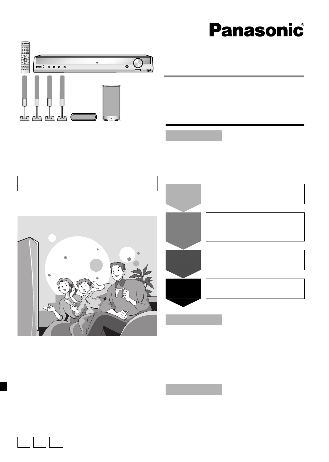
SC-HT17 for continental Europe and the United Kingdom
%DIGITAL
VOLUME
H. BASS
UP
DOWN
PHONES
Dear customer
Thank you for purchasing this product.
Before connecting, operating or adjusting this product, please
read the instructions completely.
Please keep this manual for future reference.
SC-HT17 for continental Europe and the United Kingdom is
used in the illustrations unless otherwise mentioned.
Note:
“EB” on the packaging indicates the United Kingdom.
Operating Instructions
Home Theater Audio System
Model No. SC-HT17
SC-HT15
Table of contents
Before use
Caution for AC Mains Lead ...................................2
Safety precautions.................................................2
Supplied accessories ............................................3
The remote control ................................................ 3
Step 1
Step 2
Speaker setup
4
Home theater
connections
8
Step 3
Step 4
Other connections
10
Settings
13
Operations
Basic operations..................................................15
Control guide........................................................16
The radio............................................................... 18
Other functions ....................................................20
Making a recording ..............................................22
The RESET function ............................................22
Remote control operation guide.........................23
Reference
Troubleshooting guide ........................................ 26
Maintenance ........................................................26
Specifications ......................................................27
EP EB GN
RQT7953-1B
Page 2
Caution for AC Mains Lead
Safety precautions
(For United Kingdom)
(“EB” area code model only)
For your safety, please read the following text carefully.
This appliance is supplied with a moulded three pin mains plug
for your safety and convenience.
A 5-ampere fuse is fitted in this plug.
Should the fuse need to be replaced please ensure that the
replacement fuse has a rating of 5-ampere and that it is
approved by ASTA or BSI to BS1362.
Check for the ASTA mark or the BSI mark on the body of
the fuse.
If the plug contains a removable fuse cover you must ensure that
Before use
it is refitted when the fuse is replaced.
If you lose the fuse cover the plug must not be used until a
replacement cover is obtained.
A replacement fuse cover can be purchased from your local dealer.
CAUTION!
IF THE FITTED MOULDED PLUG IS UNSUITABLE FOR
THE SOCKET OUTLET IN YOUR HOME THEN THE FUSE
SHOULD BE REMOVED AND THE PLUG CUT OFF AND
DISPOSED OF SAFELY.
THERE IS A DANGER OF SEVERE ELECTRICAL SHOCK
IF THE CUT OFF PLUG IS INSERTED INTO ANY 13AMPERE SOCKET.
If a new plug is to be fitted please observe the wiring code as
stated below.
If in any doubt please consult a qualified electrician.
IMPORTANT
The wires in this mains lead are coloured in accordance with the
following code:
Blue: Neutral, Brown: Live.
As these colours may not correspond with the coloured markings
identifying the terminals in your plug, proceed as follows:
The wire which is coloured Blue must be connected to the terminal
which is marked with the letter N or coloured Black or Blue.
The wire which is coloured Brown must be connected to the
terminal which is marked with the letter L or coloured Brown or Red.
WARNING: DO NOT CONNECT EITHER WIRE TO THE
EARTH TERMINAL WHICH IS MARKED WITH THE
LETTER E, BY THE EARTH SYMBOL OR
COLOURED GREEN OR GREEN/YELLOW.
THIS PLUG IS NOT WATERPROOF–KEEP DRY.
Before use
Remove the connector cover.
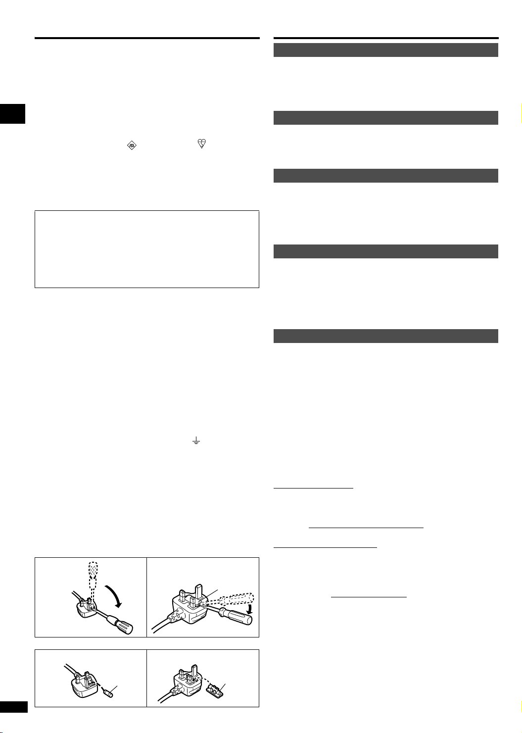
How to replace the fuse
The location of the fuse differ according to the type of AC mains
plug (figures A and B). Confirm the AC mains plug fitted and
follow the instructions below.
Illustrations may differ from actual AC mains plug.
1. Open the fuse cover with a screwdriver.
Figure A
2. Replace the fuse and close or attach the fuse cover.
Figure A Figure B
Fuse
(5 ampere)
RQT7953
2
Figure B
Fuse cover
Fuse
(5 ampere)
Placement
Set the unit up on an even surface away from direct sunlight, high
temperatures, high humidity, and excessive vibration. These conditions
can damage the cabinet and other components, thereby shortening the
unit’s service life.
Do not place heavy items on the unit.
Volt age
Do not use high voltage power sources. This can overload the unit and
cause a fire.
Do not use a DC power source. Check the source carefully when
setting the unit up on a ship or other place where DC is used.
AC mains lead protection
Ensure the AC mains lead is connected correctly and not damaged.
Poor connection and lead damage can cause fire or electric shock. Do not
pull, bend, or place heavy items on the lead.
Grasp the plug firmly when unplugging the lead. Pulling the AC mains
lead can cause electric shock.
Do not handle the plug with wet hands. This can cause electric shock.
Foreign matter
Do not let metal objects fall inside the unit. This can cause electric
shock or malfunction.
Do not let liquids get into the unit. This can cause electric shock or
malfunction. If this occurs, immediately disconnect the unit from the power
supply and contact your dealer.
Do not spray insecticides onto or into the unit. They contain flammable
gases which can ignite if sprayed into the unit.
Service
Do not attempt to repair this unit by yourself. If sound is interrupted,
indicators fail to light, smoke appears, or any other problem that is not
covered in these operating instructions occurs, disconnect the AC mains
lead and contact your dealer or an authorized service center. Electric
shock or damage to the unit can occur if the unit is repaired, disassembled
or reconstructed by unqualified persons.
Extend operating life by disconnecting the unit from the power source if it
is not to be used for a long time.
n Sales and Support Information
(For the United Kingdom and the Republic of Ireland)
Customer Care Centre
• For UK customers: 08705 357357
• For the Republic of Ireland customers: 01 289 8333
• Visit our website for product information
• E-mail: [email protected]
Direct Sales at Panasonic UK
• Order accessory and consumable items for your product with
ease and confidence by phoning our Customer Care Centre
Monday-Friday 9:00am-5:30pm. (Excluding public holidays)
• Or go on line through our Internet Accessory ordering
application at www.panasonic.co.uk
• Most major credit and debit cards accepted.
• All enquiries transactions and distribution facilities are
provided directly by Panasonic UK Ltd.
• It couldn’t be simpler!
• Also available through our Internet is direct shopping for a
wide range of finished products, take a browse on our website
for further details.
Page 3
Supplied accessories
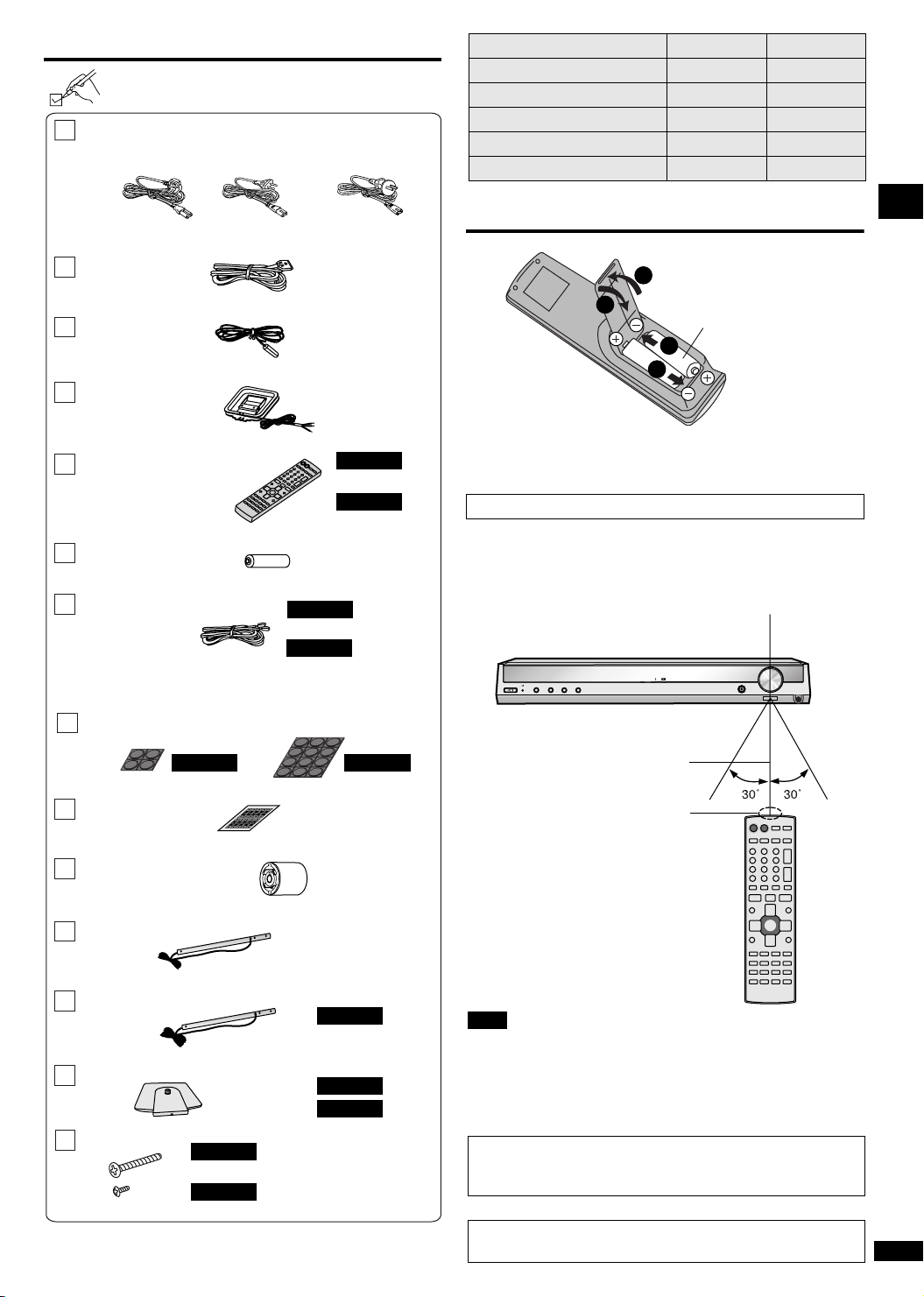
Please check and identify the supplied
accessories.
AC mains lead
For the United
Kingdom
For continental
Europe
For Australia and
New Zealand
System SC-HT17 SC-HT15
Main unit SA-HT17 SA-HT15
Front speakers SB-FS930 SB-FS880
Surround speakers SB-FS880 SB-FS15
Center speaker SB-PC930 SB-PC15
Subwoofer SB-WA17 SB-WA15
(RJA0053-3X) (K2CJ2DA00010)
System cable
FM indoor antenna
(RJA0019-2X)
(K1HA25HA0001)
(RSA0007-L)
AM loop antenna
(N1DAAAA00002)
Remote control transmitter
SC-HT17
(EUR7722KL0)
SC-HT15
(EUR7722KJ0)
Batteries
Speaker cable(s)
(x 2)
SC-HT17
(REE1203A) (4 m x 1)
SC-HT15
(REE1203A) (4 m x 1)
(REE1203C) (10 m x 2)
Rubber pads
(RKA0072-KJ)
The remote control
1
3
• Insert so the poles (+ and –) match those in the remote
control.
• Do not use rechargeable type batteries.
Use
Aim at the sensor, avoiding obstacles, at a maximum range of
7 m directly in front of the unit.
INPUT SELECTOR
2
MENU
2
TUNE
%DIGITAL
R6/LR6, AA, UM-3
2
2
Remote control signal sensor
%PL
VOLUME
H. BASS
UP
DOWN
PHONES
Before use
SC-HT17 SC-HT15
5
4
3
2
1
xxx
xxx
xxx
xxx
Sticker sheet
Antenna plug adapter
(For the United Kingdom)
Speaker stands
xxx
xxxxxx
xxxxxx
xxxxxx
xxxxxx
xxxxxx
xxxxxx
xxxxxx
xxxxxx
xxxxxx
xxxxxx
xxx
xxx
xxx
xxx
xxx
5
4
3
2
1
5
4
3
2
1
xxx
xxx
xxx
xxx
xxx
xxxxxx
xxxxxx
xxxxxx
xxxxxx
xxxxxx
xxxxxx
xxxxxx
xxxxxx
xxxxxx
xxxxxx
xxx
xxx
xxx
xxx
xxx
5
4
3
2
1
(RQCA1029)
(K1YZ02000013)
(RYQV0060)
(x 2)
Speaker stands with long cables
SC-HT17
(RYQV0060A)
(x 2)
Stand bases
(x 4)
(x 2)
(Large x 8)
(Small x 8)
(Large x 4)
(Small x 4)
Screws
(RYQV0059-S)
SC-HT17
SC-HT15
SC-HT17
SC-HT15
(XTN5+32FFN)
(XTN4+8FFN)
(XTN5+32FFN)
(XTN4+8FFN)
Use the numbers indicated in parentheses when asking for
replacement parts. (As of February 2005)
7 meters
Transmission window
Note
• Keep the transmission window and the unit’s sensor free from
dust.
• Operation can be affected by strong light sources, such as
direct sunlight, and the glass doors on cabinets.
Manufactured under license from Dolby Laboratories.
“Dolby”, “Pro Logic” and the double-D symbol are trademarks
of Dolby Laboratories.
“DTS” and “DTS Digital Surround” are registered trademarks
of Digital Theater Systems, Inc.
RQT7953
3
Page 4
Step
1
Speaker setup
Supplied
accessories
Speaker stands with long cables
SC-HT17
Speaker stands
(x 2)
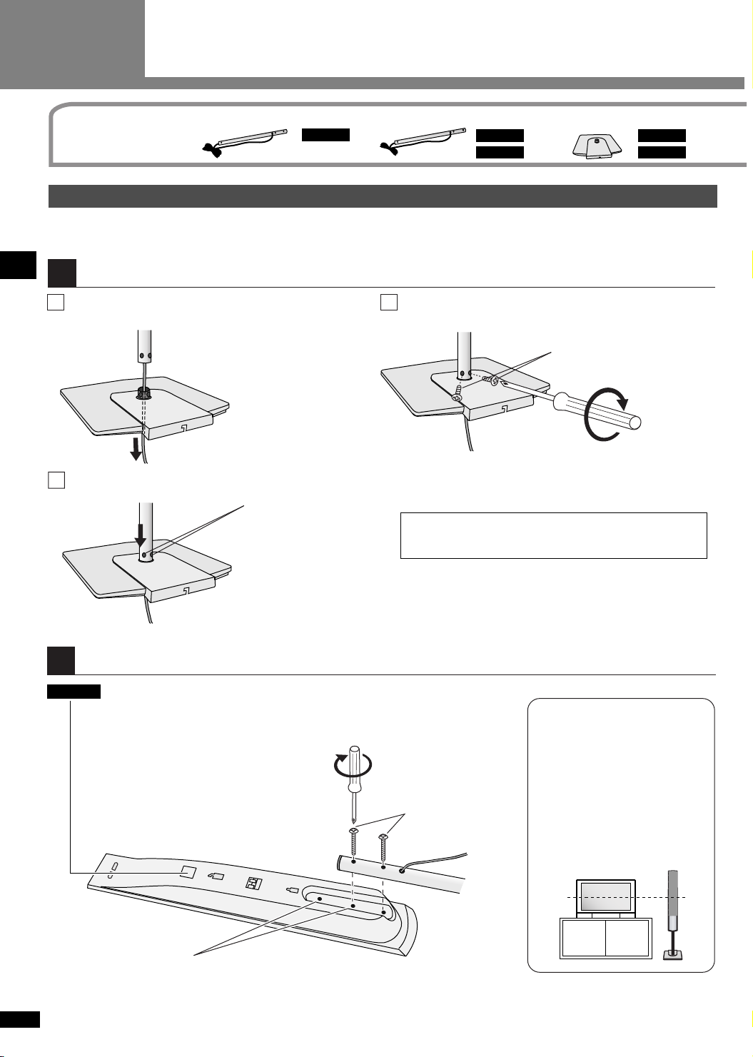
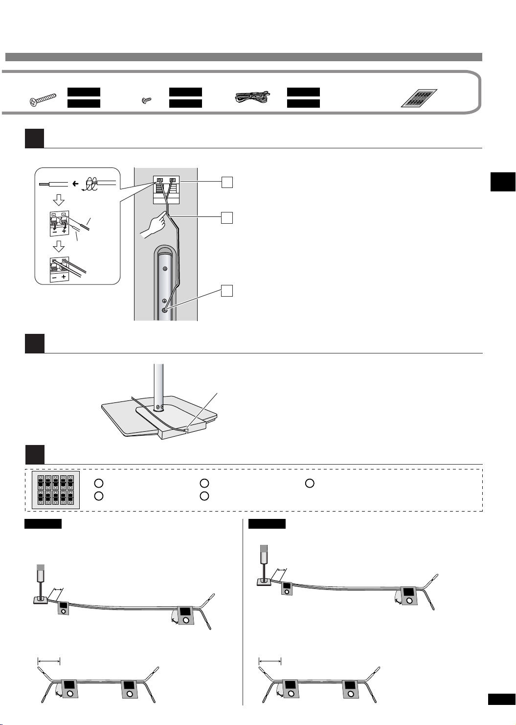
Front and surround speaker assembly
• To prevent damage or scratches, lay a soft cloth and perform assembly on it.
• For assembly, use a Phillips-head screwdriver.
Attach the pipe to the base.
1
Thread the speaker cable through the base.
1
• Untie the cable before threading.
Speaker setup Step 1
Insert the pipe.
2
Match the holes.
3
Ensure the screws are securely fastened by lightly tightening
the left and right side screws alternately until fully tightened.
Stand bases
SC-HT17
SC-HT15
Secure the pipe to the base.
The supplied stands are specially designed for use with
this unit’s speakers.
Only use as indicated in this setup.
(x 2)
SC-HT17
SC-HT15
Small screws
(included)
(x 4)
(x 2)(x 2)
Attach the stand to the speaker.
2
SC-HT17
You can also attach to the upper rear of the speaker.
Ensure the stand is fastened on straight by lightly tightening the top and bottom
RQT7953
screws alternately until fully tightened.
• There is no difference between the right and left speakers.
4
Before attaching, check the speaker label.
• SB-FS930: Use as front speakers. Attach the stands with the short cables.
• SB-FS880: Use as surround speakers. Attach the stands with the long cables.
Large screws
(included)
Speaker height
Front Speakers
Try to line up the middle of the
speakers with the middle of the
television.
Surround speakers
It is usually better to position the
surround speakers a little higher.
Page 5
Large screws
SC-HT17
SC-HT15
Connect the speaker cables.
3
(x 8)
(x 4)
Small screws
SC-HT17
SC-HT15
Speaker cable(s)
(x 8)
(x 4)
Connect the speaker cables.
1
SC-HT17
SC-HT15
(4 m x 1)
(4 m x 1) (10 m x 2)
Sticker sheet
4
3
2
1
xxx
xxx
xxx
xxx
xxxxxx
xxxxxx
xxxxxx
xxxxxx
xxxxxx
xxxxxx
xxxxxx
xxxxxx
xxxxxx
xxx
xxx
xxx
xxx
xxx
5
4
3
2
1
5
4
3
2
1
xxx
xxx
xxx
xxx
xxx
xxxxxx
xxxxxx
xxxxxx
xxxxxx
xxxxxx
xxxxxx
xxxxxx
xxxxxx
xxxxxx
xxxxxx
xxx
xxx
xxx
xxx
xxx
5
4
3
2
1
5
xxx
xxxxxx
(x 1)
Copper
Silver
Fasten the speaker cable to the base.
4
Attach the stickers to the speaker cables.
5
5
4
3
2
1
xxx
xxxxxx
xxxxxx
xxx
1
1
xxx
xxxxxx
xxxxxx
xxx
1
xxx
xxx
xxx
xxx
xxxxxx
xxxxxx
xxxxxx
xxxxxx
xxxxxx
xxxxxx
xxxxxx
xxxxxx
xxx
xxx
xxx
xxx
4
3
2
4
3
2
xxx
xxx
xxx
xxxxxx
xxxxxx
xxxxxx
xxxxxx
xxxxxx
xxxxxx
xxx
xxx
xxx
4
3
2
1
5
5
xxx
xxxxxx
xxxxxx
xxx
5
Front speaker (L)
2
Front speaker (R)
Press the speaker cable into the groove.
2
Thread the excess cable.
3
Slot
3
Surround speaker (L)
Surround speaker (R)
4
Center speaker
5
Speaker setup Step 1
SC-HT17
Front and surround speakers
Use the speakers with long cables for the surround
speakers (SB-FS880).
About 10 cm
FRONT
Lch
1
FRONT
Lch
1
Center speaker
About 10 cm
CENTER
5
CENTER
5
SC-HT15
Front speakers
About 10 cm
FRONT
Lch
1
Surround and center speakers
Use the long speaker cables for the surround
speakers (SB-FS15).
About 10 cm
SURROUND
Lch
3
SURROUND
Lch
3
FRONT
Lch
1
RQT7953
5
Page 6
Supplied
Speaker setup
accessories
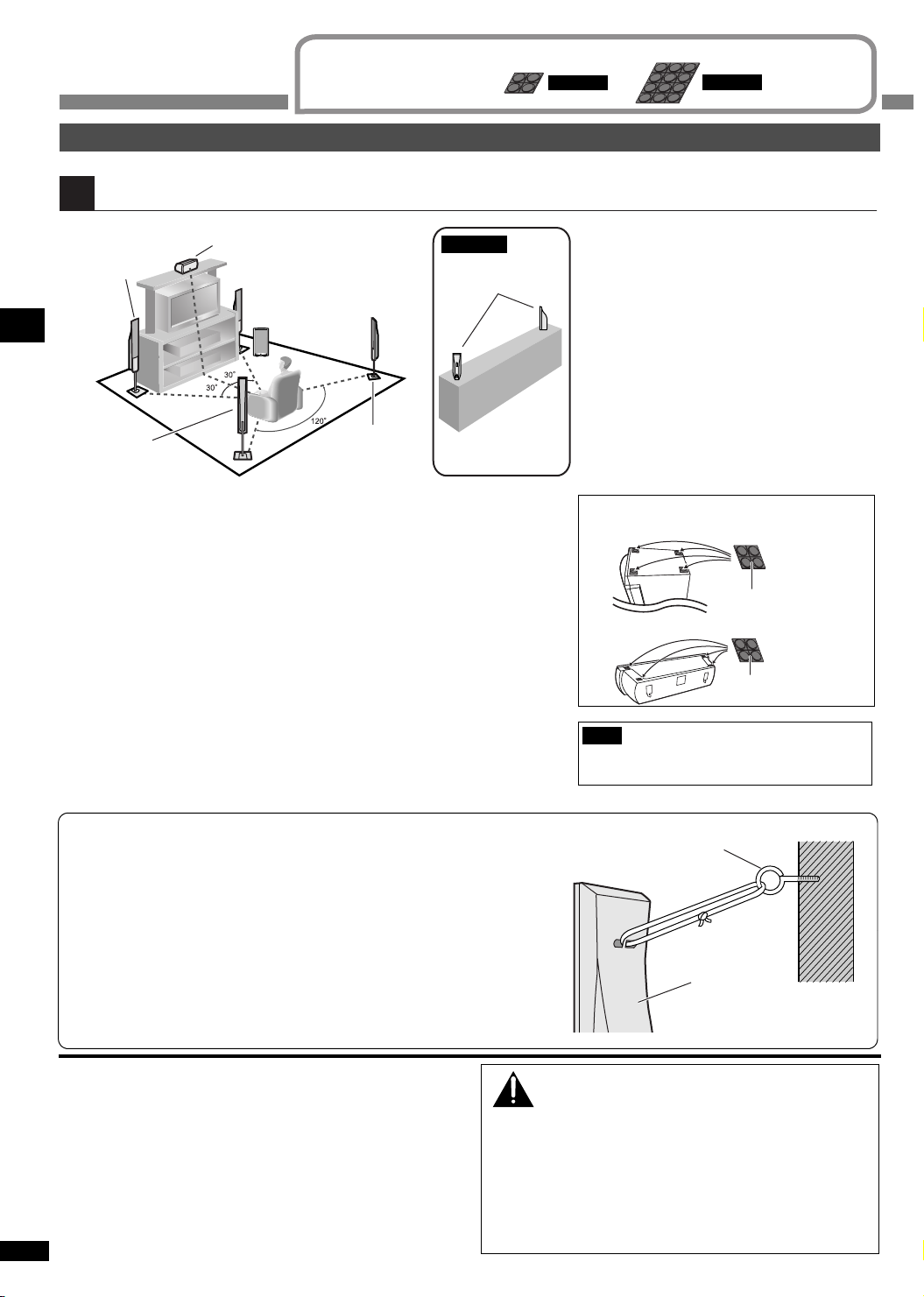
Placement and connections of speakers
Place the speakers.
1
e.g., SC-HT17
Front
speaker (L)
Surround speaker
Speaker setup Step 1
Place the front, center, and surround speakers at approximately the same distance
from the seating position.
The angles in the diagram are approximate.
Center speaker
Front speaker (R)
Subwoofer
Surround
speaker (R)
(L)
SC-HT15
Surround speakers
Place on a shelf or
rack.
Rubber pads
SC-HT17
Positioning for best effect
How you set up your speakers can affect the
bass and the sound field.
Note the following points.
• Attach the included rubber pads to the base
of the center speaker (SC-HT15: center and
surround speakers). This prevents vibration
from causing the speakers to move or fall
over. Use 4 pads per speaker.
• Place speakers on flat secure bases.
• Placing speakers too close to floors, walls,
and corners can result in excessive bass.
Cover walls and windows with a thick
curtain.
Attaching the rubber pads
Bottom of surround speaker (SC-HT15)
SC-HT15
Front speakers (left, right)
Place on the left and right of the TV at seated ear height so that there is good
coherency between the picture and sound.
Center speaker
Place underneath or above the center of the TV. Aim the speaker at the seating
area.
Surround speakers (left, right)
Place on the side of or slightly behind the seating area, higher than ear level.
Subwoofer
The subwoofer can be placed in any position as long as it is at a reasonable
distance from the TV.
Note that some experimentation can yield the smoothest low frequency
performance. Placement near a corner can increase the apparent output level, but
can result in unnatural bass.
Preventing the speakers from falling over
Attach screw eyes (not included) to secure the speakers to a wall
(diagram on the right).
• Obtain the screws appropriate to the walls and pillars to which they are
going to be fastened.
• Consult with a qualified housing contractor concerning the appropriate
procedure when attaching to a concrete wall or a surface that may not
have strong enough support. Improper installation may result in
damage to the wall or speakers.
Rubber pads
Bottom of center speaker
Rubber pads
Note
Keep your speakers at least 10 mm away from
the system for proper ventilation.
screw eyes
(not included)
Speaker
Wall
If irregular colouring occurs on your television
The supplied speakers are designed to be used close to a
television, but the picture may be affected with some televisions
and setup combinations.
If this occurs, turn the television off for about 30 minutes.
The television's demagnetising function should correct the
problem. If it persists, move the speakers further away from the
television.
RQT7953
6
Caution
• The main unit and supplied speakers are only to be
used as indicated in this manual. Failure to do so may
lead to damage to the receiver and/or the speakers,
and may result in the risk or fire. Consult a qualified
service person if damage has occurred or if you
experience a sudden change in performance.
• Do not attempt to attach these speakers to walls using
methods other than those described in this manual.
Page 7
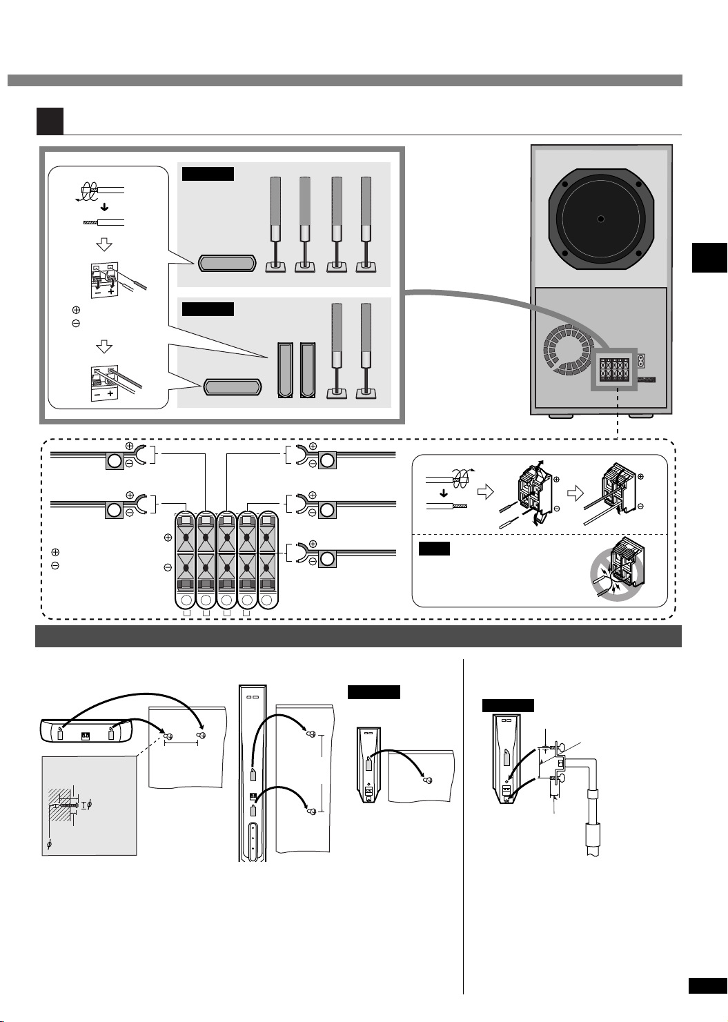
Connect the speaker cables to the subwoofer.
2
SC-HT17
Subwoofer
Copper
SC-HT15
Silver
FRONT (L)
FRONT (R)
1
6 Ω
2
FRONT
Copper
Silver
2 1 4 3 5
R L R L
Other speaker setup options
Attaching to a wall
180 mm
30 - 35 mm
7.5 - 9.4 mm
7 - 9 mm
3.0 - 4.0 mm
Wall or pillar
Screw
(not included)
4 Ω
SURROUND
4 Ω
CENTER
174 mm
4
SURROUND
(R)
3
SURROUND
(L)
5
CENTER
SC-HT15
Surround speakers
Note
Never short-circuit positive (+)
and negative (–) speaker wires.
Fitting optional speaker stands
SC-HT15
Plate thickness +7 to 10 mm
Surround speakers
5 mm, Pitch 0.8 mm
Speaker setup Step 1
60 mm
Speaker
stands (not
included)
• The wall or pillar on which the speakers are to be attached should be capable of
supporting 10 kg per screw. Consult a qualified building contractor when attaching
the speakers to wall. Improper attachment may result in damage to the wall and
speakers.
• When mounting the speakers to walls, use a string (not included) to prevent them
from falling (
è page 6).
• (SC-HT17 front and surround speakers, SC-HT15 front speakers) Use of optional
speaker cables are recommended when mounting. (You can also remove the
speaker cables from the pipes supplied with this system.)
• Observe the diameter and length of the
screws and the distance between screws
as shown in the diagram.
• The stands must be able to support over
10 kg.
• The stands must be stable even if the
speakers are in a high position.
RQT7953
7
Page 8
A
Step
2
Home theater connections
Other
accessories
Stereo phono cable
(not included)
Left
Right
Coaxial cable
(not included)
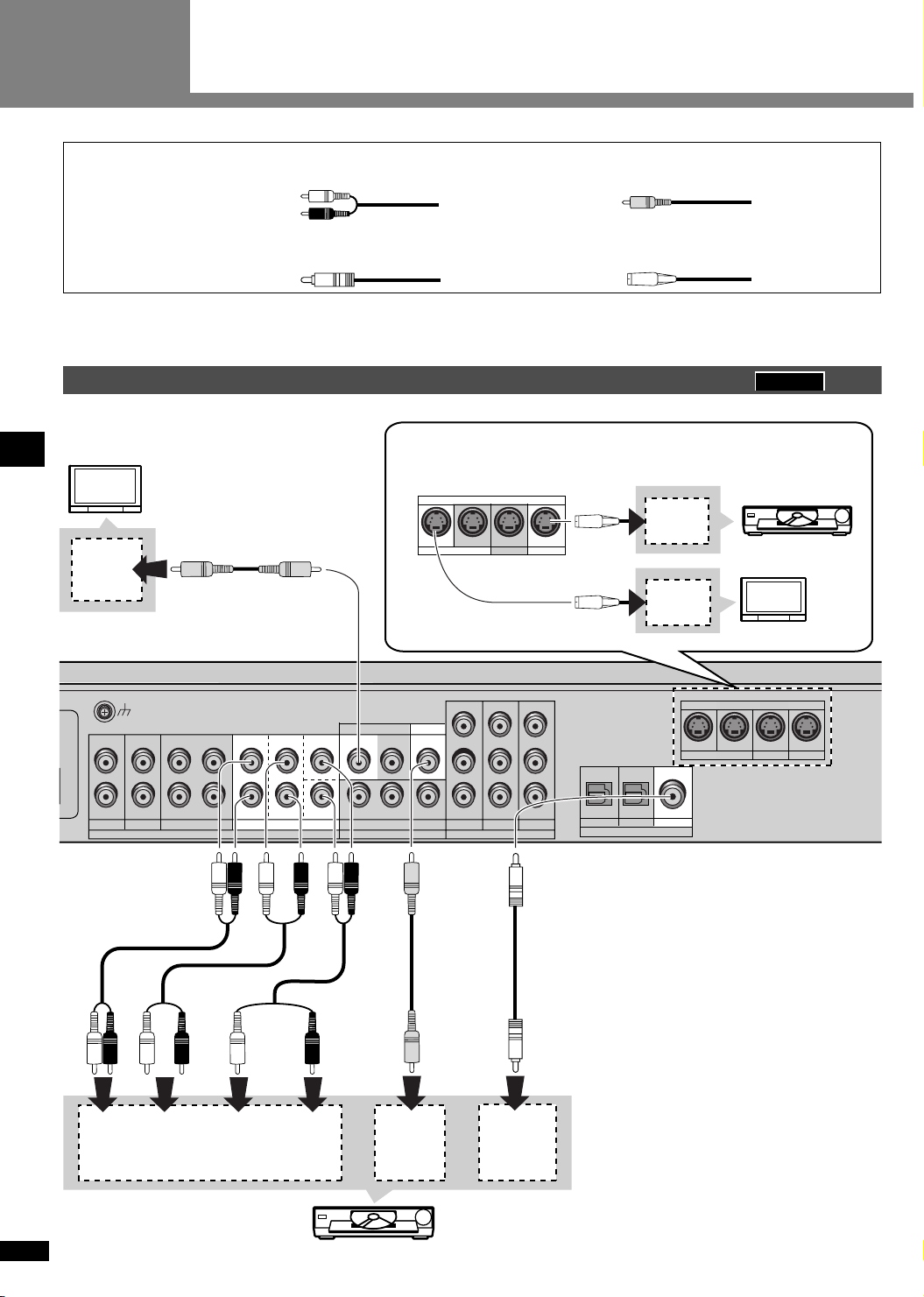
Turn off all components before making any connections.
To connect equipment, refer to the appropriate operating instructions.
DVD player
TV (Monitor)
VIDEO
IN
S-VIDEO terminals
Use this connection for better picture quality than with the VIDEO
terminals.
S-VIDEO
MONITOR OUT
IN IN IN
TV
DVR / VCR
Video connection cable
(not included)
S-Video cable
(not included)
SC-HT17
S-VIDEO
OUT
DVD
S-VIDEO
IN
TV (Monitor)
Home theater connections Step 2
LOOP
ANT
FM
NT
AM
ANT
GND
L L L L L L
R R R R R R
IN
GAME/AUX
FRONT
(L, R)
OUTIN
DVR / VCR
TV DVD / DVD 6CH
SURROUND
FRONT
SURROUND
AUDIO VIDEO
SUBWOOFER
(L, R)
CENTER
SUBWOOFER
CENTER
AUDIO OUT
TV
IN
MONITOR OUT
OUT ININ IN
DVR / VCR
VIDEO
OUT
DVD
IN
GAME/AUX
P
B
PR PR P
TV MONITOR
COMPONENT VIDEO
PB P
DVR TV
DIGITAL
AUDIO
OUT
Y Y Y
B
R
INOUT IN
(TV) IN (DVR) IN (DVD) IN
OPT 1 OPT 2
DIGITAL IN
MONITOR OUT
COAXIAL
S-VIDEO
IN IN IN
TV
DVR / VCR
DVD
RQT7953
DVD Player
8
Page 9
M
Supplied
accessories
System cable AC mains lead
(x 1)
or
or
(x 1)
Changing the digital input settings
You can change the input settings for the digital terminals if
necessary. Note the equipment you have connected to the
terminals, then change the settings (
Note
è page 13).
• The included AC mains lead is for use with this unit only. Do
not use it with other equipment.
• Do not use an AC mains lead from any other type of
equipment with this unit.
• Use digital connection to enjoy Dolby Digital or DTS.
DVD player
LOOP
ANT
L
GAME/AUX
GND
L R L R L
OUTININ IN
DVR / VCRTV
AUDIO
L
R R
R
IN
DVD
FRONT (L, R)
AUDIO OUT
FM
ANT
AM
ANT
Notes on digital input
This unit can decode the following signals:
• Dolby Digital, DTS
• PCM, including PCM with sampling frequencies of 96
or 88.2 kHz
It cannot decode:
• Other digital signals, such as MPEG
• Dolby Digital RF signals from a laser disc player
(TV) IN (DVR) IN (DVD) IN
DIGITAL AUDIO
OUT
OPT 1 OPT 2
VIDEO
OUT
COAXIAL
DIGITAL IN
Connect the video
cable directly to the TV.
SC-HT15
VIDEO IN
Home theater connections Step 2
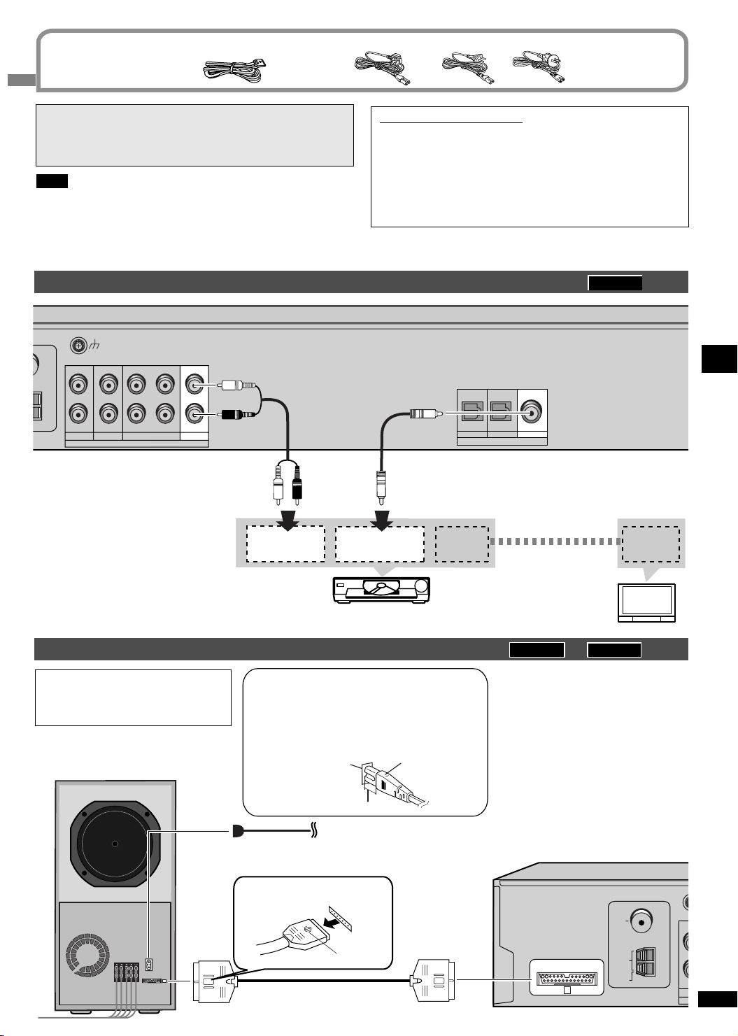
Subwoofer and AC mains lead
FOR THE UNITED KINGDOM ONLY
READ THE CAUTION FOR THE AC
MAINS LEAD ON PAGE 2 BEFORE
CONNECTION.
Subwoofer
AC IN
~
A
To SA-HT17
DVD player
Insertion of connector
Even when the connector is perfectly inserted,
depending on the type of inlet used, the front
part of the connector may jut out as shown in
the drawing. However there is no problem using
the unit.
Appliance inlet
Approx. 6 mm
è To household AC mains socket
AC mains lead (included)
Connect this cord after all other cables are connected.
To disconnect
Press the catch and pull out.
Catch
System cable (included)
Connector
TV (Monitor)
SC-HT17
Conserving power
The unit consumes a small amount
of power even when it is turned off
with [8]. To save power when the
unit is not to be used for a long time,
unplug it from the household AC
mains socket. You will need to reset
some memory items after plugging in
the unit.
TO SB-WA17
A
SC-HT15
75 Ω
LOOP
EXT
FM
ANT
AM
ANT
L
R
RQT7953
GA
9
Page 10
Step
3
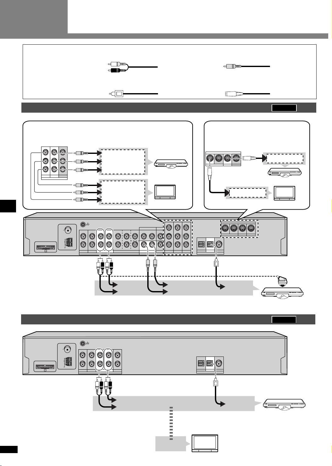
Other connections
Other
accessories
Stereo phono cable
(not included)
Left
Right
Optical fibre cable
(not included)
DVD recorder or VCR
COMPONENT VIDEO terminals
This connection provides high quality pictures by separating the colour
(P
B and PR) and the luminance (Y) signals.
PB P
P
B
PR PR P
TV MONITOR
DVR TV
COMPONENT VIDEO
TO SB-WA17
A
75 Ω
LOOP
Y Y Y
B
R
INOUT IN
FM
ANT
L L L L L L
R R R R R R
AM
ANT
EXT
IN
GAME/AUX
Y
COMPONENT
P
B
VIDEO OUT
P
R
P
R
COMPONENT
P
B
VIDEO IN
Y
LOOP
ANT
GND
OUTIN
DVR / VCR
TV DVD / DVD 6CH
SURROUND
FRONT
AUDIO VIDEO
CENTER
SUBWOOFER
TV (Monitor)
TV
IN
MONITOR OUT
OUT ININ IN
DVR / VCR
DVD
GAME/AUX
IN
PB P
P
B
PR PR P
TV MONITOR
COMPONENT VIDEO
DVR TV
Y Y Y
B
R
INOUT IN
Video connection cable
(not included)
S-Video cable
(not included)
SC-HT17
S-VIDEO terminals
Use this connection for better picture quality
than with the VIDEO terminals.
S-VIDEO
MONITOR OUT
TV
IN IN IN
DVR / VCR
DVD
S-VIDEO OUT
S-VIDEO IN
TV (Monitor)
S-VIDEO
MONITOR OUT
IN IN IN
DVR / VCR
DVD
(TV) IN (DVR) IN (DVD) IN
OPT 1 OPT 2
COAXIAL
DIGITAL IN
TV
Other connections Step 3
RQT7953
10
DVD recorder or VCR
FM
75 Ω
ANT
L R L R L
L
AM
LOOP
TO SB-WA15
A
ANT
EXT
GAME/AUX
LOOP
ANT
GND
OUTININ IN
DVR / VCRTV
AUDIO
R R
AUDIO OUT
AUDIO IN
L
R
IN
DVD
AUDIO OUT
AUDIO IN
VIDEO OUT
VIDEO IN
(TV) IN (DVR) IN (DVD) IN
OPT 1 OPT 2
DIGITAL IN
VIDEO OUT
Connect the video cable directly
to the TV.
VIDEO IN
21-pin scart cable connection
also possible.
DIGITAL AUDIO
OUT
DVD recorder or VCR
SC-HT15
COAXIAL
DVD recorder or V CR
DIGITAL AUDIO
OUT
TV (Monitor)
Page 11
Changing the digital input settings
You can change the input settings for the digital terminals if
necessary. Note the equipment you have connected to the
terminals, then change the settings (
è page 13).
Note
• Use digital connection to enjoy Dolby Digital or DTS.
• Do not bend the optical fibre cable.
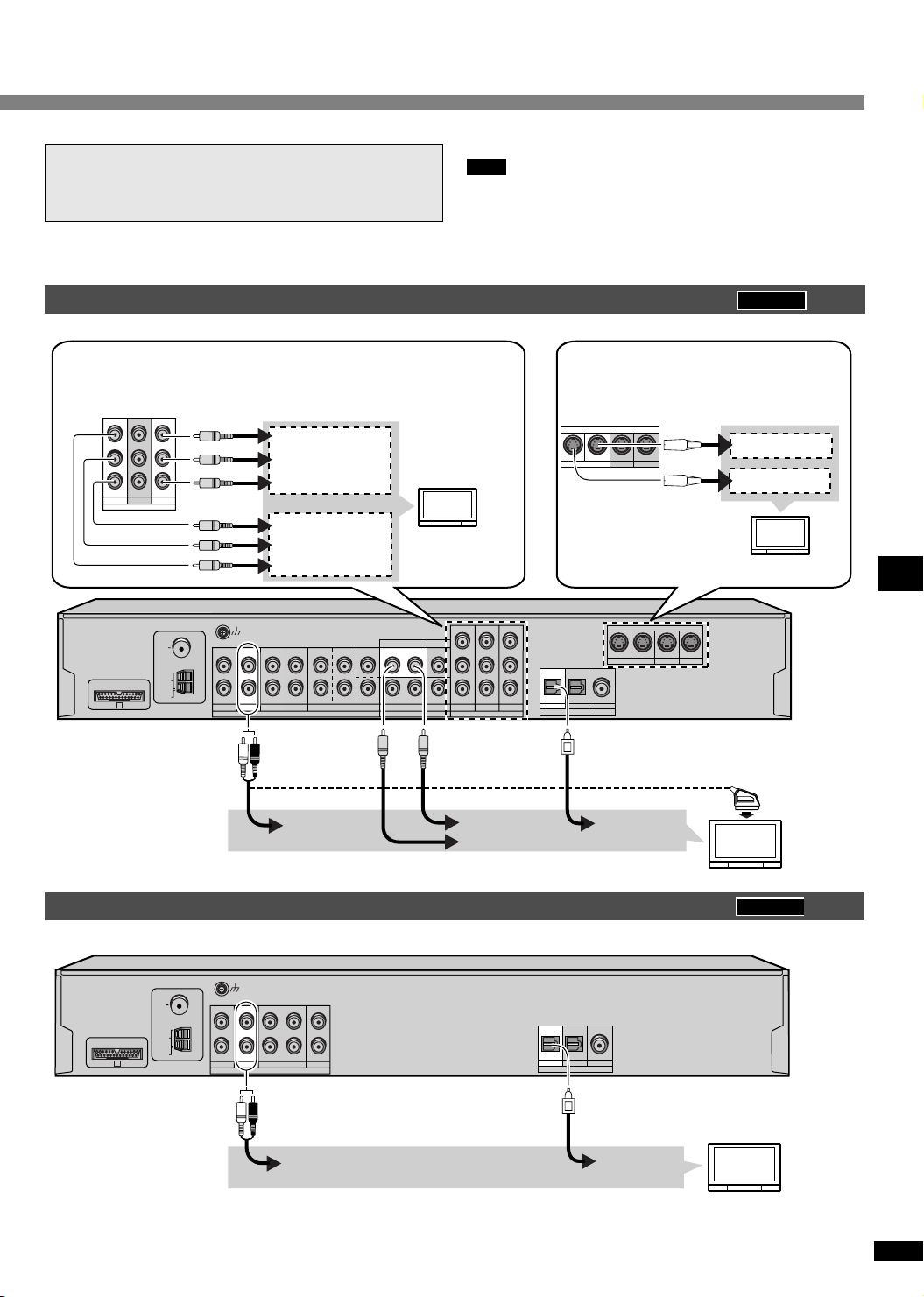
TV (Input source)
COMPONENT VIDEO terminals
This connection provides high quality pictures by separating the colour
(P
B and PR) and the luminance (Y) signals.
PB P
P
B
PR PR P
TV MONITOR
DVR TV
COMPONENT VIDEO
TO SB-WA17
A
Y Y Y
75 Ω
LOOP
B
R
INOUT IN
FM
ANT
L L L L L L
R R R R R R
AM
ANT
EXT
GAME/AUX
Y
COMPONENT
P
B
VIDEO OUT
P
R
P
R
COMPONENT
P
B
Y
LOOP
ANT
GND
IN
OUTIN
DVR / VCR
TV DVD / DVD 6CH
AUDIO VIDEO
VIDEO IN
FRONT
SURROUND
SUBWOOFER
CENTER
TV
IN
MONITOR OUT
OUT ININ IN
DVR / VCR
DVD
IN
GAME/AUX
PB P
P
B
PR PR P
TV MONITOR
DVR TV
COMPONENT VIDEO
Y Y Y
B
R
INOUT IN
SC-HT17
S-VIDEO terminals
Use this connection for better picture quality
than with the VIDEO terminals.
S-VIDEO
MONITOR OUT
IN IN IN
TV
DVR / VCR
DVD
S-VIDEO OUT
S-VIDEO IN
S-VIDEO
MONITOR OUT
IN IN IN
DVR / VCR
DVD
(TV) IN (DVR) IN (DVD) IN
OPT 1 OPT 2
COAXIAL
DIGITAL IN
TV
21-pin scart cable connection
also possible.
Other connections Step 3
TV (Input source)
FM
75 Ω
ANT
FM
75 Ω
ANT
AM
LOOP
TO SB-WA15
TO SB-WA15
A
A
LOOP
ANT
AM
EXT
ANT
EXT
L
L
GAME/AUX
GAME/AUX
LOOP
ANT
GND
LOOP
ANT
L R L R L
GND
L R L R L
OUTININ IN
DVR / VCRTV
AUDIO
OUTININ IN
DVR / VCRTV
AUDIO
AUDIO
OUT
R R
R R
AUDIO
OUT
AUDIO
OUT
VIDEO OUT
VIDEO IN
DIGITAL AUDIO
OUT
TV
SC-HT15
L
L
R
R
IN
DVD
IN
DVD
(TV) IN (DVR) IN (DVD) IN
OPT 1 OPT 2
COAXIAL
DIGITAL IN
(TV) IN (DVR) IN (DVD) IN
OPT 1 OPT 2
COAXIAL
DIGITAL IN
DIGITAL AUDIO
OUT
DIGITAL AUDIO
TV
OUT
RQT7953
11
Page 12
R
B
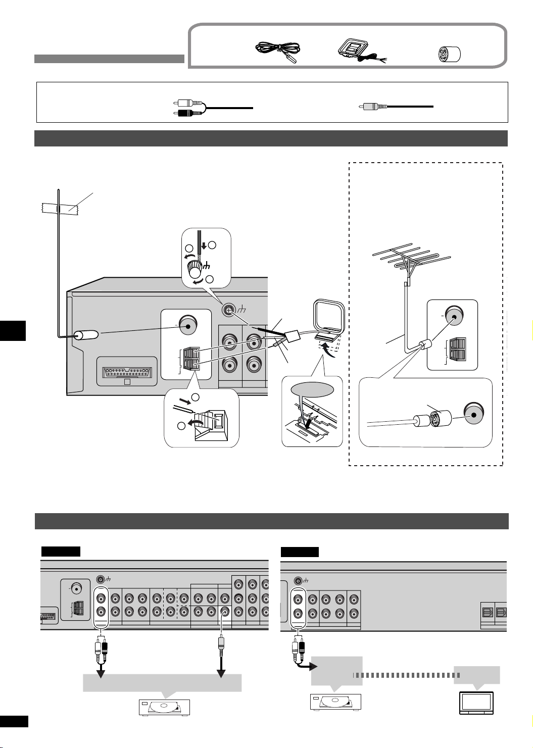
Other connections
A
N
N
A
Supplied
accessories
FM indoor antenna
(x 1)
AM loop antenna Antenna plug adapter
(For the United Kingdom)
(x 1) (x 1)
Other
accessories
Antennas
FM indoor antenna
(included)
Other connections Step 3
Stereo phono cable (not included) Video connection cable (not included)
Left
Right
Adhesive tape
Fix the end of the antenna
where reception is best.
75 Ω
TO SB-WA17
LOOP
EXT
A
1
For best reception
FM outdoor antenna (not included)
• Disconnect the FM indoor antenna.
• The antenna should be installed by a
competent technician.
FM outdoor antenna
2
1
LOOP
ANT
GND
3
FM
ANT
L L L L L L
R R R R R R
AM
ANT
IN
GAME/AUX
2
AM loop antenna
(included)
LOOP
ANT
GND
Black
Red
White
OUTIN
DVR / VCRTV DVD / DVD 6CH
AUDIO VIDEO
Click!
FRONT
75
cable
SURROUND
75 Ω
MONITOR OUT
CENTER
Ω coaxial
TV
DVD
IN
LOOP
EXT
SUBWOOFER
OUT ININ IN
DVR / VCR
For the United Kingdom
GAME/AUX
Antenna plug adaptor
(included)
ANT
IN
P
B
PR PR P
OUT IN
TV MONITOR
COMPONENT VIDE
FM ANT
FM
AM
ANT
75 Ω
Y Y Y
PB P
DVR
Keep the antenna cord away from DVD players and other cords.
Game machine or other AV equipment
SC-HT17
LOOP
ANT
GND
FM
75 Ω
ANT
L L L L L L
R R R R R R
AM
LOOP
-WA17
ANT
EXT
IN
OUTIN
DVR / VCR
TV DVD / DVD 6CH
GAME/AUX
SURROUND
FRONT
AUDIO VIDEO
AUDIO OUT
RQT7953
12
Game machine
CENTER
SUBWOOFER
TV
IN
MONITOR OUT
OUT ININ IN
DVR / VCR
VIDEO OUT
DVD
GAME/AUX
IN
PB P
P
B
PR PR P
TV MONITOR
DVR TV
COMPONENT VIDEO
Y Y Y
B
R
INOUT IN
SC-HT15
FM
NT
L
AM
ANT
GAME/AUX
LOOP
ANT
GND
L R L R L
OUTININ IN
DVR / VCRTV
AUDIO
L
R R
R
IN
DVD
AUDIO OUT
VIDEO OUT
Game machine
Connect the video cable
directly to the TV.
(TV) IN (DVR) I
OPT 1 OPT 2
VIDEO IN
TV (Monitor)
DIGITAL I
Page 13
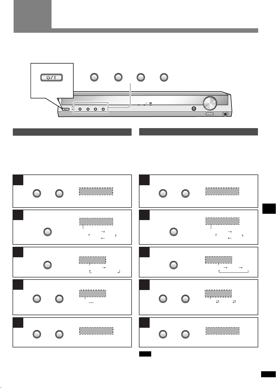
Step
Change the settings to suit your equipment to the environment in which you are using it. Before making any changes, read the
descriptions of the settings, note the factory settings and ranges, and refer to the equipment’s instructions.
DISTANCE è See below
D-INPUT è See below
4
Settings
DR COMP è See page 21
A/D ATT è See page 21
INPUT SELECTOR
2
TUNE
2
MENU
Switch on.
%DIGITAL
2
2
TUNE
INPUT SELECTOR
MENU
DISTANCE
Enter the distance of the front, center and surround speakers
from the seating position.
The factory settings are:
Enter the setup mode. Enter the setup mode.
1
2
TUNE
FRONT:
CENTER:
SURROUND:
2
3.0 m
3.0 m
1.5 m
%PL
D-INPUT (digital input)
Change the setting for the DIGITAL IN terminals (OPT1, OPT2,
COAXIAL) on the rear of the unit if the equipment you have
connected is different to that labelled.
The factory settings are:
1
2
TUNE
SETUP
Press at the same time.
Select “DISTANCE”.
2
INPUT SELECTOR
DISTANCE
DISTANCE
D-INPUT
DR COMP
A/D ATT
Press at the same time.
Select “D-INPUT”.
2
INPUT SELECTOR
H. BASS
TV:
DVR:
DVD:
2
VOLUME
DOWN
OPT1
OPT2
COAX
UP
SETUP
D-INPUT
DISTANCE
D-INPUT
PHONES
DR COMP
A/D ATT
Step 4
Settings
Select the speaker.
3
4
Press at the same time.
MENU
Change the setting.
2
TUNE
OR
Repeat steps 3 and 4
Exit the setup mode.
2
TUNE
2
2
FRONT
FRONT CENTER
SURROUND
3.0 m
1.0 m 10.0 m
COMPLETE
Select the input position.
3
4
55
MENU
Change the setting.
2
TUNE
OR
Repeat steps 3 and 4
Exit the setup mode.
2
TUNE
2
2
TV
TV DVR DVD
OPT 1
OPT 1 OPT 2 COAX
COMPLETE
Press at the same time.
Note
You can allocate only one piece of equipment per terminal. So
for example if you change “TV” from “OPT1” to “OPT2”, “DVR”
will automatically switch to “OPT1”.
RQT7953
13
Page 14
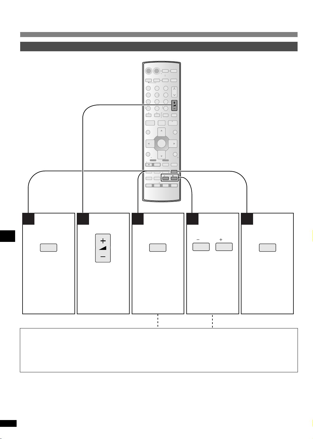
Settings
Adjusting speaker output level
AV SYSTEMRECEIVER
DVD
PLAYER
^^
ANALOG 6CH
DVD
DRIVE
SELECT
1
45 6
7089
DIRECT TUNING
DISC
SKIP
u
STOP PAUSE
gh
DIRECT NAVIGATOR
TOP MENU
SUB MENU/
PLAY LIST
TV VOL TV VOL
DVD REC
REC
INPUT MODE
TONE/
BALANCE
OFF
RECORDER
23
-/--
i
ENTER
REC MODE
-
SUBWOOFER
-
EFFECT
%PL
-
TUNER/
VCR
-
VOLUME
>
10
=
SLOW/SEARCH
t
PLAY
TV
MUTING
TV/AV
H.BASS/
-
C.FOCUS
-
/L /R
SFC
MUSIC
AV/MOVIE
TV
BAND
CH
y
q
FUNCTIONS
RETURN
LEVEL/
TEST
1 2 53 4
VOLUME
-
LEVEL/
-
TEST
Press and hold
Settings Step 4
Output the
signal.
C (center), RS (right surround) and LS (left surround) can be adjusted between –10 dB and +10 dB, with 0 dB being the level of
the front speakers. Adjust center and surround output to the same apparent level of the front speakers.
For SW (subwoofer), you can select “- - -” so there is no output, “MIN” for minimum output, a level between 1 and 19, or “MAX” for
maximum output. Adjust subwoofer output so it is balanced with the front speakers.
Subwoofer output is easily influenced by the source. You can also change its level while playing something for better effect
(
è page 20).
Adjust the main
volume.
-
LEVEL/
-
TEST
Select the
speaker
channel.
/L /R
Adjust the level.
Repeat steps 3 and 4
-
LEVEL/
-
TEST
Press and hold
Stop the test
signal.
14
RQT7953
Page 15
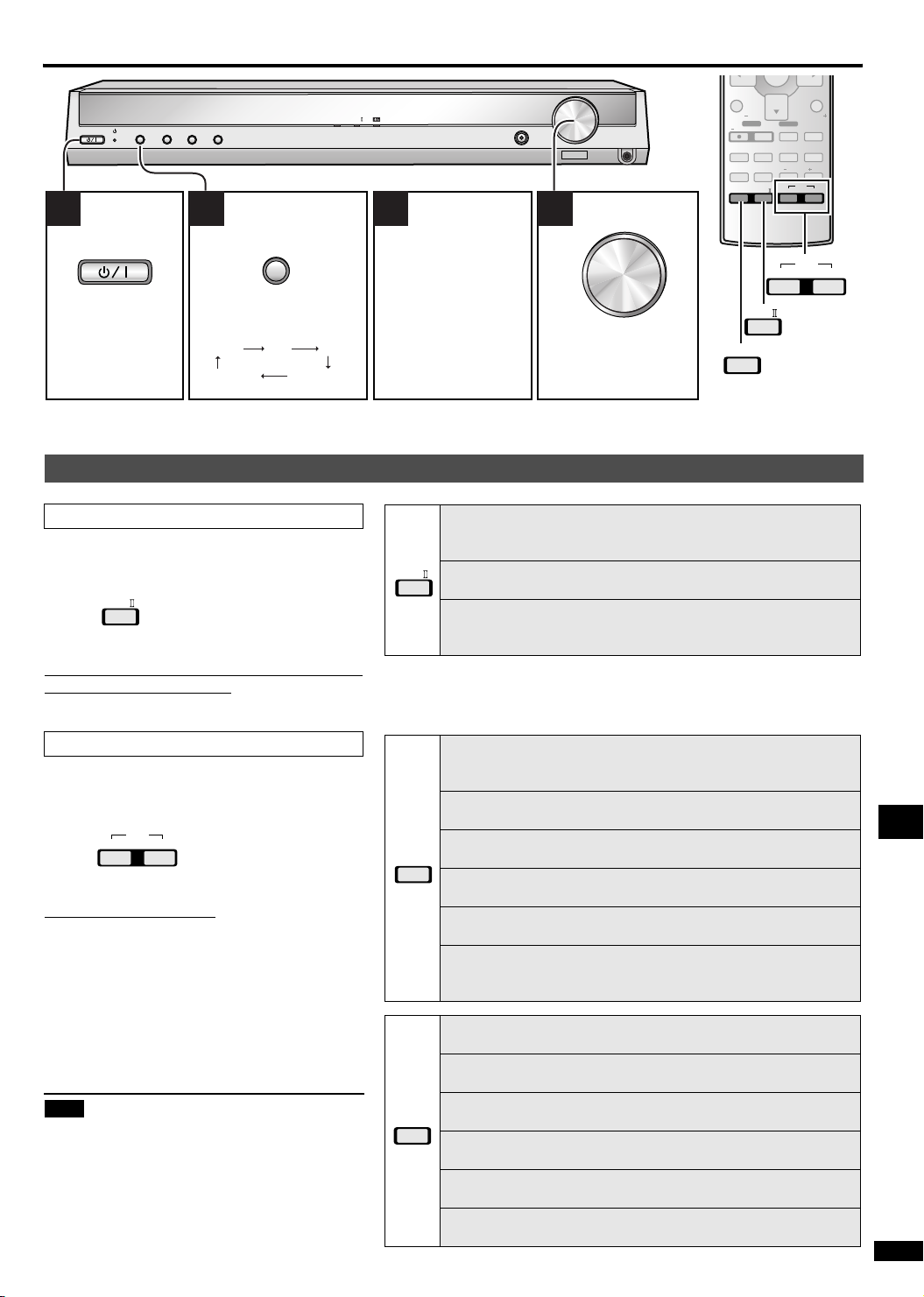
Basic operations
ENTER
%DIGITAL
INPUT SELECTOR
2
2
TUNE
MENU
%PL
H. BASS
1 2 3 4
INPUT SELECTOR
Switch on. Select input.
TUNER TVDVD
DVR/VCRGAME/AUX
(SC-HT17) When playing video sources connected to DVD
The picture remains on the screen even if you select TUNER.
Adding surround effects to stereo sources
Using Dolby Pro LogicII
Dolby Pro LogicII processor works not only on
sources recorded with Dolby Surround, but also on
any stereo source.
%PL
Press to select a mode from the table at right.
• To cancel, press [OFF].
You can make fine surround settings when in the
MUSIC or PANORAMA mode. (è page 22)
Start play of the
source.
The unit sets the
sound mode to suit
the input signal.
MOVIE
Use this mode when playing movie software, especially
videotapes, recorded in Dolby Surround.
MUSIC
%PL
Adds surround effects to stereo sources.
PANORAMA
Sound is spread out more so you feel like you are surrounded by
music.
VOLUME
DOWN
VOLUME
DOWN
Adjust the
volume.
SUB MENU/
PLAY LIST
TV VOL TV VOL
DVD REC
REC MODE
UP
PHONES
UP
REC
INPUT MODE
TONE/
BALANCE
OFF
OFF
SUBWOOFER
%PL
EFFECT
%PL
TV
TV/AV
-
H.BASS/
-
C.FOCUS
/L /R
MUSIC
MUSIC
RETURN
MUTING
-
LEVEL/
-
TEST
SFC
AV/MOVIE
SFC
AV/MOVIE
Using the Sound Field Control (SFC)
Enjoy an enhanced sound experience with greater
presence and spread by using these SFC modes
with PCM or analogue stereo sources.
SFC
AV/MOVIE
MUSIC
Press to select a mode from the tables at right.
• To cancel, press [OFF].
You can adjust SFC effects.
Note
(è page 22)
• Dolby Pro LogicII and SFC modes remain in
effect until you turn the mode off.
• When input is PCM with sampling frequencies of
96 or 88.2 kHz, you cannot add surround effects
with Dolby Pro LogicII or SFC.
• When input is Dolby Digital or DTS, you cannot
use SFC.
LIVE
Brings you up close for “live” stage performance and smoother
vocals.
POP/ROCK
For pop, rock, and other music that has a punch to it.
VOCAL
For adding gloss to vocals.
MUSIC
JAZZ
Conveys the exciting and intimate atmosphere of a jazz club.
DANCE
For dance music and other sounds with a strong beat.
PA RT Y
This mode uses the front and surround speakers so that sound is in
stereo regardless of the direction you are facing.
DRAMA
For dramas and other material where dialog is important.
ACTION
For action movies and other material where impact is important.
SPORTS
To make you feel like you were in the stadium.
AV/MOVIE
MUSICAL
For musicals and other material where music is important.
GAME
Enjoy gaming with more impact.
MONO
For monaural sound.
Operations
RQT7953
15
Page 16
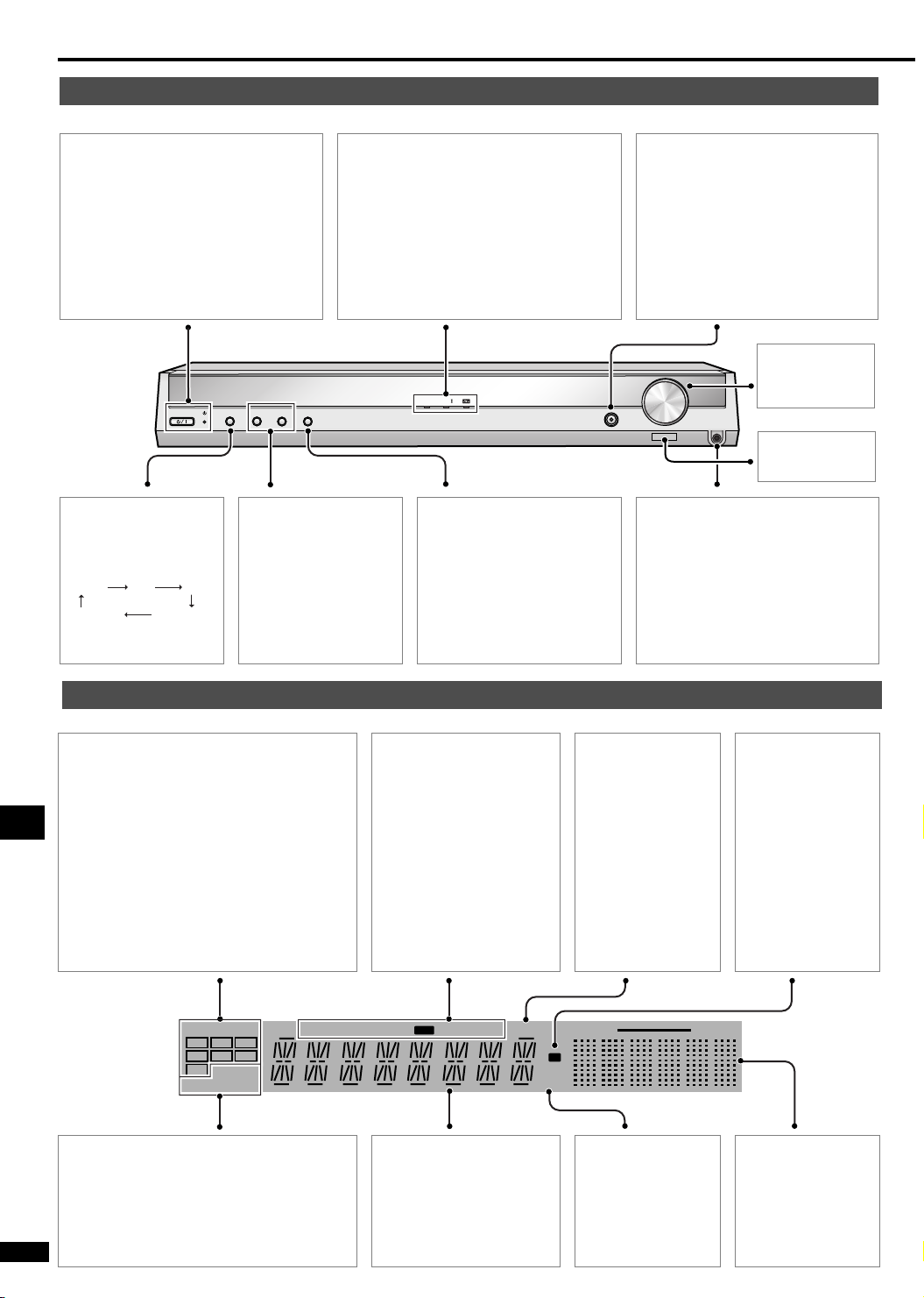
Control guide
Main unit
Standby indicator [^]
When the unit is connected to the AC
mains supply, this indicator lights up in
standby mode and goes out when the
unit is turned on.
Standby/on switch [8]
Press to switch the unit from on to
standby mode or vice versa. In standby
mode, the unit is still consuming a small
amount of power.
2
2
TUNE
MENU
[INPUT SELECTOR]
For selecting input.
The display changes as
follows:
TUNER TVDVD
DVR/VCRGAME/AUX
INPUT SELECTOR
[2 TUNE 1]
For tuning the radio and
presetting channels.
[% DIGITAL, % PL II, dts]
Lights to indicate the source’s input signal
and decoding format used.
% DIGITAL: Dolby Digital sources
% PL II: Dolby Pro LogicII decoder is
being used
dts: DTS sources
%DIGITAL
%PL
H. BASS
[MENU]
• For entering various
settings.
• Press and hold to exit the
MENU mode.
[H.BASS]
For enhancing the bass sound.
The indicator lights when the feature
is on.
[VOLUME]
VOLUME
DOWN
UP
PHONES
Vol u m e contro l .
Remote control
signal sensor
[PHONES]
Headphone jack
Plug type: 3.5 mm stereo
• Sound does not come from the
speakers if you connect
headphones.
• Avoid listening for prolonged
periods of time to prevent hearing
damage.
Display
[DIGITAL INPUT]
Program format indicators
Show the channels contained in the digital
input signal.
They do not light when input is analogue.
L: Front left channel
C: Center channel
R: Front right channel
LS: Surround left channel
S: If the surround channel is monaural
RS: Surround right channel
Operations
LFE (Low Frequency Effects): Deep-bass
effect.
DIGITAL INPUT
C
L
R
S
LS RS
LFE
C.FOCUS
SFC
2CH MIX
[C.FOCUS, 2CH MIX, SFC]
C.FOCUS: Appears when you are using
Center Focus
2CH MIX: Appears when you are listening to a
multi-channel source with headphones
RQT7953
SFC: Appears when you are using an SFC
mode
16
TUNED
[TUNED, ST, MONO]
Radio indicators
TUNED: A station is tuned.
ST: A stereo FM broadcast
is tuned.
MONO: You have switched
to monaural mode to
improve reception.
[RDS, PS, PTY]
(For continental Europe
and the United Kingdom)
Shows the current RDS
display mode.
RDS
MONO PS PTY
ST
General display
Shows the input mode, radio
frequency and other general
information.
SLEEP
[SLEEP]
Sleep timer indicator.
100Hz
M
kHz
MHz
[kHz, MHz]
Frequency unit
indicators
kHz: AM, or PCM
sampling frequency
MHz: FM
[M]
Flashes or lights
during presetting.
10kHz
Spectrum
analyzer display
Page 17
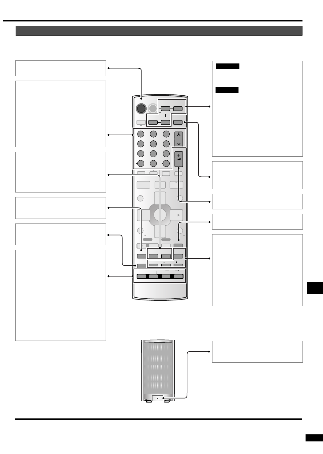
Remote control and Subwoofer
This page describes the buttons used to control this unit.
See the guide starting page 23 for the buttons that control other units.
[^, RECEIVER]
Standby/on button.
[1, 2, 3, 4, 5, 6, 7, 8, 9, 0]
To enter radio frequencies and
channels.
[ ≧ 10, -/--]
To enter two digit channels.
[DISC, DIRECT TUNING]
To enable selection of radio stations
by frequency.
[1, CH, 2]
For selecting preset radio channels.
[SUBWOOFER]
For selecting subwoofer level.
[-H.BASS/–C.FOCUS]
• For enhancing the bass sound.
• Press and hold to select center
focus mode.
[INPUT MODE]
For selecting AUTO, ANALOG or
DIGITAL.
[TONE/BALANCE]
To adjust the bass, treble and front
speaker balance.
[OFF]
To cancel surround effect.
[% PL II]
For selecting a Dolby Pro LogicII
mode: MOVIE, MUSIC or
PANORAMA.
[MUSIC]
For selecting SFC modes: LIVE, POP/
ROCK, VOCAL, JAZZ, DANCE or
PA RT Y .
[AV/MOVIE]
For selecting SFC modes: DRAMA,
ACTION, SPORTS, MUSICAL, GAME
or MONO.
AV SYSTEMRECEIVER
DVD
TV
DVD
RECORDER
23
SKIP
i
ENTER
DVD REC
REC MODE
SUBWOOFER
EFFECT
%PL
PLAYER
ANALOG 6CH
-
TUNER/
VCR
-
BAND
VOLUME
-/--
>
10
=
SLOW/SEARCH
t
PLAY
q
FUNCTIONS
RETURN
TV
MUTING
TV/AV
-
H.BASS/
-
LEVEL/
-
C.FOCUS
-
/L /R
SFC
MUSIC
AV/MOVIE
TEST
^^
DRIVE
SELECT
1
45 6
7089
DIRECT TUNING
DISC
u
STOP PAUSE
gh
DIRECT NAVIGATOR
TOP MENU
SUB MENU/
PLAY LIST
TV VOL TV VOL
REC
INPUT MODE
TONE/
BALANCE
OFF
SC-HT17SC-HT17
[DVD PLAYER, –ANALOG 6CH]
[TV] [DVD RECORDER] [VCR]
SC-HT15
[DVD PLAYER] [TV]
[DVD RECORDER] [VCR]
Input mode and remote control mode
buttons.
[DVD PLAYER, –ANALOG 6CH]
(SC-HT17)
CH
Press and hold and DVD input
switches between 6-channel and
2-channel.
[-TUNER/–BAND]
y
For selecting TUNER.
After selecting TUNER, press and
hold to switch between FM and AM.
[+, –, VOLUME]
To adjust the volume.
[MUTING]
To mute the volume.
[-LEVEL/–TEST]
• Use when adjusting speaker level.
• Press and hold to start the speaker
test signal.
[EFFECT]
Use when adjusting Dolby Pro LogicII
or SFC effects.
[–/L, +/R]
First select EFFECT, LEVEL, TONE
or BALANCE, then press [–/L] or [+/R]
to adjust.
Operations
AC supply indicator [AC IN]
This indicator lights when the unit is
connected to the AC mains supply.
(SC-HT17) When DVD ANALOG 6CH input is selected:
Set your DVD player speaker output to "small", provided it has a speaker output setting function.
RQT7953
17
Page 18
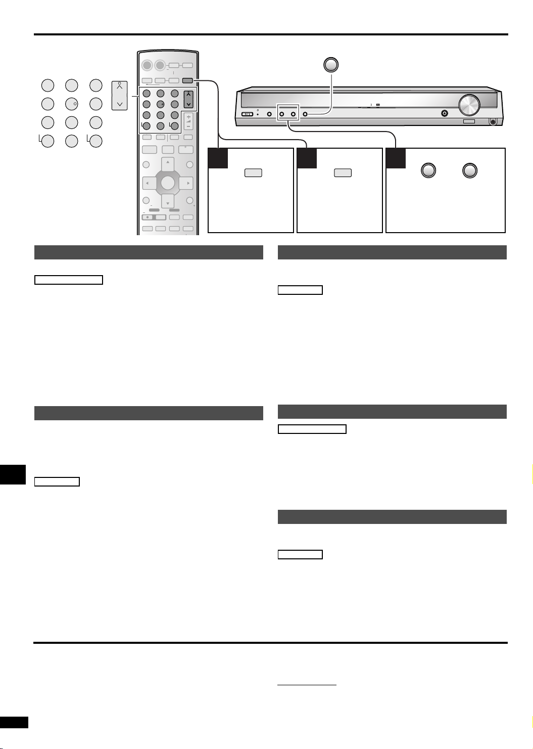
The radio
AV SYSTEMRECEIVER
DVD
PLAYER
ANALOG 6CH
DVD
VCR
23
-/--
>
10
=
SLOW/SEARCH
i
t
ENTER
TV
TV/AV
-
H.BASS/
-
C.FOCUS
TV
-
TUNER/
-
BAND
CH
VOLUME
y
PLAY
q
FUNCTIONS
RETURN
Select “TUNER”.
MUTING
-
LEVEL/
-
TEST
-
TUNER/
-
BAND
23
1
45 6
7089
DIRECT TUNING
DISC
-/--
>
=
10
CH
^^
DRIVE
SELECT
RECORDER
1
45 6
7089
DIRECT TUNING
DISC
SKIP
u
STOP PAUSE
gh
DIRECT NAVIGATOR
TOP MENU
SUB MENU/
PLAY LIST
TV VOL TV VOL
DVD REC
REC MODE
REC
INPUT MODE
SUBWOOFER
TONE/
Direct tuning
Input the frequency of the station.
Remote control
1.Press [-TUNER/–BAND] to select “TUNER”.
2.Press and hold [-TUNER/–BAND] to select “FM” or
“AM”.
3.Press [DISC, DIRECT TUNING].
4.Press the numbered buttons to enter the frequency.
e.g. To select 107.90 MHz, press [1] → [0] → [7] → [9]→ [0]
• If you do not press a button while the cursor is flashing, the
display returns to the frequency being received.
• If the frequency has not been input correctly, “ERROR” will be
displayed.
MENU
%DIGITAL
INPUT SELECTOR
2
2
MENU
TUNE
-
2 31
TUNER/
-
%PL
2
BAND
Press and hold
Select “FM” or
“AM”.
Select the frequency.
Auto tuning starts if you press
and hold the button.
Manual presetting
Preset the stations one at a time.
Preparation: Tune to the station you want to preset.
Main unit
1.Press [MENU] to select “MEMORY”.
2.Press [TUNE 2 or 1] to select the channel.
3.Press [MENU] to store.
To c a n ce l
Press and hold [MENU].
For your reference
FM stations can also be preset in the MONO mode.
H. BASS
TUNE
VOLUME
DOWN
UP
PHONES
2
Automatic presetting
The FM stations the unit can receive are preset in channels 1 to
30. The AM stations the unit can receive are preset in channels
21 to 30. (FM stations are replaced if any were preset in these
channels.)
Preparation: Select “FM” or “AM”.
Main unit
1.Press [MENU] to select “MEMORY”.
2.Press and hold [TUNE 2].
The tuner presets all the stations it can receive into the channels
in ascending order.
Operations
If you press and hold [TUNE 1], it starts from the current
frequency.
During automatic presetting, the memory indicator (M) flashes
and the frequency scrolls. The memory indicator and channel
numbers are displayed for a second when a station is preset.
The last station to be preset is displayed when presetting
finishes.
To cancel
Press and hold [MENU].
To switch between FM and AM on the main unit
1. Press [MENU] to select “BAND”.
2. Press [TUNE 2 or 1] to select “FM” or “AM”.
3. Press [MENU].
RQT7953
18
Selecting channels
Remote control
Press [
1, CH, 2].
or
Press the numbered buttons.
For channels 1 to 9, press the corresponding number.
For channels 10 or over, press [
e.g. To select channel 21: [
≧ 10, -/--], then the two digits.
≧ 10, -/--] → [2] → [1]
FM mode
You can improve FM reception by switching reception to
monaural.
Main unit
1.Press [MENU] to select “FM MODE”.
2.Press [TUNE 2 or 1] to select “MONO”.
Select “AUTO” to cancel.
3.Press [MENU].
“MONO” lights.
To change the AM frequency step
If the correct AM frequency cannot be tuned in, change the
frequency step to suit your area.
On the main unit
1. Press [MENU] to select “AM ALLOC”.
2. Press [TUNE 2 or 1] to select “9” or “10”.
3. Press [MENU].
(The frequency step changes from 9 kHz to 10 kHz.).
Page 19
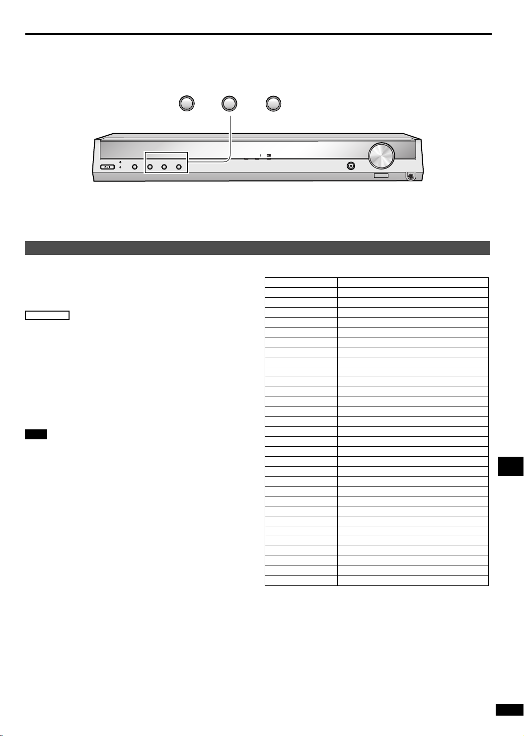
The radio
2
%DIGITAL
INPUT SELECTOR
2
TUNE
2
2
TUNE
MENU
RDS broadcasts
(For continental Europe and the United Kingdom)
This unit can display the text data transmitted by the radio data
system (RDS) available in some areas.
“RDS” lights while RDS signals are being received.
RDS displays may not be available if reception is poor.
Main unit
1.Press [MENU] to select “DISPLAY”.
2.Press [TUNE 2 or 1] to select “FREQ”, “RDS PS”,
or “RDS PTY”.
3.Press [MENU].
FREQ: Frequency display
RDS PS: Pogram service, the station name (default setting)
RDS PTY: Program type
Note
This unit does not have the emergency broadcast system (EBS)
that tunes automatically into emergency broadcasts.
MENU
VOLUME
%PL
H. BASS
DOWN
PTY Displays
NEWS News
AFFAIRS Current affairs
INFO Information
SPORT Sport
EDUCATE Education
DRAMA Drama
CULTURE Culture
SCIENCE Science
VAR IE D Var ied
POP M Pop music
ROCK M Rock music
M. O. R. M Middle-of-the-road Music
LIGHT M Light classical
CLASSICS Serious classical
OTHER M Other music
WEATHER Weather information
FINANCE Finance
CHILDREN Children
SOCIAL A Social affairs
RELIGION Religion
PHONE IN Phone in
TRAVEL Travel
LEISURE Leisure
JAZZ Jazz music
COUNTRY Country music
NATIONAL National music
OLDIES Oldies
FOLK M Folk music
DOCUMENT Documentary
TEST Test broadcast
ALARM Emergency announcement
UP
PHONES
Operations
19
RQT7953
Page 20
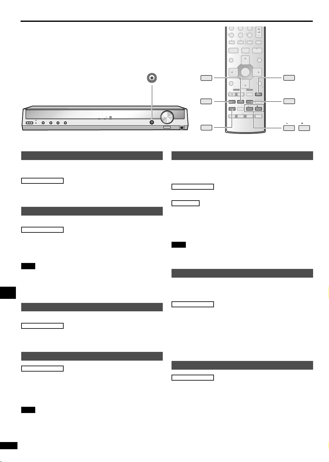
Other functions
H. BASS
%DIGITAL
2
2
MENU
TUNE
INPUT SELECTOR
Input mode
This unit automatically detects whether input is digital or
analogue, but you can fix the input mode.
Remote control
Press [INPUT MODE] to select "AUTO", "ANALOG" or
"DIGITAL".
Tone
You can adjust the level of the bass and treble.
Remote control
1.Press [TONE/BALANCE] to select “BASS” or
“TREBLE”.
2.Press [–/L] or [+/R] to adjust bass/treble.
Note
• Input signals must be either analogue or PCM, and Dolby Pro
LogicII and SFC must be off.
• (SC-HT17) You cannot adjust the tone if DVD ANALOG 6CH
is selected.
Balance
You can adjust the balance of the front speakers.
Remote control
Operations
1.Press [TONE/BALANCE] to select “BALANCE”.
2.Press [–/L] or [+/R] to adjust.
Subwoofer level
Remote control
Press [SUBWOOFER].
Adjust the level in 5 steps:
SW MIN, SW 5, SW 10, SW 15, and SW MAX.
Select SW - - - to stop output.
Note
• Sound can be distorted if you raise the volume while
subwoofer level is high. Reduce subwoofer level if this occurs.
• (SC-HT17) You cannot adjust the subwoofer level if DVD
ANALOG 6CH is selected.
RQT7953
20
%PL
H. BASS
7089
-/--
VOLUME
DOWN
DIRECT TUNING
DIRECT NAVIGATOR
TOP MENU
SUBWOOFER
INPUT MODE
UP
PHONES
TONE/
BALANCE
SUB MENU/
PLAY LIST
TV VOL TV VOL
INPUT MODE
BALANCE
>
DISC
u
STOP PAUSE
REC
TONE/
OFF
10
=
SLOW/SEARCH
SKIP
i
t
gh
ENTER
DVD REC
TV
REC MODE
TV/AV
-
H.BASS/
SUBWOOFER
-
C.FOCUS
EFFECT
/L /R
%PL
MUSIC
SFC
PLAY
MUTING
AV/MOVIE
y
q
FUNCTIONS
RETURN
-
LEVEL/
-
TEST
H.Bass
You can enhance low-frequency sound so that heavy bass
sound can be heard clearly, even if the acoustics of your room
are not optimal.
Remote control
Press [-H.BASS/–C.FOCUS].
Main unit
Press [H.BASS].
The indicator lights.
To cancel
Press [-H.BASS/–C.FOCUS] or [H.BASS] again.
Note
• You cannot use H.Bass when you are using headphones.
• Actual effect depends on the disc.
Center focus
(Disc where the dialogue is recorded in the center channel)
You can make the sound of the center speaker seem like it is
coming from within the television.
Remote control
Press and hold [-H.BASS/–C.FOCUS].
“C.FOCUS” lights.
The factory setting is off.
The center focus cannot be used in the following cases:
• When input signal is PCM or analogue stereo.
• (SC-HT17) When DVD ANALOG 6CH is selected.
Muting
Remote control
Press [MUTING].
To cancel
Press [MUTING] again.
Muting is also cancelled when the unit is turned off.
MUTING
-
H.BASS/
-
C.FOCUS
/L /R
Page 21
Other functions
INPUT SELECTOR
2
2
TUNE
INPUT SELECTOR
TUNE
2
MENU
TOP MENU
2
MENU
%DIGITAL
%PL
H. BASS
VOLUME
DOWN
UP
INPUT MODE
PHONES
ENTER
SUB MENU/
PLAY LIST
TV VOL TV VOL
DVD REC
REC MODE
REC
INPUT MODE
SUBWOOFER
TONE/
BALANCE
OFF
EFFECT
%PL
-
-
MUSIC
TV/AV
H.BASS/
C.FOCUS
TV
/L /R
SFC
RETURN
MUTING
-
LEVEL/
-
TEST
AV/MOVIE
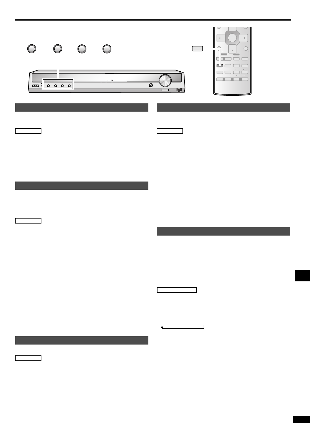
A/D attenuator
Turn the A/D attenuator on if “OVERFLOW” lights frequently
when using 2-channel analogue input.
Main unit
1.Press [TUNE 2 and 1] at the same time to enter the
setup mode.
2.Press [INPUT SELECTOR] to select “A/D ATT”.
3.Press [TUNE 2 or 1] to select “ON” or “OFF”.
4.Press [TUNE 2 and
1] at the same time to exit the
setup mode.
Dynamic range compression
Change this setting to listen to software recorded with Dolby
Digital at low volume (such as late at night) and maintain audio
clarity. It reduces the peak level in loud scenes without affecting
the sound field.
Main unit
1.Press [TUNE 2 and 1] at the same time to enter the
setup mode.
2.Press [INPUT SELECTOR] to select “DR COMP”.
3.Press [TUNE 2 or 1] to select “OFF”, “STANDARD”
or “MAX”.
4.Press [TUNE 2 and 1] at the same time to exit the
setup mode.
OFF:
The software is played with the original dynamic range (factory
setting).
STANDARD:
The level recommended by the producer of the software for
household viewing.
MAX:
The maximum allowable compression (recommended for night
viewing).
Dimmer
Dim the display for better viewing in a darkened room.
Main unit
1.Press [MENU] to select “DIMMER”.
2.Press [TUNE 2 or 1] to select “OFF” or “ON”.
3.Press [MENU].
Sleep timer
The SLEEP timer can turn the unit off after a set time.
It does not control any other components.
Main unit
1.Press [MENU] to select “SLEEP”.
2.Press [TUNE 2 or 1] to select the desired time.
The display changes as follows:
OFF
v SLEEP 30 v SLEEP 60 v SLEEP 90 v
SLEEP 120 (minutes)
3.Press [MENU].
The display dims even when the dimmer is “OFF”.
To check the setting
1. Press [MENU] to select “SLEEP”.
2. Press [TUNE 2 or 1] once. The time remaining appears.
3. Press [MENU].
To change a setting
Repeat the procedure from the beginning.
PCM/DTS fix mode
In rare cases, the unit may have trouble recognizing the digital
signals on discs.
• With the PCM signals on CDs, this may cause the beginning
of a track to be cut off. Engage the PCM FIX mode if this
occurs.
• With DTS, the signals may not be recognized at all. Engage
the DTS FIX mode if this occurs.
While the input source is selected:
Remote control
1.Press [INPUT MODE] to select “DIGITAL”
2.Press and hold [INPUT MODE] for four seconds.
The current mode is displayed. Press again to change the mode.
Each time you press the button:
AUTO → PCM FIX → DTS FIX
When a FIX mode is on, the unit cannot process other signals.
This may cause noise to be output. Select “AUTO” if this occurs.
The mode returns to AUTO when you switch the unit to standby.
For your reference
If you are playing a DTS CD that contains both DTS and PCM,
but it isn’t playing properly, then do the following after step 1
above:
On the Main unit
1. Press [MENU] to select “DTS-PCM”.
2. Press [TUNE 2 or 1] to select “ON”.
3. Press [MENU].
If this causes noise to occur, return the setting to “OFF”. (This
setting is effective for each digital source.)
Operations
RQT7953
21
Page 22
Other functions
S
S
TOP MENU
SUB MENU/
PLAY LIST
TV VOL TV VOL
DVD REC
REC
EFFECT
INPUT MODE
TONE/
BALANCE
OFF
ENTER
REC MODE
SUBWOOFER
EFFECT
%PL
TV/AV
-
H.BASS/
-
C.FOCUS
MUSIC
TV
/L /R
SFC
RETURN
MUTING
-
LEVEL/
-
TEST
AV/MOVIE
-
LEVEL/
-
TEST
/L /R
Making a recording
INPUT SELECTOR
%DIGITAL
INPUT SELECTOR
2
2
MENU
TUNE
%PL
H. BAS
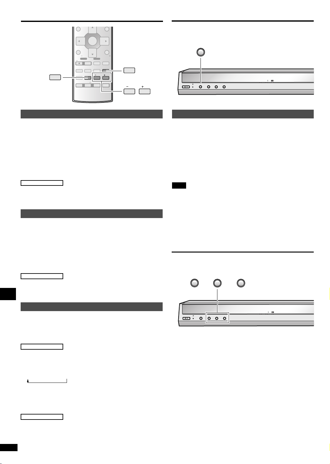
Center Width Control "C-WDTH"
You can adjust the effect of MUSIC and PANORAMA with the
center width control.
This adjustment helps you realise a more natural sound image
when listening to music. Move sound out into the front speakers
to improve the overall front image, or add sound to the center
speaker to fix the center image.
You can choose a level between 0 (the center speaker is
dominant) and 7 (center sound is spread out).
The default level is 3.
Remote control
1.Press [EFFECT] to select “C-WDTH”.
2.Press [–/L] or [+/R] to adjust the effect.
Dimension Control "DIMEN"
You can adjust the effect of MUSIC and PANORAMA with the
dimension control.
You can make up for differences in the output level of the front
and surround speakers.
You can choose a level between –3 and +3 — Increase the level
to move sound to the front speakers, decrease to move it to the
surround speakers.
The default is level 0.
Remote control
1.Press [EFFECT] to select “DIMEN”.
2.Press [–/L] or [+/R] to adjust the effect.
Recording on other equipment
You can record to a unit connected to DVR/VCR OUT.
You can record any analogue source except DVR/VCR IN.
1.Press [INPUT SELECTOR] to select the source to be
recorded.
2.Begin recording.
Follow your recording unit’s operating instructions.
3.Start the source to be recorded.
Note
• (SC-HT17) When you select DVD ANALOG 6CH mode, only
sound from the front left and right channels is recorded.
• This unit cannot record digital sources. Connect through the
analogue terminals and select "ANALOG" input.
The RESET function
2
TUNE
2
MENU
Adjusting SFC effects
You can adjust the sound field by adjusting the level of the
speakers and the delay time of the surround speakers. These
adjustments can be made for each SFC mode.
Operations
To adjust the speaker level
Remote control
1.Press [-LEVEL/–TEST] to select the speaker
channel.
Each time you press the button:
C →RS→ LS→ SW
2.Press [–/L] or [+/R] to adjust the level.
C, RS, and LS:–10 dB to +10 dB
SW:– – – (off) ↔ MIN ↔ 1 – 19 ↔ MAX
To adjust the delay time
Remote control
1. Press [EFFECT].
2. Press [–/L] or [+/R] to change the delay time.
The default is 50 mSEC. (10 mSEC – 100 mSEC)
RQT7953
22
%DIGITAL
INPUT SELECTOR
2
2
MENU
TUNE
%PL
The operation settings for the unit will be initialised to the
settings made at the time of shipment.
However, any preset radio stations will not be erased.
1.Press [MENU] to select “RESET”.
2.Press [TUNE 2 or 1] to select “YES”.
To cancel, select “NO”.
3.Press [MENU].
H. BAS
Page 23
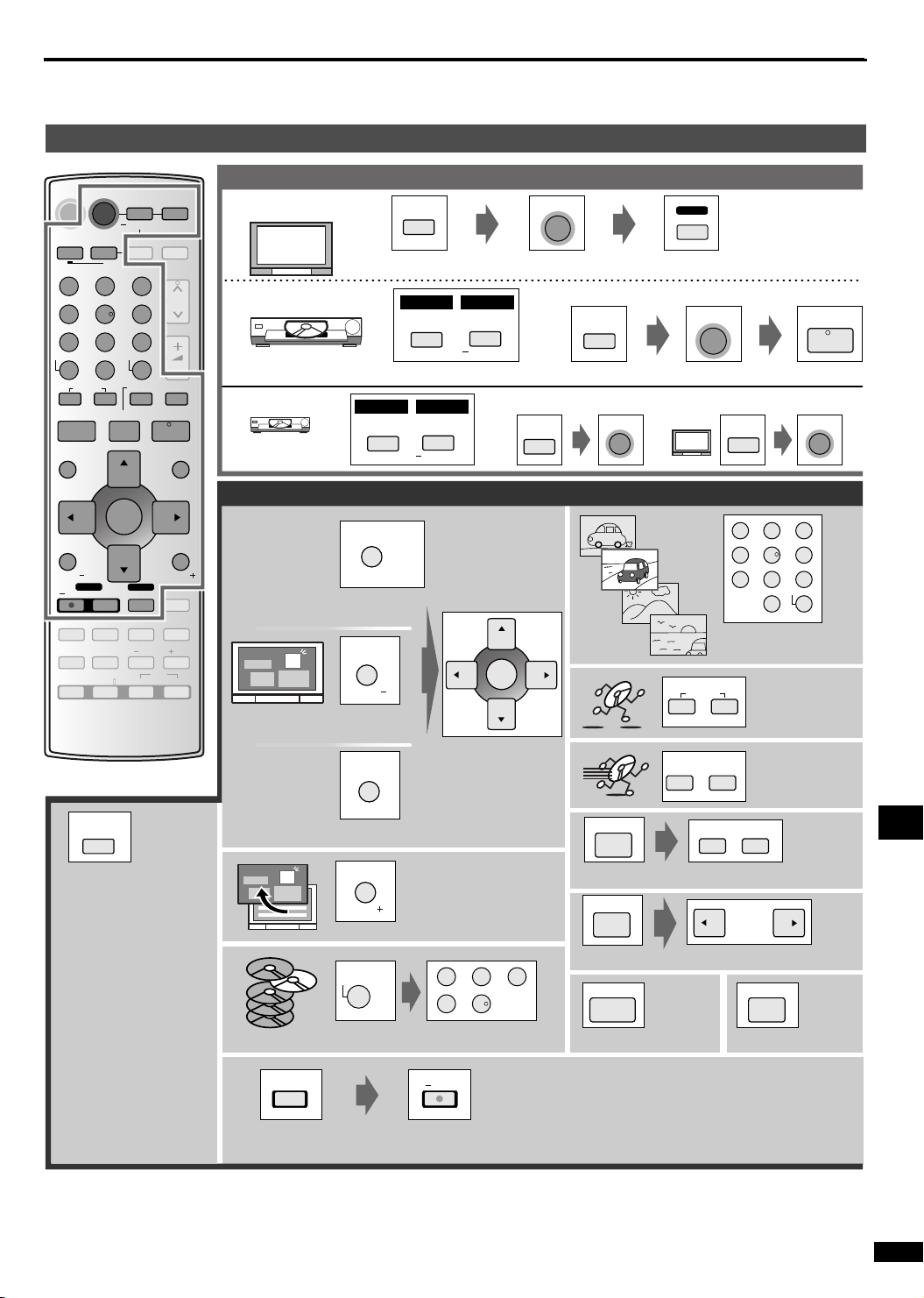
Remote control operation guide
This remote control can operate Panasonic and Technics audiovisual components that have remote control sensors.
You may need to change the remote control code. (è page 25)
Note that this remote control cannot operate some equipment and that it may not be able to perform some operations.
DVD
AV SYSTEMRECEIVER
DVD
TV
DVD
RECORDER
23
SKIP
i
ENTER
DVD REC
REC MODE
SUBWOOFER
EFFECT
%PL
PLAYER
ANALOG 6CH
-
TUNER/
VCR
-
VOLUME
-/--
>
10
=
SLOW/SEARCH
t
PLAY
FUNCTIONS
TV
MUTING
TV/AV
-
H.BASS/
-
-
C.FOCUS
-
/L /R
SFC
MUSIC
AV/MOVIE
BAND
CH
y
q
RETURN
LEVEL/
TEST
^^
DRIVE
SELECT
1
45 6
7089
DIRECT TUNING
DISC
u
STOP PAUSE
gh
DIRECT NAVIGATOR
TOP MENU
SUB MENU/
PLAY LIST
TV VOL TV VOL
REC
INPUT MODE
TONE/
BALANCE
OFF
Watching DVDs
Switch on
Switch off
SC-HT15 SC-HT17
TV
Switch on the television and select input
SC-HT15 SC-HT17
DVD
PLAYER
DVD
PLAYER
ANALOG 6CH
Switch on the player and start play
DVD
PLAYER
DVD
PLAYER
ANALOG 6CH
or
DVD
RECORDER
Operating the DVD player/DVD recorder
DIRECT NAVIGATOR
TOP MENU
Show disc menus
MENU
SUB MENU/
PLAY LIST
TV VOL
Show disc menus
ENTER
AV SYSTEM
^
or
DVD
RECORDER
AV SYSTEM
^
^
TV/AV
u
TV
SKIP
AV SYSTEM
^
^
i
TV
1
AV SYSTEM
^
^
23
45 6
7089
-/--
>
10
=
Start play from a
selected item
Skip items
during play
PLAY
q
Select and enter
DRIVE
SELECT
Switch between DVD
and HDD
[DVD recorder with HDD]
MENU
Show player menus
MENU
FUNCTIONS
Clear menus or return to
RETURN
previous menus
TV VOL
menu items
SLOW/SEARCH
t
PAUSE
h
Start slow-motion play
PAUSE
h
Search through
y
the disc
SLOW/SEARCH
t
y
When you cannot switch
to the disc or hard disk
drive, after performing
the following operations,
press the button again.
1. While pressing
[ENTER], press and
23
DIRECT TUNING
DISC
1
45
Specify a disc [5-disc changer]
To view frame-by-frame
STOP
g
Stop play
PAUSE
h
Pause play
hold [8] or [9] for
approximately 2
seconds.
REC MODE
REC
2. Press [DVD
RECORDER].
The factory setting is [9].
Select a recording
mode
Start recording
(Press and hold)
When using a Panasonic DVD recorder
Change the unit’s remote control code to match the remote control code of the DVD recorder.
Preparations: Check the remote control code of the DVD recorder.
For about one second hold down both [ENTER] and the button ([1], [2] or [3]) which the same number as the remote control
code set by the DVD recorder.
The factory setting is [1].
Operations
RQT7953
23
Page 24
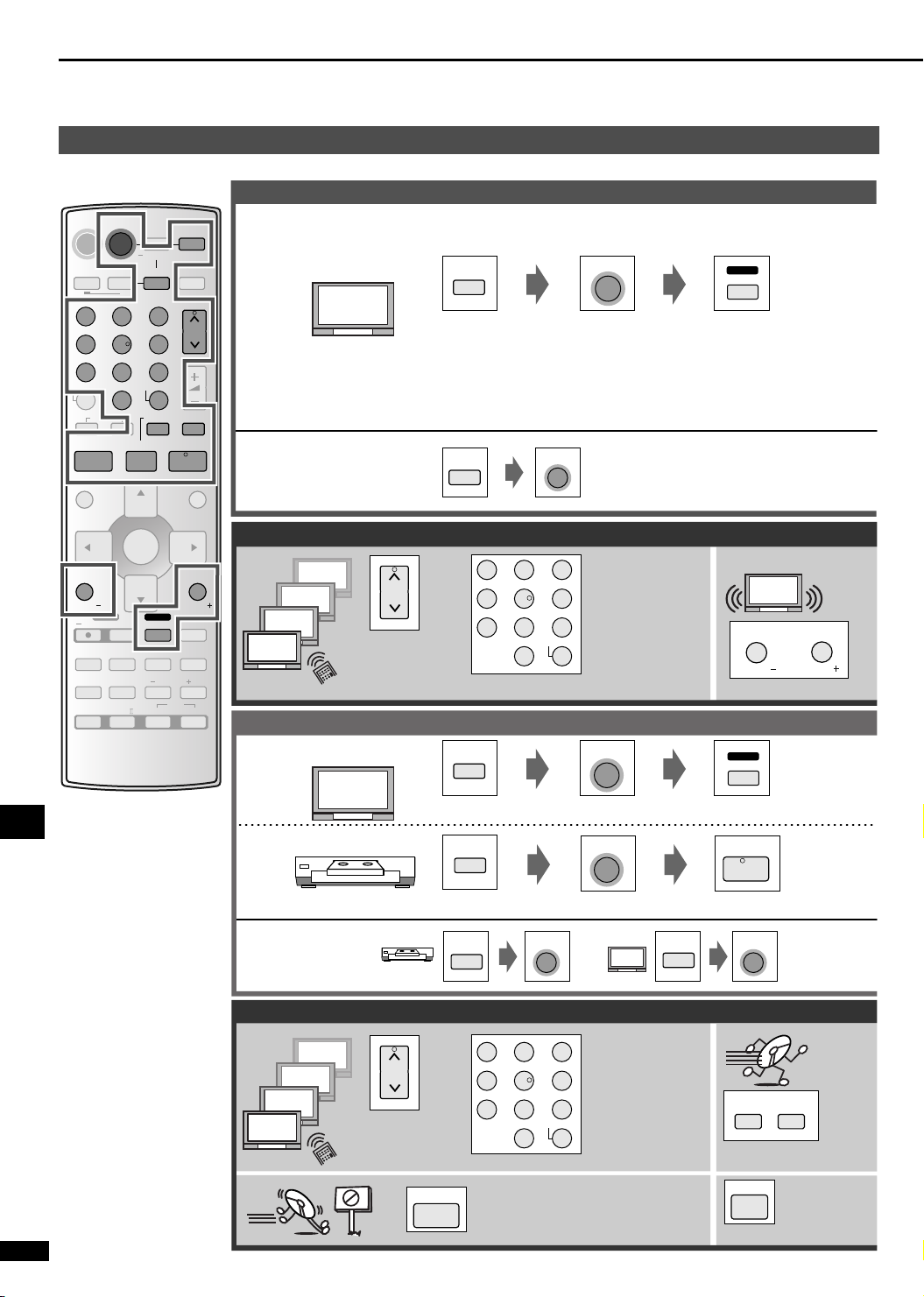
Remote control operation guide
TV/VCR
Watching TV
AV SYSTEMRECEIVER
DVD
TV
DVD
RECORDER
23
SKIP
i
ENTER
DVD REC
REC MODE
SUBWOOFER
EFFECT
%PL
PLAYER
ANALOG 6CH
-
TUNER/
VCR
-
BAND
VOLUME
-/--
>
10
=
SLOW/SEARCH
t
PLAY
q
FUNCTIONS
RETURN
TV
MUTING
TV/AV
-
H.BASS/
-
LEVEL/
-
C.FOCUS
-
/L /R
SFC
MUSIC
AV/MOVIE
CH
y
TEST
^^
DRIVE
SELECT
1
45 6
7089
DIRECT TUNING
DISC
u
STOP PAUSE
gh
DIRECT NAVIGATOR
TOP MENU
SUB MENU/
PLAY LIST
TV VOL TV VOL
REC
INPUT MODE
TONE/
BALANCE
OFF
Switch on
Switch off
Operating the TV
4
3
2
1
Watching videotapes
Switch on
Change channels
sequentially
TV
Switch on the television and select input
TV
AV SYSTEM
^
23
1
CH
45 6
7089
TV
-/--
>
10
=
Switch on the television and select input
AV SYSTEM
^
Select channels
directly
AV SYSTEM
^
TV
TV/AV
SUB MENU/
PLAY LIST
TV VOL
RETURN
TV VOL
Adjust the volume
TV
TV/AV
24
Operations
VCR
AV SYSTEM
^
PLAY
q
Switch on the player and start play
Switch off
VCR
AV SYSTEM
^
TV
AV SYSTEM
^
Operating the video deck
23
4
3
CH
2
1
RQT7953
Change channels
sequentially
STOP
1
45 6
7089
Stop play
g
Select channels
directly
-/--
>
10
=
SLOW/SEARCH
t
y
Rewind or fast-forward
PAUSE
h
Pause play
Page 25
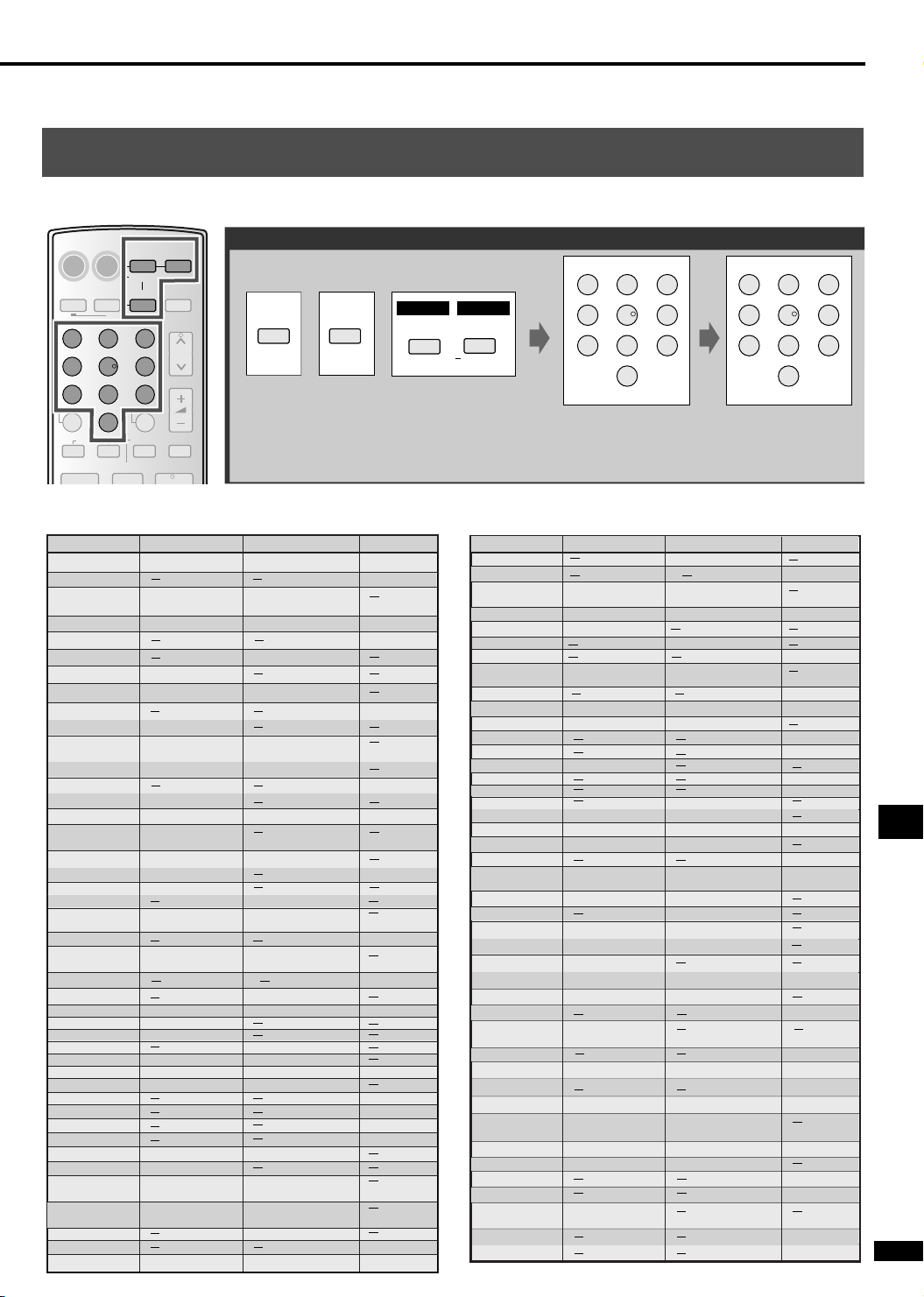
Using this remote control to operate equipment manufactured by Panasonic, Technics, and
other companies
It can also operate some other brands of televisions, video cassette players, and DVD players. Check the table for the brand and enter
the code as follows.
AV SYSTEMRECEIVER
DVD
TV
DVD
RECORDER
23
SKIP
i
ENTER
ENTER
DVD REC
REC MODE
SUBWOOFER
EFFECT
%PL
PLAYER
ANALOG 6CH
-
TUNER/
VCR
-
BAND
CH
VOLUME
-/--
>
10
=
SLOW/SEARCH
t
y
PLAY
q
FUNCTIONS
TV VCR DVD player
07,11,28,36
RETURN
37
05,11,12
TV
TV/AV
MUTING
-
H.BASS/
-
LEVEL/
-
C.FOCUS
32
-
TEST
28,36 01,26,29,30,33
/L /R
SFC
MUSIC
AV/MOVIE
12,32,38
^^
DRIVE
SELECT
1
45 6
7089
DIRECT TUNING
DISC
u
STOP PAUSE
gh
DIRECT NAVIGATOR
Code table
TOP MENU
TOP MENU
PANASONIC 01,29,30,31
AIWA
SUB MENU/
AKAI
PLAY LIST
ALBA 02,06,23
TV VOL TV VOL
APEX
REC
B AIRD
BAUR
INPUT MODE
BLAUPUNKT
TONE/
BALANCE
BOSE
BRANDT 26,41
OFF
BUSH 02,05,10,11
Changing the codes
TV VCR DVD player
TV
Press and hold the button corresponding to
the equipment
The remote control outputs the on/off signal.
If the code is correct, the equipment turns on or off.
If it doesn’t, try entering another code.
• Re-enter the codes after you change the batteries.
01,29,30
06,08,16,17
19,37
08,10,37
02,09,23
VCR
01
23
20,35,36
39
DAEWOO 11,12,32 15
DENON 01,17
DUAL 32
FERGUSON 11,12 31 02
FINLUX 11,12,22,23
24,25,40
FISHER 37 05,07,10,11,12
FUNAI 02,38
GOLDSTAR 11,12
GOLDSTAR/LG
GOODMANS
GO-VIDEO 12
GRUNDIG
11,12,25,32 02,03,18,23
28,36
03,04,36,37
27,33
02,23,26,28
32,33
HARMAN KARDON
HCM
HITACHI
ICE
INNO HIT
ITT 08,10,11,37
ITT/NOKIA
JVC 18 20,21
KENDO 40 08,09,37
KENWOOD
KLH
KONIKA
KOSS
LOEWE 14,33 03,32
LOEWE OPTA 32
LUXOR
MATSUI
METZ
MINTEK
MITSUBISHI
01,09,26,41
21,39
34
05,07,37 18,27,37
37
02,05,06,07,10
11,12,25,37,38
14,19,28,36 17,19,21,32
02,23
13,14
08,10,11,17
19,37
03,05,09
01
18
34
11
09
15,29
32
19
31
38
06
SC-HT15 SC-HT17
DVD
PLAYER
DVD
PLAYER
ANALOG 6CH
NEC
NEXTBASE
NOKIA
NORDMENDE 20,21
OCEANIC
OKANO 06
ONKYO
ORION
ORITRON
PHILIPS 11,12,13,15 22,32,33,34,35
PHONOLA
PIONEER
POLKAUDIO
RADIOLA 11,12
RAITE
RCA
RFT
ROADSTAR 39 02,03,18,23,27
SABA 26,41 21 02
SALORA 07,37 08,11,17,19,37
SAMPO
SAMSUNG 11,12,15,21
SANYO 07,17,25,37 07,10,11
SCHAUB LORENZ
SCHNEIDER 11,12 02,03,18,23,27,32
SEG 39,40 02,18,23,27
SELECO 11,24
SHARP 17,20 22 08
SIEMENS 11,12,17,28,36 03,10,11,32
SILVANIA
SINUDYNE 02,05,11,12
SMC
SONY 16 24,25,26 05,26,27,28
TECHNICS
THOMSON 05,26,41 21 02
THORN 06,08,11,12
TOSHIBA 03,04,06,08 15,17,19,32 04
UNIVERSUM
VENTURER
VIALTA
WHITE WESTIN
HOUSE
YAMAHA
ZENITH 07,12
23
1
45 6
7089
Enter the first digit
TV
05,07,37
26,41
27,35
02,03,05,10
11,12,38
11,12
25,34,39
22,24,38,40
14,16,25,32
39
11,12,22,40
1
45 6
7089
Enter the second digit
VCR
04,21,36,37
08,10,11,18
22,27,37
05,09
32
33
15,16,18,27 10
10
10
03,08,32,37
23
DVD player
37
02
21,33
24
04,16
03
16
13
02
14
18
25
01
32
31
01,22,30
Operations
RQT7953
25
Page 26
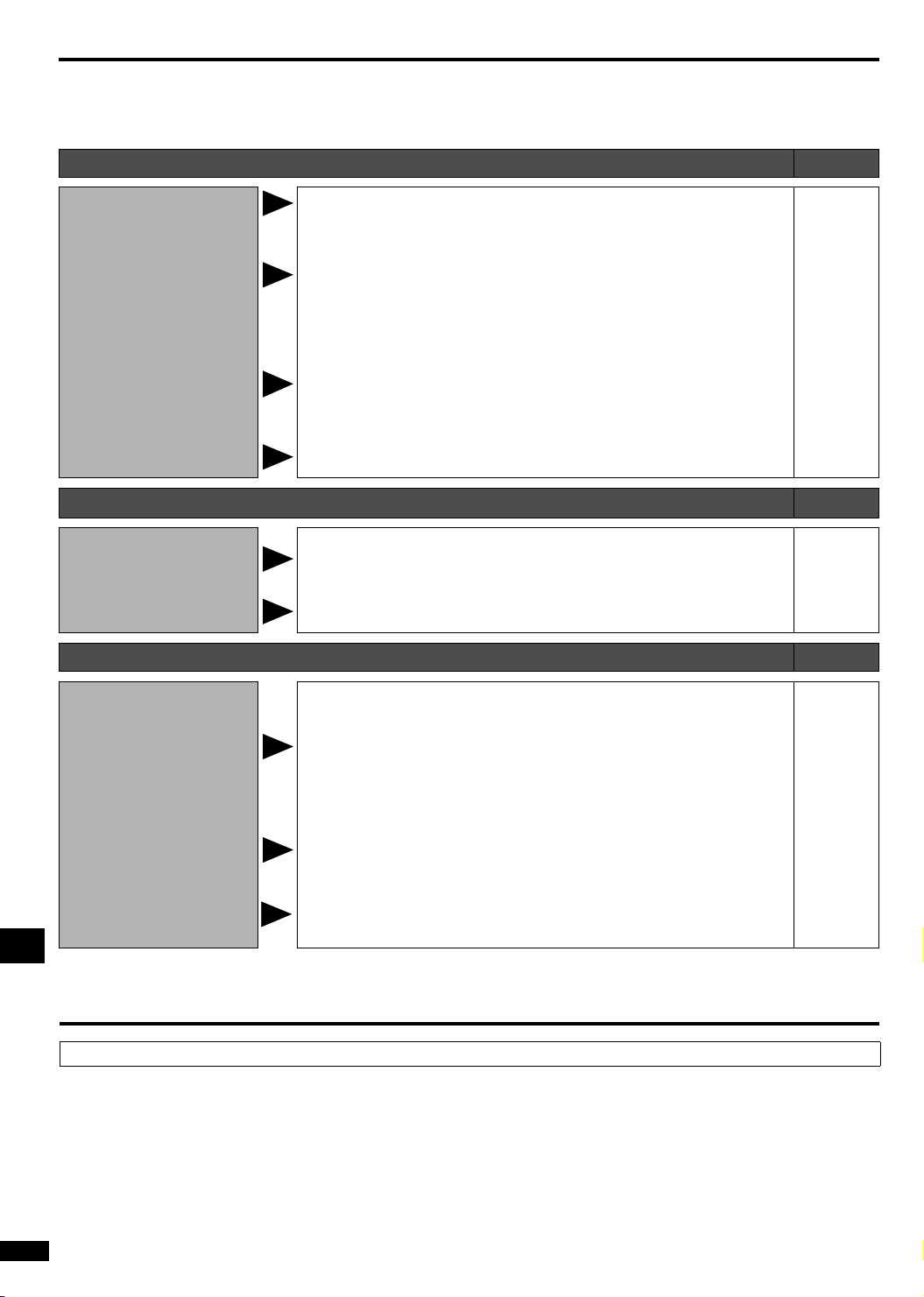
Troubleshooting guide
Before requesting service, make the below checks.
If you can’t fix the unit as described or if something not listed here occurs, contact your dealer.
Common problems Pages
No power.
No sound.
“F76” appears on the
display, and the unit turns
off.
“FAN LOCK” appears on
the display.
“F 70” appears on the
display.
Sound is not heard from
the center, surround, or
subwoofer speakers.
Cannot use Dolby Pro
LogicII or SFC.
The radio cannot be tuned
in or there is a lot of noise
and interference.
• Ensure the AC mains lead and system cable are connected. 9
• Turn the volume up.
• Check connections to speakers and other equipment.
• Select the correct source.
• Change the D-INPUT setting to suit the type of connection you have made.
• Check that the digital signals can be decoded by this unit.
• Turn PCM FIX or DTS FIX off.
• Determine and correct the cause, then turn the unit on.
Causes include:
− Shorting (bare wires touching) of positive and negative speaker wires.
− Using the subwoofer in a hot environment without proper ventilation.
Consult your dealer if the problem occurs again after turning the unit on.
• Turn the unit off, disconnect the AC mains lead, and consult your dealer. –
15
7-12
15
13
9
21
7
–
Sound Pages
• The source may be stereo. Use Dolby Pro LogicII or SFC. 15
• You cannot use Dolby Pro LogicII or SFC when input is PCM with
sampling frequencies of 96 or 88.2 kHz.
15
Radio Pages
• Connect the appropriate antenna. (You may need an outdoor antenna or
one with more elements.)
• Adjust the position of the FM or AM antenna.
• Reduce the treble.
• Turn off nearby televisions, video decks and DVD players.
• Separate the antenna from other cables, leads, and appliances.
12
12
20
–
–
• Press and hold [H.BASS] on the main unit so “DEFEAT” appears (the DSP
There is a lot of noise
when listening to AM.
The correct AM frequency
cannot be tuned in. • Change the frequency step.
is defeated). This should reduce noise. The unit cannot play multiple
channel sound while the DSP is defeated, so repeat this to reengage the
DSP.
18
Maintenance
Reference
If the surfaces are dirty
To clean this unit, wipe with a soft, dry cloth.
• Never use alcohol, paint thinner or benzine to clean this unit.
• Before using chemically treated cloth, carefully read the instructions that came with the cloth.
RQT7953
26
20
Page 27

Specifications (DIN 45 500)
n AMPLIFIER SECTION
RMS output power of each channel driven
(at 240 V for areas other than continental Europe)
10 % total harmonic distortion
1 kHz front CH [SC-HT17] 170 W per channel (6 Ω)
1 kHz surround CH [SC-HT17] 70 W per channel (4 Ω)
1 kHz center CH [SC-HT17] 260 W per channel (4 Ω)
100 Hz subwoofer CH [SC-HT17] 260 W per channel (4 Ω)
Total RMS output power [SC-HT17] 1000 W
DIN power output: Dolby Digital Mode
(at 240 V for areas other than continental Europe)
T.H.D. 1% (Each channel driven)
1 kHz front CH [SC-HT17] 100 W per channel (6 Ω)
1 kHz surround CH [SC-HT17] 45 W per channel (4 Ω)
1 kHz center CH 150 W per channel (4 Ω)
100 Hz subwoofer CH 160 W per channel (4 Ω)
Total DIN output power [SC-HT17] 600 W
DIN power output: Stereo Mode
(at 240 V for areas other than continental Europe)
T.H . D. 1 %
1 kHz front CH [SC-HT17] 90 W per channel (6 Ω)
100 Hz subwoofer CH 160 W per channel (4 Ω)
Total DIN output power [SC-HT17] 340 W
Total harmonic distortion
Half power at 1 kHz (Front CH) [SC-HT17] 0.1 % (6 Ω)
Input sensitivity
DVD, DVR/VCR, TV, GAME/AUX 400 mV, IHF’66
[SC-HT17] S/N at rated power (6 Ω)
DVD, DVR/VCR, TV, GAME/AUX 75 dB (85 dB, IHF’66)
[SC-HT15] S/N at rated power (4 Ω)
DVD, DVR/VCR, TV, GAME/AUX 75 dB (85 dB, IHF’66)
Input impedance
DVD, DVR/VCR, TV, GAME/AUX
Tone controls
BASS 50 Hz, +10 to -10 dB
TREBLE 20 kHz, +10 to -10 dB
Digital input OPTICAL 2
COAXIAL 1
n VIDEO SECTION (SC-HT17)
Output voltage at 1 V input (unbalanced) 1±0.1 Vp-p
Maximum input voltage 1.5 Vp-p
Input/output impedance 75 Ω
n FM TUNER SECTION
Frequency range 87.50-108.00 MHz
Sensitivity
S/N 30 dB 1.5 µV/75 Ω
S/N 26 dB 1.3 µV/75 Ω
S/N 20 dB 1.2 µV/75 Ω
IHF usable sensitivity (IHF’58) 1.5 µV/75 Ω
IHF 46 dB stereo quieting sensitivity 22 µV/75 Ω
Total harmonic distortion
MONO 0.2 %
STEREO 0.3 %
S/N
MONO 60 dB (71 dB, IHF)
STEREO 58 dB (65 dB, IHF)
Frequency response 20 Hz-15 kHz, +1 dB, -2 dB
Image rejection at 98 MHz 40 dB
IF rejection at 98 MHZ 70 dB
Stereo separation (1 kHz) 40 dB
Antenna terminal 75 Ω (unbalanced)
n AM TUNER SECTION
Frequency range 522-1611 kHz (9 kHz steps)
Sensitivity 450 µV/m
Selectivity (at 999 kHz) 35 dB
n SPEAKER SECTION
Front speaker (SC-HT17:SB-FS930) (SC-HT15:SB-FS880)
Typ e [SC-HT17] 2 Way, 3 Speakers, Bass-ref.
[SC-HT15] 2 Way, 2 Speaker, Bass-ref.
Speaker unit
Full range [SC-HT17] 8 cm cone type x 2, 6 Ω
Super tweeter [SC-HT17] 6 cm Ring Shaped Dome type, 6 Ω
[SC-HT15] 6 cm Ring Shaped Dome type, 4 Ω
[SC-HT15] 60 W per channel (4 Ω)
[SC-HT15] 60 W per channel (4 Ω)
[SC-HT15] 220 W per channel (4 Ω)
[SC-HT15] 240 W per channel (4 Ω)
[SC-HT15] 700 W
[SC-HT15] 35 W per channel (4 Ω)
[SC-HT15] 35 W per channel (4 Ω)
[SC-HT15] 450 W
[SC-HT15] 35 W per channel (4 Ω)
[SC-HT15] 230 W
[SC-HT15] 0.1 % (4 Ω)
47 kΩ
530-1620 kHz (10 kHz steps)
[SC-HT15] 8 cm cone type, 4 Ω
Input power (IEC) [SC-HT17] 170 W (Max)
Output sound pressure level [SC-HT17] 84 dB/W (1.0 m)
Crossover frequency 7 kHz
Frequency range [SC-HT17] 75 Hz-50 kHz (-16 dB)
[SC-HT15] 78 Hz-50 kHz (-16 dB)
Dimensions (W x H x D) 260 x 1172 or 1233
Mass [SC-HT17] 4.4 kg
Surround speaker
Typ e 2 Way, 2 Speaker, Bass-ref.
Speaker unit
Full range 8 cm cone type, 4 Ω
[SC-HT17] Super tweeter 6 cm Ring Shaped Dome type, 4 Ω
[SC-HT15] Tweeter Piezo type, 4 Ω
Input power (IEC) 70 W (Max)
Output sound pressure level [SC-HT17] 81 dB/W (1.0 m)
Crossover frequency [SC-HT17] 7 kHz
Frequency range [SC-HT17] 78 Hz-50 kHz (-16 dB)
Dimensions (W x H x D) [SC-HT17] 260 x 1172 or 1233
Mass [SC-HT17] 3.9 kg
Center speaker
Typ e 2 Way, 3 Speakers, Bass-ref.
Speaker unit
Full range 6.5 cm cone type x 2, 4 Ω
[SC-HT17] Super tweeter 6 cm Ring Shaped Dome type, 4 Ω
[SC-HT15] Tweeter 6 cm cone type, 4 Ω
Input power (IEC) 260 W (Max)
Output sound pressure level 82 dB/W (1.0 m)
Crossover frequency 5 kHz
Frequency range [SC-HT17] 110 Hz-50 kHz (-16 dB)
Dimensions (W x H x D) 320 x 84 x 95.5 mm
Mass 1.4 kg
Active subwoofer
Typ e 1 Way, 2 Speaker, Bass-ref.
Speaker unit (Woofer) [SC-HT17] 15 cm cone type, 4 Ω
Output sound pressure level [SC-HT17] 84 dB/W (1.0 m)
Frequency range [SC-HT17] 34 Hz-220 Hz (-16 dB)
Dimensions (W x H x D) [SC-HT17] 202 x 410 x 500 mm
Mass [SC-HT17] 13.7 kg
(SC-HT17:SB-FS880) (SC-HT15:SB-FS15)
[SC-HT15] 85 Hz-30 kHz (-16 dB)
(SC-HT17:SB-PC930) (SC-HT15:SB-PC15)
[SC-HT15] 110 Hz-45 kHz (-16 dB)
(SC-HT17:SB-WA17) (SC-HT15:SB-WA15)
[SC-HT15] 13 cm cone type, 4 Ω
[SC-HT15] 40 Hz-220 Hz (-16 dB)
[SC-HT15] 200 x 367.5 x 492 mm
[SC-HT15] 70 W (Max)
[SC-HT15] 81 dB/W (1.0 m)
90 Hz-45 kHz (-10 dB)
90 Hz-45 kHz (-10 dB)
[SC-HT15] 80 dB/W (1.0 m)
90 Hz-45 kHz (-10 dB)
95 Hz-27 kHz (-10 dB)
[SC-HT15] 100 x 324 x 111 mm
140 Hz-45 kHz (-10 dB)
140 Hz-35 kHz (-10 dB)
[SC-HT15] 80 dB/W (1.0 m)
38 Hz-190 Hz (-10 dB)
45 Hz-180 Hz (-10 dB)
x 269 mm
[SC-HT15] 3.9 kg
[SC-HT15] 5 kHz
x 269 mm
[SC-HT15] 0.9 kg
[SC-HT15] 11.3 kg
n GENERAL
Power supply
For the United Kingdom, Australia and New Zealand
AC 230-240 V, 50 Hz
For continental Europe AC 230 V, 50 Hz
Power consumption
(Main unit) 25 W
(Subwoofer) [SC-HT17] 390 W
Dimensions (W x H x D) (Main unit) 430 x 63 x 260 mm
Mass (Main unit) [SC-HT17] 1.85 kg
Power consumption in standby mode: 1 W
Notes:
1. Specifications are subject to change without notice.
Mass and dimensions are approximate.
2. Total harmonic distortion is measured by the digital spectrum analyzer.
[SC-HT15] 340 W
[SC-HT15] 1.8 kg
For main unit
Marking sign is located on bottom of the unit.
Reference
RQT7953
27
Page 28
CAUTION!
• DO NOT INSTALL OR PLACE THIS UNIT IN A
BOOKCASE, BUILT-IN CABINET OR IN ANOTHER
CONFINED SPACE. ENSURE THE UNIT IS WELL
VENTILATED. TO PREVENT RISK OF ELECTRIC
SHOCK OR FIRE HAZARD DUE TO OVERHEATING,
ENSURE THAT CURTAINS AND ANY OTHER
MATERIALS DO NOT OBSTRUCT THE VENTILATION
VENTS.
• DO NOT OBSTRUCT THE UNIT’S VENTILATION
OPENINGS WITH NEWSPAPERS, TABLECLOTHS,
CURTAINS, AND SIMILAR ITEMS.
• DO NOT PLACE SOURCES OF NAKED FLAMES,
SUCH AS LIGHTED CANDLES, ON THE UNIT.
• DISPOSE OF BATTERIES IN AN ENVIRONMENTALLY
FRIENDLY MANNER.
WARNING:
TO REDUCE THE RISK OF FIRE, ELECTRIC SHOCK OR
PRODUCT DAMAGE, DO NOT EXPOSE THIS
APPARATUS TO RAIN, MOISTURE, DRIPPING OR
SPLASHING AND THAT NO OBJECTS FILLED WITH
LIQUIDS, SUCH AS VASES, SHALL BE PLACED ON THE
APPARATUS.
THIS UNIT IS INTENDED FOR USE IN MODERATE
CLIMATES.
This product may receive radio interference caused by
mobile telephones during use. If such interference is
apparent, please increase separation between the product
and the mobile telephone.
The socket outlet shall be installed near the equipment and
easily accessible or the mains plug or an appliance coupler
shall remain readily operable.
CAUTION!
Do not place anything on top of this unit or block the heat
radiation vents in any way. In particular, do not place tape
decks or CD/DVD players on this unit as heat radiated from it
can damage your software.
Matsushita Electric Industrial Co., Ltd.
Web Site: http://www.panasonic.co.jp/global/
En
RQT7953-1B
H0205MT1035
 Loading...