

Page 1
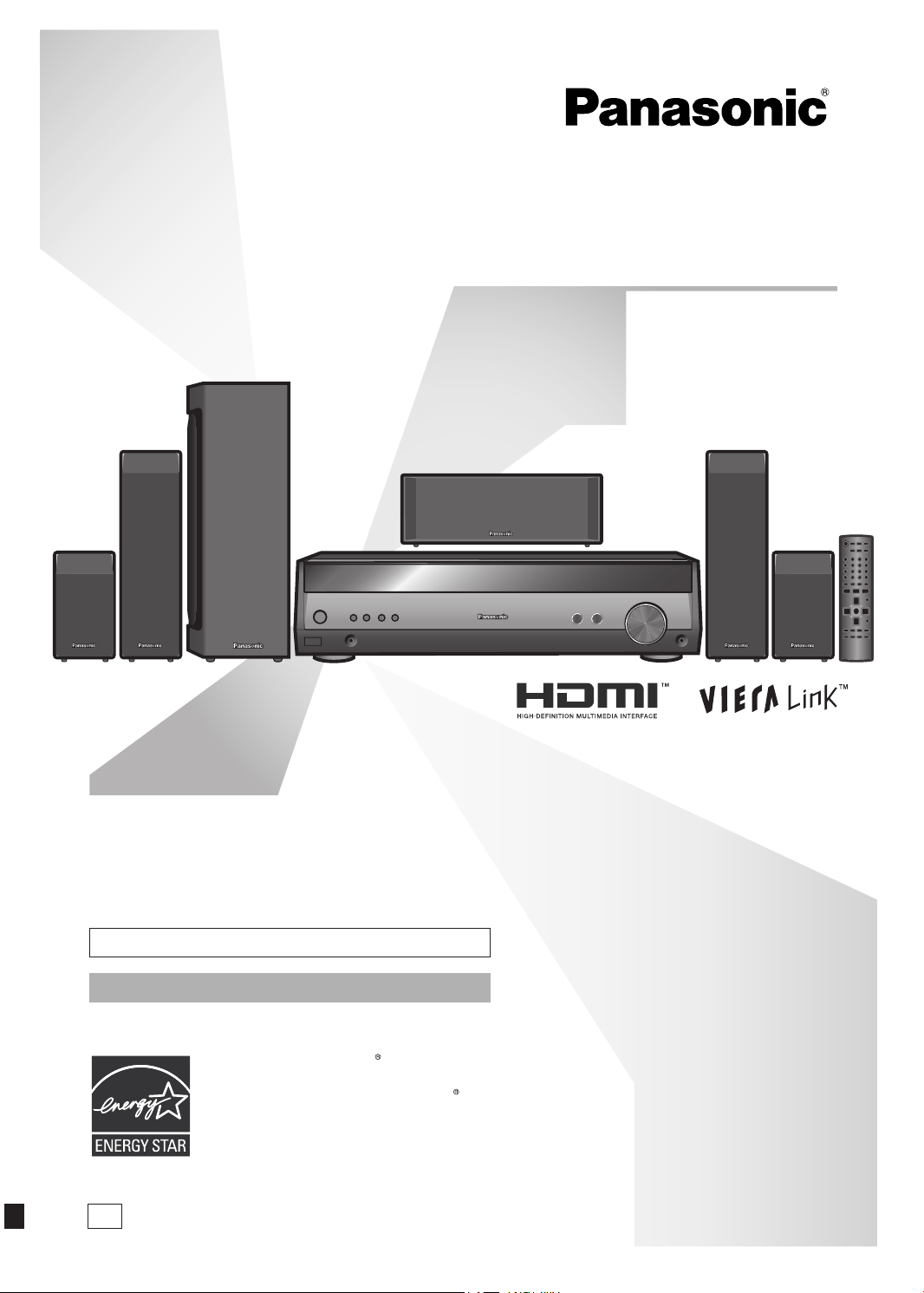
Operating Instructions
Home Theater Audio System
Model No.
SC-HT56
Dear customer
Thank you for purchasing this product.
Before connecting, operating or adjusting this
product, please read the instructions completely.
Please keep this manual for future reference.
If you have any questions contact 1-800-211-PANA (7262)
The warranty can be found on page 23.
A s an EN ER G Y S T A R Pa rt n er ,
Pa na so nic ha s de te rmined that this
pr o duc t mee ts th e ENE RGY STAR
guidelines for energy efficiency.
P
RQTX0175-2P
Page 2
2
RQTX0175
IMPORTANT SAFETY INSTRUCTIONS
these operating instructions carefully before using the unit. Follow the safety instructions on the unit and the applicable safety
Read
instructions listed below. Keep these operating instructions handy for future reference.
1) Read these instructions.
2) Keep these instructions.
3) Heed all warnings.
4) Follow all instructions.
5) Do not use this apparatus near water.
6) Clean only with dry cloth.
7) Do not block any ventilation openings. Install in accordance
with the manufacturer’s instructions.
8) Do not install near any heat sources such as radiators, heat
registers, stoves, or other apparatus (including amplifiers)
that produce heat.
9) Do not def ea t the saf ety pur po se of the p ola ri zed or
grounding-type plug. A polarized plug has two blades with
one wider than the other. A grounding-type plug has two
blades and a third grounding prong. The wide blade or the
third prong are provided for your safety. If the provided
plug does not fit into your outlet, consult an electrician for
replacement of the obsolete outlet.
IMPORTANT SAFETY INSTRUCTIONS
FCC Note:
This equipment has been tested and found to comply with the
limits for a Class B digital device, pursuant to Part 15 of the
FCC Rules.
These limits are designed to provide reasonable protection
against harmful interference in a residential installation. This
equipment generates, uses and can radiate radio frequency
energy and, if not installed and used in accordance with
the instructions, may cause harmful interference to radio
co mmuni ca tions . Howeve r, t here is no guaran te e that
interference will not occur in a particular installation. If this
equipment d oe s cause ha rmful interfer en ce to r ad io or
television reception, which can be determined by turning the
equipment off and on, the user is encouraged to try to correct
the interference by one or more of the following measures:
Reorient or relocate the receiving antenna.
Increase the se pa ration between t he equi pm ent and
receiver.
Connect the equipment into an outlet on a circuit different
from that to which the receiver is connected.
Consult the dealer or an experienced radio/TV technician
for help.
unauthorized changes or modifications to this equipment
Any
would void the user’s authority to operate this device.
Th is devi ce com pli es wit h Par t 15 of the F CC Rules.
Operation is subject to the following two conditions: (1) This
device may not cause harmful interference, and (2) this device
must accept any interference received, including interference
that may cause undesired operation.
Responsible Party:
Panasonic Corporation of North America
One Panasonic Way
Secaucus, NJ 07094
Support Contact:
Panasonic Consumer Electronics Company
Telephone No.: 1-800-211-PANA (7262)
Protect the power cord from being walked on or pinched
10)
particularly at plugs, convenience receptacles, and the point
where they exit from the apparatus.
11)
On ly use atta chm ent s/a cce sso rie s spe cif ied b y the
manufacturer.
12) Use only with the cart, stand, tripod,
bracket, or table specified by the
manufacturer, or sold with the apparatus.
When a cart is used, use caution when
moving the cart/apparatus combination to
avoid injury from tip-over.
13) Unplug this apparatus during lightning storms or when
unused for long periods of time.
14) Refer all servicing to qualified service personnel. Servicing
is required when the apparatus has been damaged in any
way, such as power-supply cord or plug is damaged, liquid
has been spilled or objects have fallen into the apparatus,
the apparatus has been exposed to rain or moisture, does
not operate normally, or has been dropped.
CAUTION: TO REDUCE THE RISK OF ELECTRIC
WARNING:
TO REDUCE THE RISK OF FIRE, ELECTRIC SHOCK OR
PRODUCT DAMAGE,
DO NOT EXPOSE THIS APPARATUS TO RAIN,
•
MOISTURE, DRIPPING OR SPLASHING AND THAT NO
OBJECTS FILLED WITH LIQUIDS, SUCH AS VASES,
SHALL BE PLACED ON THE APPARATUS.
USE ONLY THE RECOMMENDED ACCESSORIES.
•
DO NOT REMOVE THE COVER (OR BACK); THERE
•
ARE NO USER SERVICEABLE PARTS INSIDE. REFER
SERVICING TO QUALIFIED SERVICE PERSONNEL.
CAUTION
RISK OF ELECTRIC SHOCK
DO NOT OPEN
SHOCK, DO NOT REMOVE SCREWS.
NO USER-SERVICEABLE PARTS INSIDE.
REFER SERVICING TO QUALIFIED
SERVICE PERSONNEL.
The lightning flash with arrowhead symbol,
within an equilateral triangle, is intended to
alert the user to the presence of uninsulated
“dangerous voltage” within the product’s
enclosure that may be of sufficient magnitude
to constitute a risk of electric shock to persons.
The exclamation point within an equilateral
triangle is intended to alert the user to the
presence of important operating and
maintenance (servicing) instructions in the
literature accompanying the appliance.
Page 3
3
RQTX0175
System SC-HT56
EST. 192 4
AV Control Receiver SA-HT56
Front speakers SB-HF56
Surround speakers SB-HS760
Center speaker SB-HC760
Subwoofer SB-HWX50
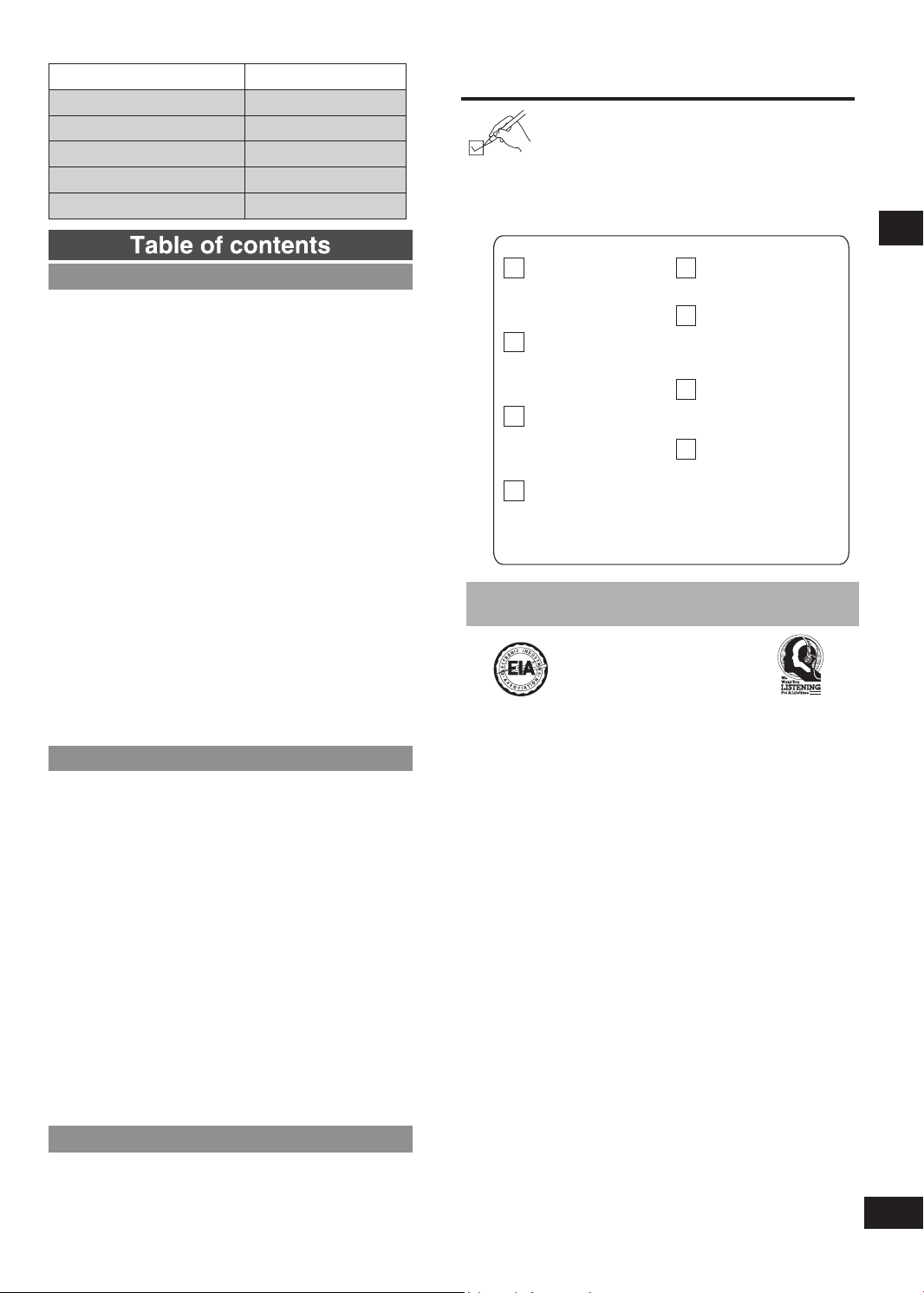
Supplied accessories
Please check and identify the supplied accessories.
Use numbers indicated in parentheses when
asking for replacement parts.
(Product numbers correct as of September 2008.
These may be subject to change.)
To order accessories, refer to “Accessory
Purchases” on page 23.
Table of contents
Before use
IMPORTANT SAFETY INSTRUCTIONS .......................... 2
Supplied accessories ...................................................... 3
Listening caution ............................................................. 3
The remote control .......................................................... 4
Control guide ................................................................... 4
Remote control ............................................................4
Main unit/Display ......................................................... 5
STEP 1 Speaker setup ....................................................6
Placement of speakers ................................................ 6
Connect the speakers to the receiver ........................ 6
Other speaker setup options ...................................... 7
Wireless system connection ......................................7
STEP 2 Home theater connections ............................... 8
HDMI and VIERA Link “HDAVI Control
High-quality audio and video simply with HDMI
connection ....................................................................8
Using the VIERA Link “HDAVI Control” ........................ 8
TV, BD player/DVD recorder and DVD player ............9
STEP 3 Antenna and AC power supply connections .......10
STEP 4 Auto speaker setup ......................................... 11
Process for auto speaker setup ............................... 11
Troubleshooting for auto speaker setup ................. 12
Settings ..........................................................................13
Distance/Auto setup/Input mode ..............................13
HDMI settings/DRCOMP/Attenuator/TV delay/
Adjusting speaker output level ................................14
Operations
Basic operations ............................................................15
Adding surround effects to stereo sources ............ 15
Using Dolby Pro Logic
Using the Sound Field Control (SFC) ......................... 15
MENU operation .............................................................16
The radio ........................................................................17
Direct tuning/Automatic presetting/Manual
presetting/Selecting channels .................................. 17
Sound field
Adjusting the tone/Dimension Control “DIMEN”/
Center Width Control “C-WDTH”/Balance/
Center focus/Adjusting SFC ..................................... 18
Other functions .............................................................. 19
Sleep timer/Muting/Dimmer ...................................... 19
The RESET function ...................................................... 19
Remote control operation guide .................................. 20
Watching DVDs/TV ....................................................20
Operating the DVD recorder/DVD player ................. 20
Operating the TV ........................................................ 20
Changing the remote control code .......................... 21
..................................................................... 18
............................................ 15
ΙΙ
Reference
Specifications ................................................................ 21
Troubleshooting guide ..................................................22
Maintenance ................................................................... 22
Limited Warranty ........................................................... 23
Product Service ..............................................Back cover
TM
” ................. 8
1 AC power
supply cord
(K2CB2CB00021)
1 FM indoor
antenna
(RSA0007-L1)
1 AM loop
antenna
(N1D
AAAA00002)
1 Speaker
sticker sheet
(RQCXA0013-1)
2 Batteries
1 Calibration
microphone
(L0CBAB000125)
1 Remote control
YB000319)
(N2QA
Speaker cables
3.0 m/9.8 ft. x 2
(REEX0449K-2K)
3.0 m/9.8 ft. x 1
(REEX0449K-2M)
8.0 m/26.2 ft. x 2
(REEX0449E-2K)
Listening caution
Selecting fine audio equipment such as the unit you’ve just
purchased
time to consider how you can maximize the fun and excitement
your equipment offers. This manufacturer and the Electronic
Industries Association’s Consumer Electronics Group want you
to get the most out of your equipment by playing it at a safe level.
One that lets the sound come through loud and clear without
annoying blaring or distortion-and, most importantly, without
affecting your sensitive hearing.
We recommend that you avoid prolonged exposure to excessive
noise.
Sound can be deceiving. Over time your hearing “comfort level”
adapts to higher volumes of sound. So what sounds “normal” can
actually be loud and harmful to your hearing.
Guard against this by setting your equipment at a safe level
BEFORE your hearing adapts.
To establish a safe level:
Start your volume control at a low setting.
•
S
•
and clearly, and without distortion.
Once you have established a comfortable sound level:
Set the dial and leave it there.
•
Taking a minute to do this now will help to prevent hearing
damage
lifetime.
is only the start of your musical enjoyment. Now it’s
lowly increase the sound until you can hear it comfortably
or loss in the future. After all, we want you listening for a
Supplied accessories/Listening caution
Page 4
4
RQTX0175
3
2
2
1
The remote control
R6/LR6, AA
g Batteries
Insert so the poles (+ and –) match those in the remote
•
control.
Do not use rechargeable type batteries.
•
Do not heat or expose to flame.
•
Do not leave the batteries in an automobile exposed to direct
•
sunlight for a long period of time with doors and windows
closed.
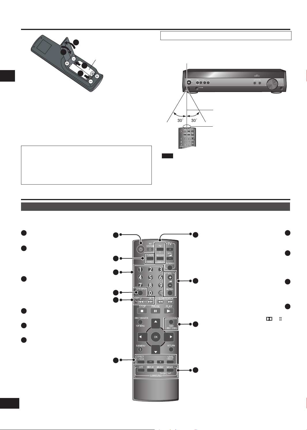
Use
Aim at the sensor, avoiding obstacles, at a maximum range of
7 m (23 feet) directly in front of the unit.
Remote control signal sensor
7 meters (23 feet)
Transmission window
CAUTION
Danger of explosion if battery is incorrectly replaced.
Replace only with the same or equivalent type
The remote control/Control guide
recommended by the manufacturer.
Dispose of used batteries according to the manufacturer’s
instructions.
Control guide
Remote control
This page describes the buttons used to control this unit.
See the guide at pages 20 and 21 for the buttons that control other units.
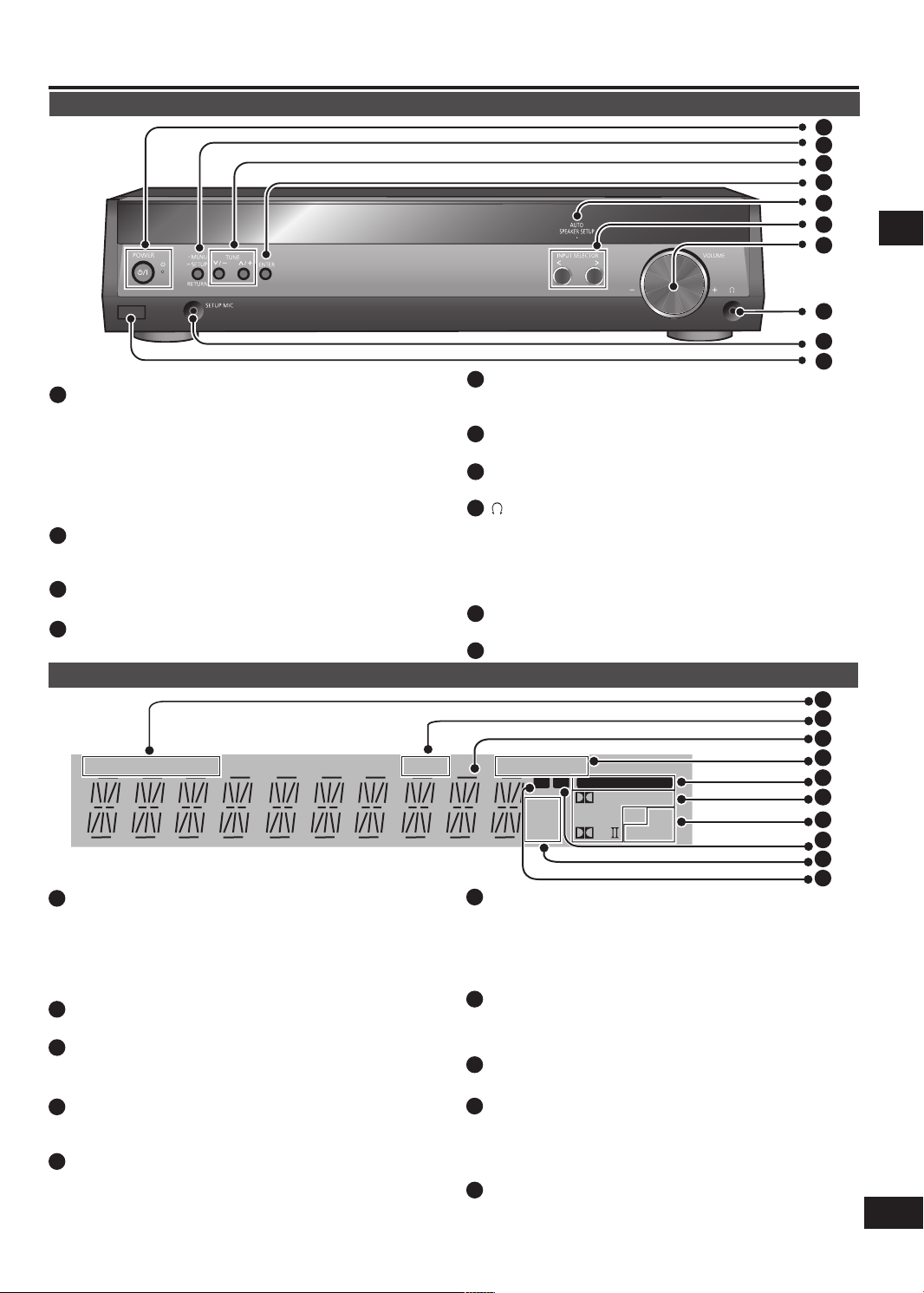
[^]
1
Standby/on button.
[TUNER, ―BAND]
2
For switching the remote c on tr ol to
TUNER mode and selecting TUNER.
After selecting TUNER, press and hold
to switch between FM and AM.
[1, 2, 3, 4, 5, 6, 7, 8, 9, 0]
3
To enter radio frequencies and
channels.
[≧10]
To enter two digit channels.
[-AUTO SETUP]
4
For auto speaker setup.
[u, 2, i, 1, SKIP]
5
For selecting preset radio channels.
[-EFFECT, ―C.FOCUS]
6
Use when adjusting Dolby Pro Logic ΙΙ
effects.
Press and hold to select center focus
mode.
[-, +]
Fi rs t sel ec t [- EFFECT] or [ -LEVEL,
—
TEST], then press [-] or [+] to adjust.
[-LEVEL, ―TEST]
Use when adjusting speaker level.
Press and hold to start the speaker test
signal.
1
2
3
4
5
6
Note
•
Keep the transmission window and the unit's sensor free from
dust.
peration can be affected by strong light sources, such as
•
O
direct sunlight, and the glass doors on cabinets.
―
7
Input mode and remote control mode
8
To enable selection of radio stations by
To cancel Dolby Pro Logic
9
For selecting a Dolby Pro Logic ΙΙ mode:
LIVE, POP/ROCK, VOCAL, JAZZ,
10
DRAMA, ACTION, SPORTS, MUSICAL,
[TV] [BD/DVR,
To adjust the volume.
To mute the volume.
[TUNER DIRECT TUNING]
MOVIE, MUSIC or PANORAMA.
For selecting SFC modes:
DANCE or PARTY.
For selecting SFC modes:
GAME or MONO.
DVD-P]
buttons.
[+, -, VOL]
[MUTING]
frequency.
[OFF]
and SFC.
ΙΙ
[
PL
[MUSIC]
[MOVIE]
7
8
9
10
]
Page 5
5
RQTX0175
Control guide
TUNED
MONO
SLEEP
PCM
ST
kHz
ft
MHz
DIGITAL DTS
2CH MIX
SFC
M
C.FOCUS
DIGITAL INPUT
PL
W
Main unit
1
2
3
4
5
6
7
8
Standby indicator [^]
1
When the unit is connected to the AC power supply, this
indicator lights up in standby mode and goes out when the
unit is turned on.
[8, POWER]
Press to switch the unit from on to standby mode or vice
versa. In standby mode, the unit is still consuming a small
amount of power.
[-MENU, ―SETUP, RETURN]
2
For entering menus and setup to make various settings.
•
For returning to previous menus.
•
[TUNE, 2 / 3, 1 / 4]
3
For tuning the radio and selecting menu or setup items.
[ENTER]
4
Used during menu or setup operations.
Display
[TUNED, ST, MONO]
1
Radio indicators
TUNED: A station is tuned
ST: A stereo FM broadcast is tuned
MONO: You have switched to monaural mode to improve
reception
[SLEEP]
2
Sleep timer indicator.
General display
3
S
hows the input mode, radio frequency and other general
information.
[PCM, C.FOCUS]
4
PCM: Lights when the PCMFIX mode is set
C.FOCUS: Appears when you are using Center Focus
[DIGITAL INPUT]
5
Lights when input is digital.
[AUTO SPEAKER SETUP]
5
Flashes during Auto Speaker Setup. Lights when the setup
finishes.
[INPUT SELECTOR, <, >]
6
For selecting input.
[VOLUME]
7
Volume control.
[ ] Headphone jack
8
Plug type:
•
Ø
3.5 mm (1/8") stereo
Sound does not come from the speakers if you connect
headphones.
Avoid listening for prolonged periods of time to prevent
•
hearing damage.
[SETUP MIC] jack
9
For calibration microphone.
Remote control signal sensor
10
6
[ % DIGITAL, DTS, % PLΙΙ]
Lights to indicate the source's input signal and decoding
format used.
DIGITAL: Dolby Digital sources
%
DTS: DTS sources
PLΙΙ: Dolby Pro Logic
%
[SFC, 2CH MIX]
7
decoder is being used
ΙΙ
SFC: Appears when you are using an SFC mode
2CH MIX: Appears when you are listening to a multi-channel
[M]
8
source with headphones
Flashes or lights during presetting.
[ft, kHz, MHz]
9
Distance and frequency unit indicators
ft: feet (speaker distance)
kHz: AM, or PCM sampling frequency
MHz: FM
[W]
10
Lights when you are using the digital transmitter (➡ page 7).
Flashes when there is no link between the main unit and
the wi reless system (Fo r details, refer to the o perating
instructions for SH-FX67).
9
10
1
2
3
4
5
6
7
8
9
10
Control guide
Page 6
6
RQTX0175
3
3
3
3
DNUORRUS
hcL
hcL
hc
L
DNU
ORRUS
hcL
DNUORRU
S
DNUORRU
S
4
4
4
4
DNUORRUS
hcR
hcR
hcR
D
NUORRU
S
hcR
DNUORRU
S
DNUORRU
S
6
6
REFOO
W
BU
S
BUS
REFOO
W
6
6
REFOOW
BUS
B
US
REFOO
W
1
1
1
1
hc
L
hcL
hcL
TNORF
T
N
ORF
TNORF
5
5
R
ETNEC
RET
N
E
C
5
5
RETNEC
RET
N
E
C
hc
L
TNOR
F
2
2
2
2
hc
R
hcR
hcR
TNORF
TNOR
F
TNOR
F
hcR
TNORF
Speaker setup
SUB
WOOFER
6
Lch
SURROUND
Lch
SURROUND
3
3
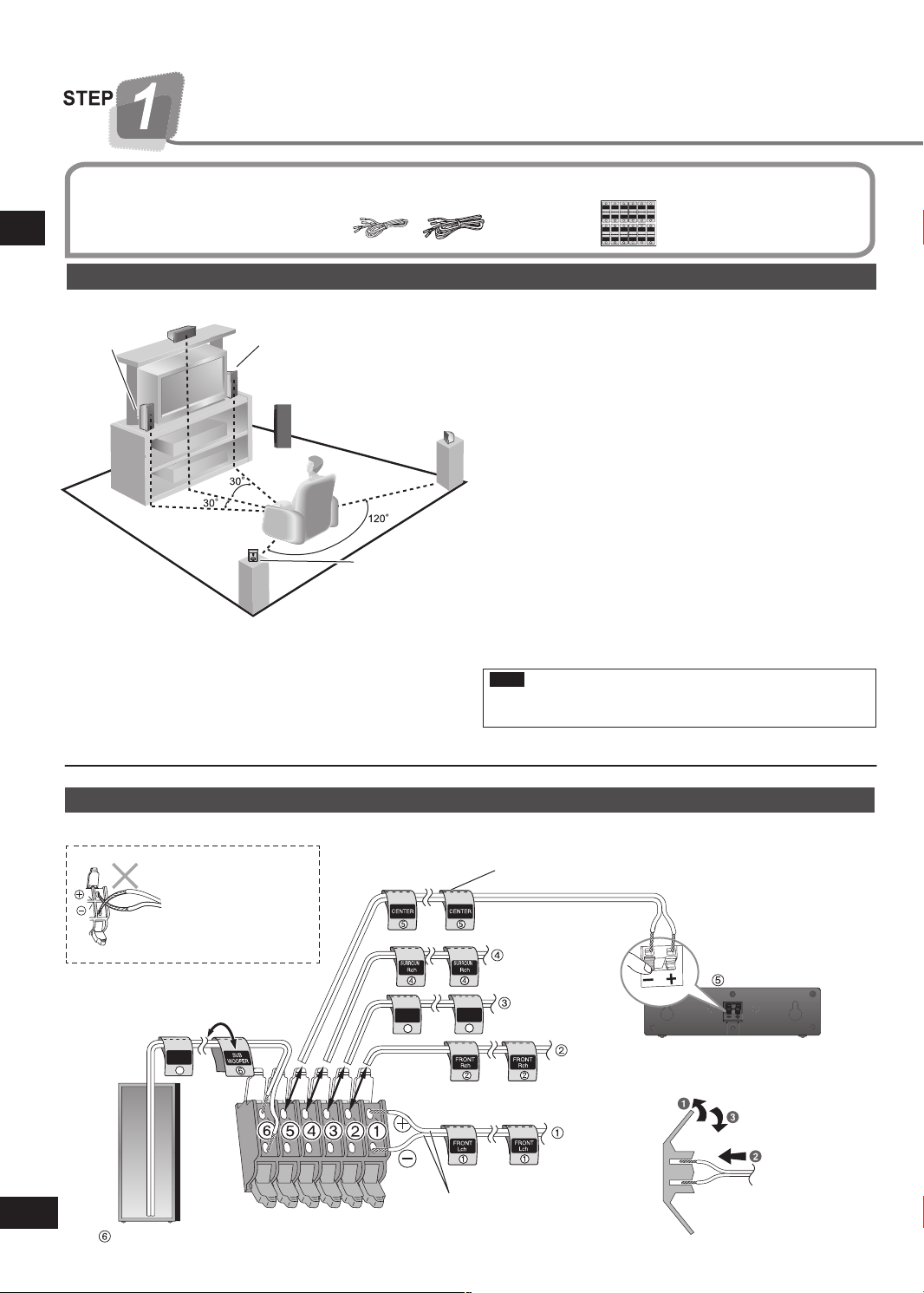
SUBWOOFER
CENTER
+: White
−: White (Blue line)
FRONT (R)
FRONT (L)
SURROUND (L)
SURROUND (R)
Push!
Speaker cables
Supplied
(3 short, 2 long)
accessories
Placement of speakers.
Placement of speakers
Front
Center speaker
speaker
Speaker setup STEP 1
(L)
Positioning for best effect
How you set up your speakers can affect the bass and the
sound field.
Note the following points.
Place speakers on flat secure bases.
•
Placing speakers too close to floors, walls, and corners can
•
result in excessive bass. Cover walls and windows with a
thick curtain.
Front
speaker
(R)
Subwoofer
Surround
speaker
(L)
Surround
speaker
(R)
1
Speaker sticker sheet
Place the front, center, and surround speakers at approximately
the same distance from the seating position.
Auto Speaker Setup compensates for any differences
(➡ pages 11 to 12).
The angles in the diagram are approximate.
Front speakers (left, right)
Place
on the left and right of the TV at seated ear height so that
there is good coherency between the picture and sound.
Center speaker
Place underneath or ab ove the center of the TV . A im the
speaker at the seating area.
Surround speakers (left, right)
Place on the side of or slightly behind the seating area, higher
than ear level.
Subwoofer
The subwoofer can be placed in any position as long as it is at a
reasonable distance from the TV.
Note that some experimentation can yield the smoothest low
frequency performance. Placement near a corner can increase
the apparent output level, but can result in unnatural bass.
Note
Keep your speakers at least 10 mm (13/
"
) away from the
32
system for proper ventilation.
Connect the speakers to the receiver
Attach the speaker-cable stickers to make connection easier.
Be careful not to
cross (short-circuit)
o
r reverse the polarity
of the speaker wires
as doing so may
damage the speakers.
Speaker-cable sticker
Insert the wire fully.
not insert the
Do
wires beyond the
wire insulation.
Page 7
7
RQTX0175
1 2
PUSH PUSH
Digital transmitter cover
Rear panel of the main unit
TRANSMITTER
DIGITAL
PUSH PUSH
Push!Push!
Turn off all components before making any connections.
•
Peripheral equipment and cables sold separately
•
unless otherwise indicated.
To connect equipment, refer to the appropriate
•
operating instructions.
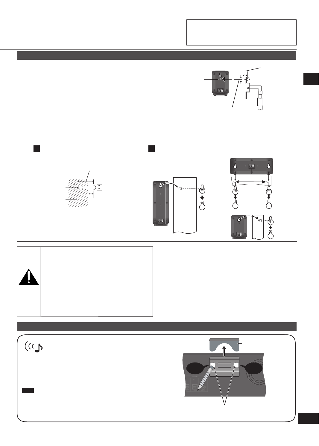
Other speaker setup options
■
Fitting optional speaker stands
(For front, center and surround speakers)
Ensure the stands meet these conditions before purchasing them.
N
ote the diameter and length of the screws and the distance between
screws as shown in the diagram.
The stands must be able to support over 10 kg (22 lb.).
•
The stands must be stable even if the speakers are in a high position.
•
■
Attaching to a wall
Example: Surround speaker
Metal screw
hole
F
or attaching
to speaker
stands.
3
5.0 mm (
/16"), pitch 0.8 mm (1/32")
You can attach the surround, center and front speakers to a wall.
The wall or pillar on which the speakers are to be attached should be capable of supporting 10 kg
•
(22 lb.) per screw. Consult a
qualified building contractor when attaching the speakers to a wall. Improper attachment may result in damage to the wall and
speakers.
Drive the screw (not included) into the wall Fit the speaker securely onto the screw(s) with the hole(s)
Center speaker
At least 30 mm (1
3
/16")
Front speakers
Plate thickness plus
7.0 mm (
10 mm (
Speaker stand
(not included)
9
/32") to
13
/32")
STEP 1 Speaker setup
Ø4.0 mm (5/32")
Wall or pillar
Ø7.0 mm (
to 9.4 mm (
4.0 mm (
to 6.0 mm (
5
/32")
1
/4")
Caution
Use the speakers only with the recommended
•
syste m. Failure to do so can damag e the
amplifier and speakers, and can cause fire.
Consult a qualified service person if damage
occurs or if a sudden change in performance
is apparent.
Do not at te mp t to attach t he se speakers
•
to wa ll s using methods other t han thos e
described in this manual.
Wireless system connection
Set your sound free with Panasonic’s wireless
Attach the SH-FX67 digital transmitter for wireless surround sound.
You can also connect your portable audio equipment to the wireless
system.
For details, refer to the operating instructions for SH-FX67.
Note
Rem ove the digital transmitter cover bef ore installing any optional
Panasonic wireless accessory.
Replace the cover when the digital transmitter is not in use.•
receiver and speaker systems
9
/32")
11
/32")
190 mm
15
/32")
(7
Surround speaker
If irregular coloring occurs on your television
The supplied speakers are designed to be used close to a
television, but the picture may be affected with some televisions
and setup combinations.
If this occurs, turn the television off for about 30 minutes.
The television's demagnetizing function should correct the
problem. If it persists, move the speakers further away from the
television.
Notes on front speakers
These speakers do not have magnetic shielding. Do not place
them near televisions, personal computers or other devices
easily influenced by magnetism.
You can use the blunt end of a writing instrument
to push here until the cover pops out.
Page 8
8
RQTX0175
INPUT SELECTOR
TUNE
MENU
RETURN
SETUP
SETUP MIC
VOLUME
ENTER
INPUT SELECTOR
TUNE
MENU
RETURN
S
ETUP
SETUP MIC
VOLUME
ENTER
Home theater connections
TRA NSMITTER
DIGITAL
PUSH PUSH
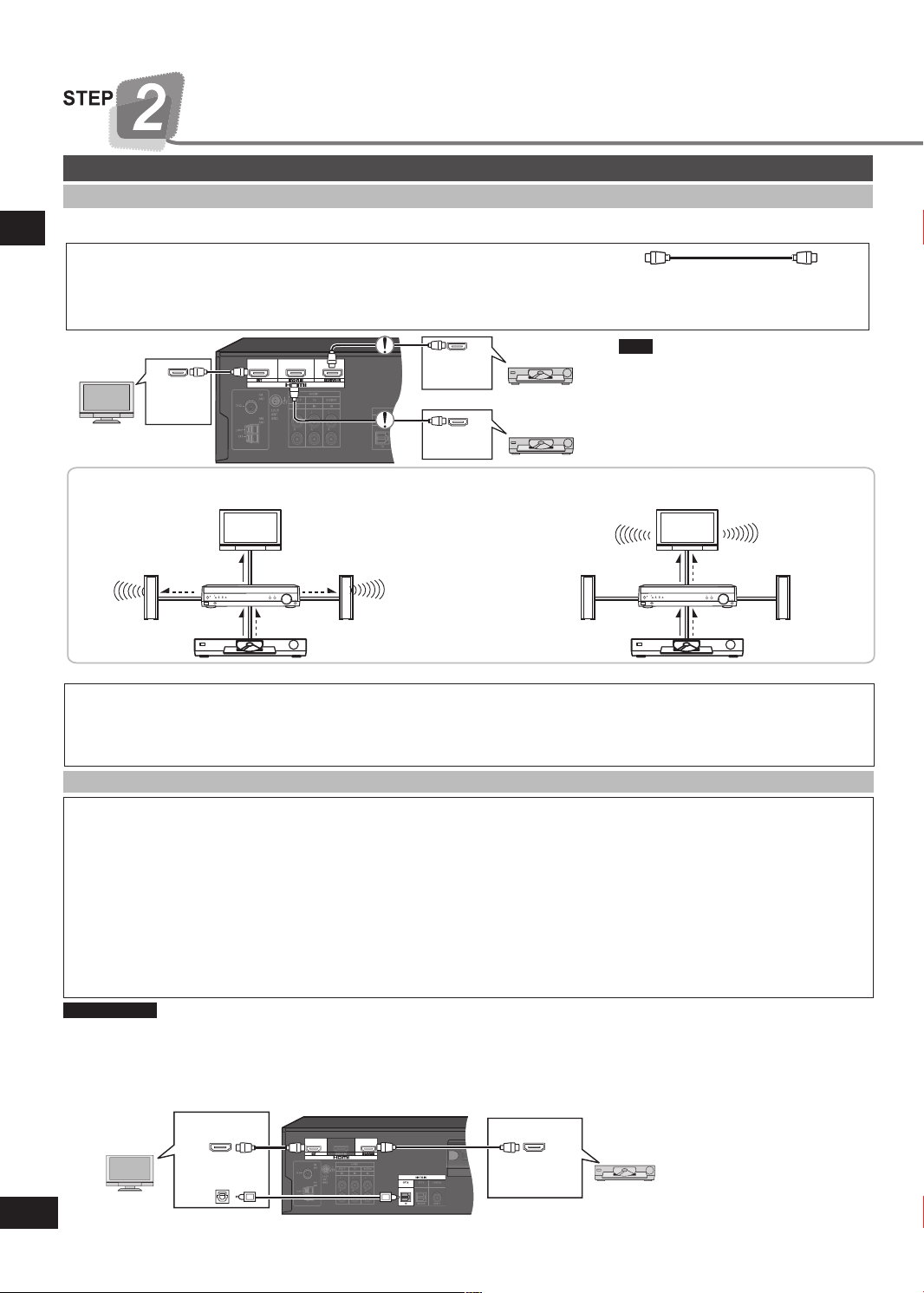
HDMI and VIERA Link “HDAVI ControlTM”
High-quality audio and video simply with HDMI connection
STEP 2
The HDMI (High Definition Multimedia Interface) connection means you only need one cable to transmit digital audio and video
•
between two pieces of equipment.
HDMI Cable (not included) (Use a Panasonic HDMI cable for best results.)
It is recommended that you use Panasonic’s HDMI cable.
•
Recommended part number: RP-CDHG10 (1.0 m/3.3 ft.), RP-CDHG15 (1.5 m/4.9 ft.), RP-CDHG20 (2.0 m/6.6 ft.),
Non-HDMI-compliant cables cannot be utilized.
•
Rear panel
TV HDMI
V IN)
(A
Home theater connections
Audio and video signal flow when you have used HDMI connections
The audio and video signals from DVD equipment pass through to the television even if this unit is set to standby.
When this
unit is on
Video
Video A
For your reference
Audio signals from HDMI connection takes priority to digital terminal connections (➡ page 9).
•
This unit’s HDMI can carry video signals up to 1125p (1080p) (even when this unit is in standby mode).
•
1125p: a progressive (non-interlace) scanning system that sends 1,125 scan lines every 1/60 second.
Please use High Speed HDMI Cables that have the HDMI logo (as shown on the cover).
•
When outputting 1080p signal, please use the HDMI cables 16.4 feet or less.
•
Using the VIERA Link “HDAVI Control”
What is VIERA Link “HDAVI Control” ?
VIERA LinkTM is a new name for EZ SyncTM.
VIERA Link “HDAVI Control” is a convenient function that offers linked operations of this system, and a Panasonic TV
(VIERA) or DVD recorder (DIGA) under “HDAVI Control”. You can use this function by connecting the equipment with the
HDMI cable. See the operating instructions for connected equipment for operational details.
VIERA Link “HDAVI Control”, based on the control functions provided by HDMI which is an industry standard known as HDMI
•
CEC (Consumer Electronics Control), is a unique function that we have developed and added. As such, its operation with other
manufacturers’ equipment that supports HDMI CEC cannot be guaranteed.
This system supports “HDAVI Control 2” function.
•
“HDAVI Control 2” is the newest standard (current as of February, 2007) for Panasonic’s HDAVI Control compatible equipment.
This standard is compatible with Panasonic’s conventional HDAVI equipment.
Please refer to individual manuals for other manufacturers’ equipment supporting VIERA Link function.
•
Preparation
1. Connect your other Panasonic home theater equipment (VIERA Link “HDAVI Control” compatible VIERA television or
DIGA DVD recorder) with an HDMI cable (above).
2. Read your television’s operating instructions and make the settings necessary to activate the VIERA Link “HDAVI Control”.
3. Switch on all your equipment, then switch your television off then on again and check that images from DIGA appear
correctly. (Do this whenever you change connections or settings.)
TV HDMI
TV (VIERA)
(A
DIGITAL AUDIO
OUT (OPTICAL)
RP-CDHG30 (3.0 m/9.8 ft.), RP-CDHG50 (5.0 m/16.4 ft.), etc.
BD player/
DVD recorder
DVD player
When this unit is in
TV
DVD HDMI
(AV OUT)
DVD HDMI
(AV OUT)
standby mode
(in standby ON
condition, ➡ page 14)
A
udioAudio
This unit
udio
Speakers
DVD equipment
Rear panel
V IN)
VD HDMI
D
(A
V OUT)
Note
Connect only DVD equipment to
the HDMI input terminal of the unit.
Connecting other equipment may
prevent the output of sounds or show
distorted pictures.
TV
Video A
DVD recorder
(DIGA)
udio
This unit
AudioVideo
DVD equipment
Speaker
s
To take advantage of the multi-channel sounds now available with digital television, use a digital connection if your TV has a
•
digital output terminal.
To turn off VIERA Link “HDAVI Control”, “HDMI settings”, ➡ page 14.
•
Page 9

9
RQTX0175
TRA N SMITTER
DIGITAL
PUSH PUSH
NSMITTER
DIGITAL
TRA N SMITTER
DIGITAL
PUSH PUSH
DIGITAL AUDIO
OUT
VIDEO OUT
VIDEO IN
AUDIO OUT
VIDEO IN
VIDEO OUT
OPT 2
BD/DVR
DVD-P
L
R
IN
L
R
BD/DVR
IN
FRONT (L, R)
AUDIO OUT
DIGITAL AUDIO
OUT
AUDIO OUT
L
TV
R
IN
OPT 1
TV
TV
DVD player
TV (Monitor)
TV (Monitor)
R
DIGITAL AUDIO
OUT
COAXIAL
DVD-P
Coaxial
DVD player
Turn off all components before making any connections.
•
Peripheral equipment and cables sold separately
•
unless otherwise indicated.
To connect equipment, refer to the appropriate
•
operating instructions.
Other
accessories
Left
Right
Notes on digital input
Stereo connection cable
This unit can decode the following signals:
Dolby Digital, DTS
•
PCM, including PCM with sampling frequencies of 96 kHz
•
or 88.2 kHz
It cannot decode:
Other digital signals, such as MPEG
•
Dolby Digital RF signals from a laser disc player
•
TV, BD player/DVD recorder and DVD player
Optical fiber cable
Note
•
Use digital connection to enjoy Dolby Digital or DTS.
•
Do not bend the optical fiber cable.
•
Coaxial cable
BD player/
DVD recorder
Connect the
video cable
directly to the
TV.
STEP 2
Home theater connections
Connect the
video cable
directly to
the TV.
Page 10

10
RQTX0175
TRA N SMITTER
DIGITAL
PUSH PUSH
2
3
1
1
2
AC IN
~
AC IN
~
Supplied
accessories
Antenna and AC power
supply connections
Turn off all components before making any connections.
•
Peripheral equipment and cables sold separately
•
unless otherwise indicated.
To connect equipment, refer to the appropriate
•
operating instructions.
AM loop antenna1 FM indoor antenna 1 AC power supply cord
1
FM indoor antenna
Antenna and AC power supply connections STEP 3
Adhesive tape
Fix the end of the antenna where
reception is best.
Black
White
For best reception
FM outdoor antenna
Disconnect the FM indoor
•
antenna.
The an t enna sh o uld be
•
instal le d by a co mp et en t
technician.
Red
Keep the antenna cord away from DVD players and other cords.
75 Ω coaxial cable
AM loop antenna
FM outdoor antenna
Antenna plug
Click!
The cooling fan operates at high power output levels only.
AC power supply cord
C
onnect this cord after all other cables
are connected.
Household AC outlet
(AC 120 V/60 Hz)
Conserving power
he unit consumes 0.7 W (in HDMI standby on condition) even when it is turned off with [8]
T
To save power when the unit is not to be used for a long time, unplug it from the household AC
outlet. You will need to reset some memory items after plugging in the unit.
Note
The included AC power supply cord is for use with this unit only. Do not use it with other
•
equipment.
Do not use an AC power supply cord from other equipment.
•
.
Page 11

11
RQTX0175
Turn off all components before making any connections.
•
Peripheral equipment and cables sold separately
•
unless otherwise indicated.
To connect equipment, refer to the appropriate
Auto speaker setup
Auto speaker setup allows you to achieve a satisfactory listening environment easily with the use of the supplied calibration microphone
as a detector of sound signals. The unit will first perform automatic speaker detection, then checks and adjusts the following settings.
•
operating instructions.
STEP 4Auto speaker setup
DETECTION
DISTANCE
LEVEL
Loud test tones are output from the speakers during setup, so keep children out of the room.
Before setup
Conduct the auto speaker setup in a quiet environment. A noisy background will give unsatisfactory results.
Checks which speakers you have connected.•
ks the distance of each speaker from the listening position and adjusts the
•
Chec
timing of each channel automatically.
es any further corrections to the frequency response.•FREQUENCY
Mak
Chec
ks and adjusts each speaker level automatically.•
Process for auto speaker setup
Turn on the unit.
Press
.
The standby indicator goes off when you turn on the unit.•
Connect the calibration
microphone to the
[SETUP MIC] jack on
the front panel.
Placing of calibration
microphone.
Note
The calibration microphone is sensitive to
heat. Keep it away from direct sunlight and
do not place it on top of the unit.
Calibration microphone
(included)
P
lace on a flat surface at the seating area.
•
Set calibration microphone position at
•
your ear height.
Page 12

12
RQTX0175
-AUTO SETUP
AUTO
SPEAKER SETUP
AUTO
SPEAKER SETUP
Auto speaker setup
-AUTO SETUP
-AUTO SETUP
Turn off all components before making any connections.
•
Peripheral equipment and cables sold separately
•
unless otherwise indicated.
To connect equipment, refer to the appropriate
•
operating instructions.
STEP 4
Start performing auto
speaker setup.
Auto speaker setup
Auto speaker setup finishes.
To cancel during setup
Press any button on the main unit or remote control. “CANCELED” appears on the display.
Note
Perform auto speaker setup again if you have changed the speakers, speaker positions, or the layout of your listening
•
environment.
If you find speaker output unsatisfactory, reset all auto speaker setup settings and change them manually. Refer to “Auto setup”
•
(➡ page 13).
The calibration will give optimal result for “DISTANCE”. Therefore, you are unable to adjust the setting manually.
•
a) Press and hold .
[AUTO SPEAKER SETUP] indicator starts flashing.
•
“AUTO SETUP” appears on the display.
•
b) The unit checks that you have correctly
connected the calibration microphone.
c) The automatic setup starts with STEP 1, STEP 2,
and STEP 3 calibration as follows.
STEP1 – DETECTION/DISTANCE STEP2 – FREQUENCY STEP3 – LEVEL
For your reference
Loud test tones are output from each speaker during the configuration.
•
During setup, operations may stop when there is an error message on the display.
•
Refer below for troubleshooting.
“COMPLETE” appears on the display and all calibrations are saved.
•
[A
UTO SPEAKER SETUP] indicator lights.
•
To exit, press and hold .
•
Disconnect the calibration microphone.
•
While performing auto speaker setup, errors may occur and the messages will blink or scroll on the display, depending on the
conditions. Press any button on the main unit or remote control to stop the setup.
After troubleshooting, press and hold to start the setup process again.
“INSERT MIC” Calibr
“CHECK CONNECTION TO
LS/RS SPEAKERS”
“CHECK CONNECTION TO
L/R SPEAKERS”
Note
•
Auto speaker setup may produce an unsatisfactory result with some speaker setups and configurations.
•
Auto speaker setup will not start if you have muted the speakers. Turn the muting off (➡ page 19).
Auto speaker setup will not start if you have plugged in headphone. Unplug any headphone.
•
VIERA Link “HDAVI Control
•
Troubleshooting for auto speaker setup
Message Solutions Pages
ation microphone is not detected. Insert the microphone correctly.• 11
One of the surround speakers is not detected. Check the connections.• 6
k the front (L) and (R) connections.• 6
Chec
TM
” (➡ page 8) is disab
led during auto speaker setup.
Page 13

13
RQTX0175
Settings
Change the settings to suit your equipment
to the environment in which you are using
it. Before making any changes, read the
descriptions of the settings, note the factory
settings and ranges, and refer to the
equipment's instructions.
Display
Switch on.
Enter the
1
setup mode.
Select the item you want to change.
2
Select and press [ENTER].
2a
Change the
3
setting.
Exit the
4
setup mode.
DISTANCE ↔ AUTO SETUP ↔ INPUT
MODE ↔ HDMI ↔ DRCOMP ↔
ATTENUATOR ↔ REMOTE ↔ TV DELAY ↔
Press to change the
setting.
P
ress r e p e a t e d l y
until “EXIT” appears.
RESET ↔ EXIT
efer to pages 13 and 14 for each item settings.
•
Press and hold.
Note
Auto speaker setup calibration will give optimal result for “DISTANCE”. Therefore, you are unable to adjust the setting manually.
•
Distance
Cha nge the distanc e so that the sound from all the speakers (except for the
subwoofer) reaches you at the same time.
You can select distances between 3 feet and 30 feet.
The factory settings are:
Enter
the seating position.
R
For “REMOTE”, refer to page 21.
•
For “RESET”, refer to page 19.
•
Select and press [ENTER].
2b
the distance of the front, center and surround speakers from
LR (front):
C (center):
S (surround):
10 ft (feet)
10 ft (feet)
5 ft (feet)
Press once to enter.
2a 2b
DISTANCE LR
C
S
Repeat for each speaker channel
Press [ENTER] to
completely exit the
setup mode.
3 feet to
30 feet
Settings
3
Auto setup
YES: Reset all auto speaker setup settings
NO: To cancel (factory setting)
Input mode
AUTO: The unit automatically detects whether input is digital or analog.
(factory setting)
ANALOG: Select to make the unit accept analog input.
DIG: Select to make the unit accept digital input.
PCMFIX1: Select to input to PCM.
1
In rare cases, the unit may have trouble recognizing PCM signals and this may cause the beginning of tracks to be cut off.
Select “PCMFIX” if this occurs.
With DTS, the signals may not be recognized at all. Engage the DTS FIX mode if this occurs.
•
To engage the DTS FIX mode:
Press and hold [-MENU] and [ENTER] at the same time. “DTS” lights.
To cancel the DTS FIX mode:
Press and hold [-MENU] and [ENTER] at the same time.
The mode cancels when input mode is set to AUTO or when the unit is turned off.
Note
When a FIX mode is on, the unit cannot process other signals. This may cause noise to be output. If this occurs, select an
input mode other than PCMFIX, or cancel the DTS FIX mode.
Reset the settings done in auto speaker setup.•
This unit automatically detects whether input is digital or
•
analog, but you can fix the input mode.
UTO SETUP DEFAULT NO
A
INPUT MODE TV
DVR
DVD
(continue on next page)
YES
AUTO
ANALOG
DIG
PCMFIX
Page 14

14
RQTX0175
VOL
C +4dB
L C R RS LS SUBW
TEST
L
VOL
Settings
Display
Switch on.
To reduce standby power consumption.
HDMI settings
Standby selection
OFF: Standby power consumption reduced
Settings
(approximately 0.3 W).
Signals from DVD equipment cannot pass
•
through HDMI connection to the television
when the unit is in standby (➡ page 8).
VIERA Link “HDAVI Control” (➡ page 8)
•
does not work when the unit is in standby.
ON: Normal standb y powe r cons um ption
(factory setting)
DRCOMP
OFF: The software is played with the original dynamic range (factory setting).
STANDARD: The level recommended by the producer of the software for household
viewing.
MAX: The maximum allowable compression (recommended for night viewing).
Attenuator
•
Choice for turning off the VIERA Link “HDAVI ControlTM”
•
(➡ page 8).
VIERA Link “HDAVI Control”
OFF: VIERA Link “HDAVI Control”
is OFF
ON: VIERA Link “HDAVI Control”
is ON (factory setting)
(Dynamic range compression)
Change this setting to listen to software recorded with Dolby
•
Digital at low volume (such as late at night) and maintain audio
clarity. It reduces the peak level in loud scenes without affecting
the sound field.
(A/D Attenuator)
Turn the A/D attenuator on if “OVERFLOW” lights frequently
•
when using 2-channel analog input. The factory setting is OFF.
2a 2b
HDMI STNBY
DRCOMP OFF
ATTENUATOR OFF
CTRL
STANDARD
MAX
ON
3
OFF
ON
Delay audio if there appears to be a difference in timing between
TV delay
•
audio and pictures. The factory setting is ON.
Adjusting speaker output level
Output the signal. Adjust the main
volume.
Press and hold.
TV DELAY OFF
ON
C (center), RS (surround right) and LS (surround left) can be adjusted between -6 dB and
+6 dB, with 0 dB being the level of the front speakers. Adjust center and surround output to
the same apparent level of the front speakers.
For SUBW (subwoofer), you can select “SUBW OFF” so there is no output, “SUBW MIN”
for minimum output, a level between 1 and 19, or “SUBW MAX” for maximum output. Adjust
subwoofer output so it is balanced with the front speakers.
Select the speaker
channel.
Adjust the level. Stop the test
signal.
Press and hold.
Repeat for each speaker channel
Page 15

15
RQTX0175
Basic operations
TUNER FM TVTUNER AM
BD/DVR
D
VD-P
1 2 3 4
PL
MUSIC
MOVIE
PL
Start play of the
Switch on.
Select input.
Adding surround effects to stereo sources
source.
The unit sets the sound
mode to suit the input
signal.
Adjust the
volume.
Basic operations
Using Dolby Pro Logic
Dolby Pro Logic ΙΙ processor works not only on
sources recorded with Dolby Surround, but also
on any stereo source.
Press to select a mode from the table at
right.
To cancel, press [OFF].
•
You can make fine surround settings when in the
MUSIC or PANORAMA mode. (➡ page 18)
Using the Sound Field Control (SFC)
En joy an enhanc ed sou nd exp eri en ce wit h
greater presence and spread by using these SFC
modes with PCM or analog stereo sources.
Press to select a mode from the
tables at right.
To cancel, press [OFF].
•
You can change the speaker level of SFC.
(➡ page 18)
Note
Dolby Pro Logic ΙΙ and SFC modes remain in
•
effect until you turn the mode off.
When input is PCM with sampling frequencies
•
of 96 kHz or 88.2 kHz, you cannot add
surround effects with Dolby Pro Logic ΙΙ or
SFC.
When input is Dolby Digital or DTS, you can
•
use SFC.
ΙΙ
MOVIE
Use this mode when playing movie software recorded in Dolby
Surround.
MUSIC
Adds surround effects to stereo sources.
PANORAMA
ound is spread out more so you feel like you are surrounded by
S
music.
LIVE
Brings you up close for “live” stage performance and smoother
vocals.
POP/ROCK
For pop, rock, and other music that has a punch to it.
VOCAL
For adding gloss to vocals.
JAZZ
Conveys the exciting and intimate atmosphere of a jazz club.
DANCE
For dance music and other sounds with a strong beat.
PARTY
mode uses the front and surround speakers so that sound is in
This
stereo regardless of the direction you are facing.
DRAMA
For dramas and other material where dialog is important.
ACTION
For action movies and other material where impact is important.
SPORTS
To make you feel like you were in the stadium.
MUSICAL
For musicals and other material where music is important.
GAME
Enjoy gaming with more impact.
MONO
For monaural sound.
Page 16

16
RQTX0175
MENU operation
T U N E R F M M O D E
M E M O RY
AU TO M EM O
T U N E M O D E
B E AT P R O O F M O D E 1
M O D E 2
AU TO
E X I T
E X I T
M O N O
M E M O C H 1
M E M O C H 3 0
S TA R T
C A N C E L
M A N UAL
P R E S E T
B A S S 0
T R E B L E 0
B A L A N C E
D I M M E R O F F D I M M E R O F F
D I M M E R 1
D I M M E R 2
D I M M E R 3
S L E E P O F F
B A S S - 6
B A S S + 6
T R E B L E - 6
T R E B L E + 6
S L E E P O F F
S L E E P 3 0
S L E E P 6 0
S L E E P 9 0
S L E E P 1 2 0
L R
2
1
3
4 5
This is an outline of the operations you can perform with
the MENU.
Press [-MENU] once.
Main menu Sub menu 1 Sub menu 2 Exit
Display
The radio ➡ page 17
MENU operation
Adjust the bass ➡ page 18
Adjust the treble ➡ page 18
You
the front speakers ➡ page 18
D
im the disp l ay for bett e r
viewing in a darkened room
page 19
➡
can adjust the balance of
(TUNER FM only)
(TUNER AM only)
Press
repeatedly
until “EXIT”
appears.
Press
repeatedly
until “EXIT”
appears.
Press
[ENTER] to
completely
exit the
m
enu mode.
Press
[ENTER] to
completely
exit the
m
enu mode.
The
SLEEP timer can turn the
unit off after a set time
page 19
➡
Page 17

17
RQTX0175
21
The radio
Press [INPUT SELECTOR < or >]
to select “TUNER FM” or “TUNER
AM”.
Direct tuning
Input the frequency of the station.
Remote control
1. Press [TUNER,
2. Press and hold [TUNER
―
BAND] to select “TUNER”.
―
BAND] to select “TUNER
,
FM” or “TUNER AM”.
3.
Press [TUNER DIRECT TUNING].
4. Press the numbered buttons to enter the
frequency.
e.g. To select 107.9 MHz, press [1] → [0] → [7] → [9]
If you do not press a button while the cursor is flashing, the
•
display returns to the frequency being received.
If the frequency has not been input correctly, “ERROR” will be
•
displayed.
Automatic presetting
The FM stations the unit can receive are preset in channels 1 to
30. The AM stations the unit can receive are preset in channels
21 to 30 (FM stations are replaced if any were preset in these
channels).
Preparation: Tune to either FM 87.9 MHz or AM 530 kHz.
Main unit
1. Press [-MENU] to select “TUNER” ➡ “AUTO
MEMO”.
2.
Press [TUNE 2 / - or 1 / +] to select “START”
[ENTER].
➡
Select “CANCEL” to cancel.
The tuner presets all the stations it can receive into the channels
in ascending order.
During automatic presetting, the memory indicator (M) flashes
and the frequency scrolls. The memory indicator and channel
numbers are displayed for a second when a station is preset.
The last station to be preset is displaye d when presetti ng
finishes.
Select the frequency.
Auto tuning starts if you press and
hold the button.
Manual presetting
Preset the stations one at a time.
Preparation: Tune to the station you want to preset.
Main unit
1. Press [-MENU] to select “TUNER” ➡ “MEMORY”.
2. Press [TUNE 2 / - or 1 / +] to select the channel
[ENTER].
➡
(“STORED” lights.)
For your reference
FM stations can also be preset in the MONO mode.
Selecting channels
Remote control
1. Press [TUNER,
2. Press
or
Press the numbered buttons.
For channels 1 to 9, press the corresponding number.
For channels 10 or over, press [≧10], then the two digits.
e.g. To select channel 21: [≧10] → [2] → [1]
Main unit
[SKIP u,
1. Press [-MENU] to select “TUNER” ➡ “TUNE
MODE”.
2.
Press [TUNE 2 / - or 1 / +] to select “PRESET”
[ENTER].
➡
Select “MANUAL” to cancel.
3. After exiting the menu:
Press [TUNE 2 / - or 1 / +].
―
BAND] to select “TUNER”.
i,
2
or
1
].
The radio
Reducing excessive noise
During FM stereo reception During AM reception
You c an im pr ove FM receptio n by switching receptio n to
monaural.
Main unit
1. Press [-MENU] to select “TUNER” ➡ “FM MODE”.
2. Press [TUNE 2 / - or 1 / +] to select “MONO”
➡
[ENTER].
Select “AUTO” to cancel.
When there is a lot of noise interference with an AM broadcast,
try switching this mode.
Main unit
1. Press [-MENU] to select “TUNER” ➡ “BEAT
PROOF”.
2. Press [TUNE 2 / - or 1 / +] to select “MODE 1” or
“MODE 2”
➡
[ENTER].
Page 18

Sound field
MUSIC MOVIE
SFC
-EFFECT
C.FOCUS
-LEVEL
TEST
OK
VOLUME
TOP MENU
FUNCTIONS
TUNER
DIRECT TUNING
DIRECT NAVIGATOR
SUB MENU
RETURN
SUBWOOFER
708
9
10
4 5
6
>
=
u
q
g h
SKIP
SLOW/SEARCH
STOP PAUSE PLAY
t y
i
-/ - -
SURROUND
PLOFF
S
-EFFECT
C.FOCUS
-LEVEL
TEST
Sound field
Adjusting the tone
You can adjust the level of the bass and treble.
Main unit
1. Use the menus to select “BASS” or “TREBLE”.
MENU operation on page 16.
➡
2.
Press [TUNE 2 / - or 1 / +] to adjust the tone.
Input signals must be either analog or PCM, and Dolby Pro
Logic ΙΙ and SFC must be off (
page 15)
➡
.
Dimension Control “DIMEN”
can adjust the effect of the Dolby Pro Logic ΙΙ
You
PANORAMA modes (➡ page 15).
can make up for differences in the output level of the front
You
and surround speakers.
You can choose a level between -3 and +3: Increase the level
to move sound to the front speakers, decrease to move it to the
surround speakers.
The factory setting is 0.
Remote control
1. Press [-EFFECT, ―C.FOCUS] to select “DIMEN”.
2. Press [-] or [+] to adjust the effect.
Center Width Control “C-WDTH”
You can adjust the effect of the Dolby Pro Logic ΙΙ
PANORAMA modes (➡ page 15).
adjustment helps you realize a more natural sound image
This
when listening to music. Move sound out into the front speakers
to improve the overall front image, or add sound to the center
speaker to fix the center image.
You ca n choose a level between 0 (the center speaker is
dominant) and 7 (center sound is spread out).
The factory setting is 3.
Remote control
1. Press [-EFFECT, ―C.FOCUS] to select “C-WDTH”.
RQTX0175
2. Press [-] or [+] to adjust the effect.
18
MUSIC and
MUSIC and
Balance
You can adjust the balance of the front speakers.
Main unit
1. Use the menus to select “BALANCE”.
MENU operation on page 16.
➡
2.
Press [TUNE 2 / - or 1 / +] to adjust the balance.
Center focus
Use with discs where the dialogue is recorded in the center
channel.
You can make the sound of the center speaker seem like it is
coming from within the television.
Remote control
Press and hold [-EFFECT, ―C.FOCUS].
“C.FOCUS” lights.
The factory setting is off.
You cannot use this when the sound mode is STEREO.
Adjusting SFC
You can adjust the sound field by adjusting the level of the
speakers. This adjustment can be made for each SFC mode
(➡ page 15).
Remote control
1. Press [-LEVEL, ―TEST] to select the speaker
channel.
Each time you press the button:
C → RS → LS → SUBW
2. Press [-] or [+] to adjust the level.
C, RS, and LS: -6 dB to +6 dB
SUBW: OFF ↔ MIN ↔ 1 - 19 ↔ MAX
Page 19

Other functions
Sleep timer
The SLEEP timer can turn the unit off after a set time.
It does not control any other components.
Main unit
1. Use the menus to select “SLEEP”.
MENU operation on page 16.
➡
2.
Press [TUNE 2 / - or 1 / +] to select the time
(in minutes).
The display changes as follows:
SL EEP OFF ↔
SLEEP 120
↔
To check the setting
1. Press [-MENU] to enter the main menu.
2. Press [TUNE 2 / - or 1 / +] to select “SLEEP”.
The time remaining appears.
To change the setting
Repeat the procedure from the beginning.
SLEEP 30 ↔ SLEEP 60 ↔ SLEEP 90
The RESET function
Muting
Remote control
Press [MUTING].
To cancel
Press [MUTING] again.
Muting also cancels when you adjust the volume or switch the
unit to standby.
Dimmer
Dim the display for better viewing in a darkened room.
Main unit
1. Use the menus to select “DIMMER”.
MENU operation on page 16.
➡
2.
Press [TUNE 2 / - or 1 / +] to select the level
(1, 2, or 3) or OFF.
Other functions/The RESET function
The operation settings for the unit will be initialized to the settings made at the time of shipment.
However, any preset radio stations will not be erased.
1. Press and hold [―SETUP] to enter the setup menu.
2. Press [TUNE 2 / - or 1 / +] to select “RESET” ➡ [ENTER].
3.
Press [TUNE 1 /+] to select “RESET YES” ➡ [ENTER].
To cancel, select “RESET NO”.
RQTX0175
19
Page 20

20
RQTX0175
Remote control operation guide
MEN U
MENU
MEN U
^
^
^ ^
DIRECT NAVIGATOR
FUNCTIONS
TUNER
DIRECT TUNING
RETURN
STOP
PAUSE
PAUSE
PAUSE
SKIP
SLOW/SEARCH
SLOW/SEARCH
This remote control can operate Panasonic DVD recorders, DVD players, and televisions.
Note that this remote control cannot operate some equipment and that it may not be able to perform some operations.
Before using a Panasonic DVD recorder or player
DVD recorder
Change the remote control code to match the remote control mode of the DVD recorder.
1. Check the remote control mode of the DVD recorder.
2. For about one second hold down both [OK] and the numbered button ([1], [2] or [3]) (the same as the remote control mode of the
DVD recorder).
The factory setting is [1].
DVD player
Change the remote control code so you can operate a DVD player.
For about one second hold down both [OK] and [4].
Watching DVDs/TV
Switch on
Switch on the television and select input
Switch on the player and start play
Remote control operation guide
Switch off
Operating the DVD recorder/DVD player
Show disc menus
Show disc menus
elect and enter
S
menu items
Show player menus
C
Stop play Pause play
lear menus or return
to previous menus
Operating the TV
S
tart play from a
selected item
Start slow-motion play
To view frame-by-frame
Skip items
during play
Search
through the
disc
Select channels directly
Adjust the volume
Page 21

21
RQTX0175
MENU
RETURN
SETUP
Remote control operation guide
Changing the remote control code
Change the code if you find the
remote control unintentionally also
controls other Panasonic equipment.
Do the following to set the remote
control code and this unit’s remote
control mode to the same one.
Change the main unit’s mode
1. Enter the SETUP menu.
Press and hold .
2. Select and press [ENTER].
3. Select and press [ENTER].
4. Press [-MENU, –SETUP, RETURN]
re pea tedly t o sel ec t “ EXI T” an d
press [ENTER].
Specifications (IHF’78)
AMPLIFIER SECTION
g
RMS Output Power of each channel driven
10 % total harmonic distortion
1 kHz Front CH 125 W per channel (3 Ω)
1 kHz Surround CH 125 W per channel (3 Ω)
1 kHz Center CH 250 W per channel (6 Ω)
100 Hz Subwoofer CH 250 W per channel (6 Ω)
Total RMS Output Power 1000 W
Rated minimum sine wave RMS power output
1% total harmonic distortion (Dolby Digital mode)
120 Hz to 20 kHz Front CH 53 W per channel (3 Ω)
120 Hz to 20 kHz Surround CH 53 W per channel (3 Ω)
120 Hz to 20 kHz Center CH 133 W per channel (6 Ω)
45 Hz to 120 Hz Subwoofer CH 141 W per channel (6 Ω)
Total FTC Output Power 486 W
Rated minimum sine wave RMS power output
1% total harmonic distortion (Stereo mode)
120 Hz to 20 kHz Front CH 52 W per channel (3 Ω)
45 Hz to 150 Hz Subwoofer CH 141 W per channel (6 Ω)
Total FTC Output Power 245 W
Total harmonic distortion
half power at 1 kHz (Front CH) 0.5 % (3 Ω)
Input sensitivity
DVD-P, TV, BD/DVR 450 mV, IHF'66
S/N at rated power
DVD-P, TV, BD/DVR 80 dB
Input impedance
DVD-P, TV, BD/DVR 47 k
Tone controls
BASS 50 Hz, +6 dB to -6 dB
TREBLE 20 kHz, +6 dB to -6 dB
Digital input/output:
HDMI Input 2
HDMI Output 1
Optical digital input 2
Coaxial digital input 1
Analog input/output
Analog audio input 3
Wireless Ready SH-FX67
OPERATING CONDITION
g
Operating temperature range 0°C to +40°C (+32°F to +104°F)
Operating humidity range 20% to 80% RH (no condensation)
FM TUNER SECTION
g
Frequency range 87.9 MHz to 107.9 MHz
Sensitivity 11.2 dBf (2 µV), IHF'58
Total harmonic distortion
MONO 0.3%
STEREO 0.4%
S/N
MONO 64 dB
STEREO 63 dB
Antenna terminal 75 Ω (unbalanced)
AM TUNER SECTION
g
Frequency range 530 kHz to 1710 kHz
Change the remote control’s code
5. Press .
6. Whi le pres sin g , pre ss and
hold f
or about 2 seconds.
To restore the code to “1”
On the main unit: In step 3, select “1”.
•
On the remote control: In step 6, while
•
pressing [OK], press and hold [1] for about
2 seconds.
SPEAKER SECTION
g
Rating with low-cut filter equipped Amplifier
Front speaker
Type 1 Way, 1 Speaker
Speaker unit
Full range 6.5 cm (2
Input power (IEC) 125 W
Output sound pressure 80 dB/W (1.0 m)
Frequency range 86 Hz to 25 kHz (-16 dB)
98 Hz to 22 kHz (-10 dB)
Dimensions (W x H x D) 92 mm x 272 mm x 95 mm
(3
Weight 0.74 kg (1.6 lb.)
(SB-HF56)
5
/8" x 10 23/32" x 3 3/4")
Surround speaker (SB-HS760)
Type 1 Way, 1 Speaker
Speaker unit
Full range 6.5 cm (2
Input power (IEC) 125 W
Output sound pressure level 80 dB/W (1.0 m)
Frequency range 95 Hz to 25 kHz (-16 dB)
120 Hz to 22 kHz (-10 dB)
Dimensions (W x H x D) 92 mm x 142 mm x 95 mm
(3
Weight 0.6 kg (1.32 lb.)
5
/8" x 5 19/32" x 3 3/4")
Center speaker (SB-HC760)
Type 2 Way, 2 Speakers
Speaker unit
Ω
Full range 6.5 cm (2
Input power (IEC) 250 W
Output sound pressure level 82 dB/W (1.0 m)
Crossover frequency 5 kHz
Frequency range 80 Hz to 25 kHz (-16 dB)
96 Hz to 22 kHz (-10 dB)
Dimensions (W x H x D) 270 mm x 94 mm x 95 mm
(10
Weight 1.3 kg (2.9 lb.)
1
5
/8" x 3 11/16" x 3 3/4")
Subwoofer (SB-HWX50)
Type 1 Way, 1 Speaker
Speaker unit (Woofer) 16 cm (6
Input power IEC 250 W (Max/6
Output sound pressure level 78 dB/W (1.0 m)
Frequency range 35 Hz to 200 Hz (-16 dB)
40 Hz to 198 Hz (-10 dB)
Dimensions (W x H x D) 181 mm x 361 mm x 315 mm
(7
Weight 4.7 kg (10.4 lb.)
GENERAL
g
Power supply AC 120 V, 60 Hz
Power consumption 125 W
Dimensions (W x H x D) 430 mm x 105 mm x 388 mm
(16
Weight 4 kg (8.8 lb.)
Power consumption in standby mode:
HDMI On: 0.7 W
HDMI Off: 0.3 W
1
/8" x 14 7/32" x 12 13/32")
15
/16" x 4 1/8" x 15 9/32")
Notes:
1. Specifications are subject to change without notice.
Total harmonic distortion is measured by the digital spectrum analyzer.
2.
1
/2") cone type
(Max/3 Ω)
1
/2") cone type
(Max/3 Ω)
/2") cone type x 2
(Max/6 Ω)
1
/2") cone type
Ω)
Remote control operation guide/Specifications
Page 22

22
RQTX0175
Troubleshooting guide
Before requesting service, make the following checks. If you are in doubt about any of the check points, or if the remedies indicated
in the chart do not solve the problem, refer to “Customer Services Directory” on page 23.
Common problems
■
No power. Ensure the AC power supply cord is connected.• 10
No sound.
Display is dim.
“OVERLOAD”, “F70”, or “F76”
appears on the display.
“FAN LOCK” appears on the
display.
Sound
■
Sound is not heard from the
center, surround, or subwoofer
speakers.
A ticking noise interrupts the
sound.
Cannot use Dolby Pro Logic
or SFC.
Radio
■
The radio cannot be tuned in
or there is a lot of noise and
interference.
There is a lot of noise when
Troubleshooting guide/Maintenance
listening to AM.
HDMI
■
When using an HDMI
connection, the first few
seconds of sound is cut off.
“U 70-1-1” appears on the
display.
“U 70-1-2” appears on the
display.
“U 70-3” appears on the
display.
The unit does not work
properly.
VIERA Link “HDAVI Control
does not function properly.
Remote control
■
The remote control does not
work.
Other products respond to the
remote control.
Page
T
urn the volume up.
•
Check connections to speakers and other equipment.
•
Select the correct source.
•
Check that the digital signals can be decoded by this unit.
•
Turn PCMFIX and DTS FIX off.
•
An electrostatic discharge (ESD) may interrupt sound. Turn the unit off and on again.
•
k the DIMMER level.
•
Chec
An electrostatic discharge (ESD) may cause the display to dim. Turn the unit off and on again.
•
urn the unit off, disconnect the AC power supply cord, and consult your dealer.• –
T
ve the object obstructing the cooling fan.• –
Remo
The source ma
The speak
II
Y
ou cannot use Dolby Pro Logic II or SFC when input is PCM with sampling frequencies of 96 kHz
•
or 88.2 kHz.
Connect the appropr
•
Adjust the position of the FM or AM antenna.
•
Reduce the treb
•
Turn off nearby televisions, video decks and DVD players.
•
Separate the antenna from other cables, leads, and appliances.
•
Try changing the sound mode or turning the modes off.
•
ry changing the BEAT PROOF mode.• 16, 17
T
Should y
•
– Change the audio output setting on the DVD player or DVD recorder from “Bitstream” to “PCM”.
(6.1-channel sources will however be played as 5.1-channel.)
– Select “PCMFIX” as instructed in “INPUT MODE” when you play 2-channel sources.
•
The equipment connected b
technology.
•
The unit has receiv
Check the settings of the connected equipment.
Should an
•
Consult your dealer if the sign remains on the display after these steps.
– Turn the connected equipment off and on again.
– Pull out the HDMI cable then reinsert it.
– Reduce the amount of equipment connected in series to the HDMI terminal if exceeding 2 units.
he unit does not work properly when wrong cords are in HDMI input and output terminals. Turn the
•
T
unit off, unplug the AC power supply cord, and make connections again.
TM
•
”
Connect the unit to y
power supply cord, and insert it into a household AC outlet again.
Replace the batter
Change this unit’
y be stereo. Use Dolby Pro Logic
er wires are touching each other. Check all your speaker connections.• 6
iate antenna. (You may need an outdoor antenna or one with more elements.)
le.
ou be playing a chapter on a DVD:
y the HDMI cable is not compatible with the unit’s copyright protection
ed a signal for a picture format that is incompatible with the HDMI connection.
ything unusual happen using an HDMI connection:
our TV (VIERA) using the HDMI cable, switch the TV on, unplug the unit’s AC
ies if they are worn.• 4
s remote control code to “REMOTE 2”.• 21
II
or SFC
.•
15
6-10
15
9
13
–
19
–
15
15
10
10
16, 18
–
–
15
–
13
–
–
–
8
–
8
–
Maintenance
If the surfaces are dirty
To clean this unit, wipe with a soft, dry cloth.
Never use alcohol, paint thinner or benzine to clean this unit.
•
Before using chemically treated cloth, read the instructions that came with the cloth carefully.
•
Page 23

23
RQTX0175
Limited Warranty
Panasonic Consumer Electronics Company,
Division of Panasonic Corporation of North America
One Panasonic Way Secaucus, New Jersey 07094
Panasonic Audio Products
Limited Warranty
Limited Warranty Coverage
If your product does not work properly because of a defect in materials or
workmanship, Panasonic Consumer Electronics Company or Panasonic
Puerto Rico, Inc. (collectively referred to as “the warrantor”) will, for the
length of the period indicated on the chart below, which starts with the
date of original purchase (“warranty period”), at its option either (a) repair
your product with new or refurbished parts, or (b) replace it with a new or
a refurbished product. The decision to repair or replace will be made by
the warrantor.
Product or Part Name Parts Labor
Audio Products (except items listed
below)
USB Reader-Writer, Personal
Computer Card Adapters
(in exchange for defective item)
Accessories: Headphones, Cartridges,
Microphones, Adapters
Rechargeable Batteries, DVD-R/-RAM
Discs (in exchange for defective item)
SD Memory Cards, Rechargeable
Battery Packs (in exchange for
defective item)
uring the “Labor” warranty period there will be no charge for labor.
D
During the “Parts” warranty period, there will be no charge for parts. You
must carry-in or mail-in your product during the warranty period. If nonrechargeable batteries are included, they are not warranted. This warranty
only applies to products purchased and serviced in the United States or
Puerto Rico. This warranty is extended only to the original purchaser of a
new product which was not sold “as is”. A purchase receipt or other proof
of the original purchase date is required for warranty service.
Carry-In or Mail-In Service
Carry-In or Mail-In Service in the United States call 1-800-211-PANA
For
(1-800-211-7262) or visit Panasonic web site: http://www.panasonic.com
One (1) year
One (1) year
Ninety (90)
days
en (10) days
T
Ninety (90)
days
Customer Services Directory
Obtain Product Information and Operating Assistance; locate your nearest Dealer or Servicenter; purchase Parts and
Accessories; or make Customer Service and Literature requests by visiting our Web Site at:
h�p://www.panasonic.com/consumersupport
or, contact us via the web at:
h�p://www.panasonic.com/contactinfo
You may also contact us directly at:
1-800-211-PANA (7262),
Monday-Friday 9 am-9 pm; Saturday-Sunday 10 am-7 pm, EST.
For hearing or speech impaired TTY users, TTY: 1-877-833-8855
Accessory Purchases
Purchase Parts, Accessories and Instruction Books online for all Panasonic Products by visiting our Web Site at:
h�p://www.pstc.panasonic.com
or, send your request by E-mail to:
npcparts@us.panasonic.com
You may also contact us directly at:
1-800-332-5368 (Phone) 1-800-237-9080 (Fax Only) (Monday – Friday 9 am to 8 pm, EST.)
Panasonic Service and Technology Company
20421 84th Avenue South, Kent, WA 98032
(We Accept Visa, MasterCard, Discover Card, American Express, and Personal Checks)
For hearing or speech impaired TTY users, TTY: 1-866-605-1277
Service in Puerto Rico
Panasonic Puerto Rico, Inc.
Ave. 65 de Infantería, Km. 9.5, San Gabriel Industrial Park, Carolina, Puerto Rico 00985
Phone (787)750-4300, Fax (787)768-2910
One (1)
year
Not
Applicable
Ninety (90)
days
Not
Applicable
Not
Applicable
Panasonic Puerto Rico, Inc.
Ave. 65 de Infantería, Km. 9.5
San Gabriel Industrial Park, Carolina, Puerto Rico 00985
or ass is ta nc e in Pu er to Ric o call Pa na sonic Pu erto Ric o, Inc .
F
(787)-750-4300 or fax (787)-768-2910.
Limited Warranty Limits And Exclusions
his warranty ONL Y CO VERS failures due to def ects in materials
T
or workmansh ip, and DOES NOT CO VER normal wear and tear or
cosmetic damage. The warranty ALSO DOES NOT COVER damages
which occurred in shipment, or failures which are caused by products not
supplied by the warrantor, or failures which result from accidents, misuse,
abuse, neglect, mishandling, misapplication, alteration, faulty installation,
set -up adjustm ents, misad justment of con sumer controls, imp rop er
mai nte nan ce, power line surge, li ght nin g da mag e, modi fic ati on, or
commercial use (such as in a hotel, office, restaurant, or other business),
ren tal use of the product, service by anyon e ot her than a Fac tor y
Servicenter or other Authorized Servicer, or damage that is attributable to
acts of God.
HERE ARE NO EXPRE SS WARRA NTIES EX CEPT AS LIST ED
T
UNDER “LIMITED WARRANTY COVERAGE”. THE WARRANTOR IS
NOT LIABLE FOR INCIDENTAL OR CONSEQUENTIAL DAMAGES
RESULTING FROM THE USE OF THIS PRODUCT, OR ARISING OUT
OF ANY BREACH OF THIS WARRANTY. (As examples, this excludes
damages for lost time, travel to and from the servicer, loss of media or
images, data or other memory content. The items listed are not exclusive,
but are for illustration only.)
ALL EXPRESS AND IMPLIED WARRANTIES, INCLUDING THE WARRANTY
OF MERCHANTABILITY, ARE LIMITED TO THE PERIOD OF THE LIMITED
WARRANTY.
Some states do not allo w the exclusi on or limi tation of incidental or
consequential damages, or limitations on how long an implied warranty
lasts, so the exclusions may not apply to you. This warranty gives you
specific legal rights and you may also have other rights which vary from
state to state. If a problem wit h this product develops during or after
the warranty period, you may contact your dealer or Servicenter. If the
problem is not handled to your satisfaction, then write to the warrantor’s
Consumer Affairs Department at the addresses listed for the warrantor.
PARTS AND SERVICE WHICH ARE NOT COVERED BY THIS LIMITED
WARRANTY ARE YOUR RESPONSIBILITY.
Limited Warranty
Page 24

Product Service
Product information
1. Damage requiring service — The unit should be serviced by
qualified service personnel if:
(a ) The A C pow er sup ply c or d or the plu g has b een
damaged; or
(b) Objects or liquids have gotten into the unit; or
(c) The unit has been exposed to rain; or
(d) The unit does not operate normally or exhibits a marked
change in performance; or
(e) The unit has been dropped or the cabinet damaged.
2. Servicing — Do not attempt to service the unit beyond that
described in these operating instructions. Refer all other
servicing to authorized servicing personnel.
3. Replacement parts — When parts need replacing ensure
the servicer uses parts specified by the manufacturer or
parts that have the same characteristics as the original parts.
Unauthorized substitutes may result in fire, electric shock, or
other hazards.
4. Safety check — After repairs or service, ask the servicer to
perform safety checks to confirm that the unit is in proper
working condition.
The servicer will require all components to service your system.
Therefore, should service ever be necessary, be sure to bring
the entire system.
For product information or assistance with product operation,
refer to “Customer Services Directory” on page 23.
CAUTION!
DO NOT INSTALL OR PLACE THIS UNIT IN A BOOKCASE,
BUILT-IN CABINET OR IN ANOTHER CONFINED SPACE.
ENSURE THE UNIT IS WELL VENTILATED. TO PREVENT
RISK OF ELECTRIC SHOCK OR FIRE HAZARD DUE
TO OVERHEATING, ENSURE THAT CURTAINS AND
ANY OTHER MATERIALS DO NOT OBSTRUCT THE
VENTILATION VENTS.
CAUTION!
Do not place anything on top of this unit or block the heat
radiation vents in any way. In particular, do not place tape
decks or CD/DVD players on this unit as heat radiated from it
can damage your software.
The socket outlet shall be installed near the equipment and
easily accessible.
The mains plug of the power supply cord shall remain readily
operable.
To completely disconnect this apparatus from the AC Mains,
disconnect the power supply cord plug from AC receptacle.
Manufactured under license from Dolby Laboratories.
Dolby, Pro Logic, and the double-D symbol are trademarks of
Dolby Laboratories.
Manufactured under license under U.S. Patent #’s: 5,451,942;
5,956,674; 5,974,380; 5,978,762; 6,487,535 & other U.S. and
worldwide patents issued & pending. DTS and DTS Digital
Surround are registered trademarks and the DTS logos and
Symbol are trademarks of DTS, Inc. © 1996-2008 DTS, Inc.
All Rights Reserved.
The model number and serial number of this product can be
found on either the back or the bottom of the unit.
Please note them in the space provided below and keep for
future reference.
MODEL NUMBER __________________________________
SERIAL NUMBER __________________________________
SC-HT56
User memo:
DATE OF PURCHASE _____________________________
DEALER NAME __________________________________
DEALER ADDRESS _______________________________
______________________________________________________
TELEPHONE NUMBER ___________________________
Panasonic Consumer Electronics
Company, Division of Panasonic
Corporation of North America
One Panasonic Way Secaucus,
New Jersey 07094
http://www.panasonic.com
HDMI, the HDMI logo and High-Definition Multimedia
Interface are trademarks or registered trademarks of HDMI
Licensing LLC.
EZ Sync™ is a trademark of Panasonic Corporation.
VIERA LINK™ is a trademark of Panasonic Corporation.
HDAVI Control™ is a trademark of Panasonic Corporation.
-If you see this symbol-
Information on Disposal in other Countries outside the
_
European Union
_
Panasonic Puerto Rico, Inc.
Ave. 65 de Infantería, Km. 9.5
San Gabriel Industrial Park, Carolina,
Puerto Rico 00985
This symbol is only valid in the European Union.
If you wish to discard this product, please contact
your local authorities or dealer and ask for the correct
method of disposal.
En
© Panasonic Corporation 2008
Printed in Malaysia
RQTX0175-2P
H0908HU2118
 Loading...