

Page 1

Setup Guide
DVD Home Theater Sound System
STEP1 Positioning the speakers
STEP2 Speaker connections
STEP3 Digital transceiver connection
Operating Instructions
Model No. SC-HT545W
STEP4 Audio, video and radio connections
STEP5 AC mains lead connections
STEP6 Preparing the remote control
STEP7 Presetting the radio stations
STEP8 Performing QUICK SETUP
All necessary steps of setup are completed.
Please see the Operations Guide for playback operations.
EB
RQT8737-2B
Page 2
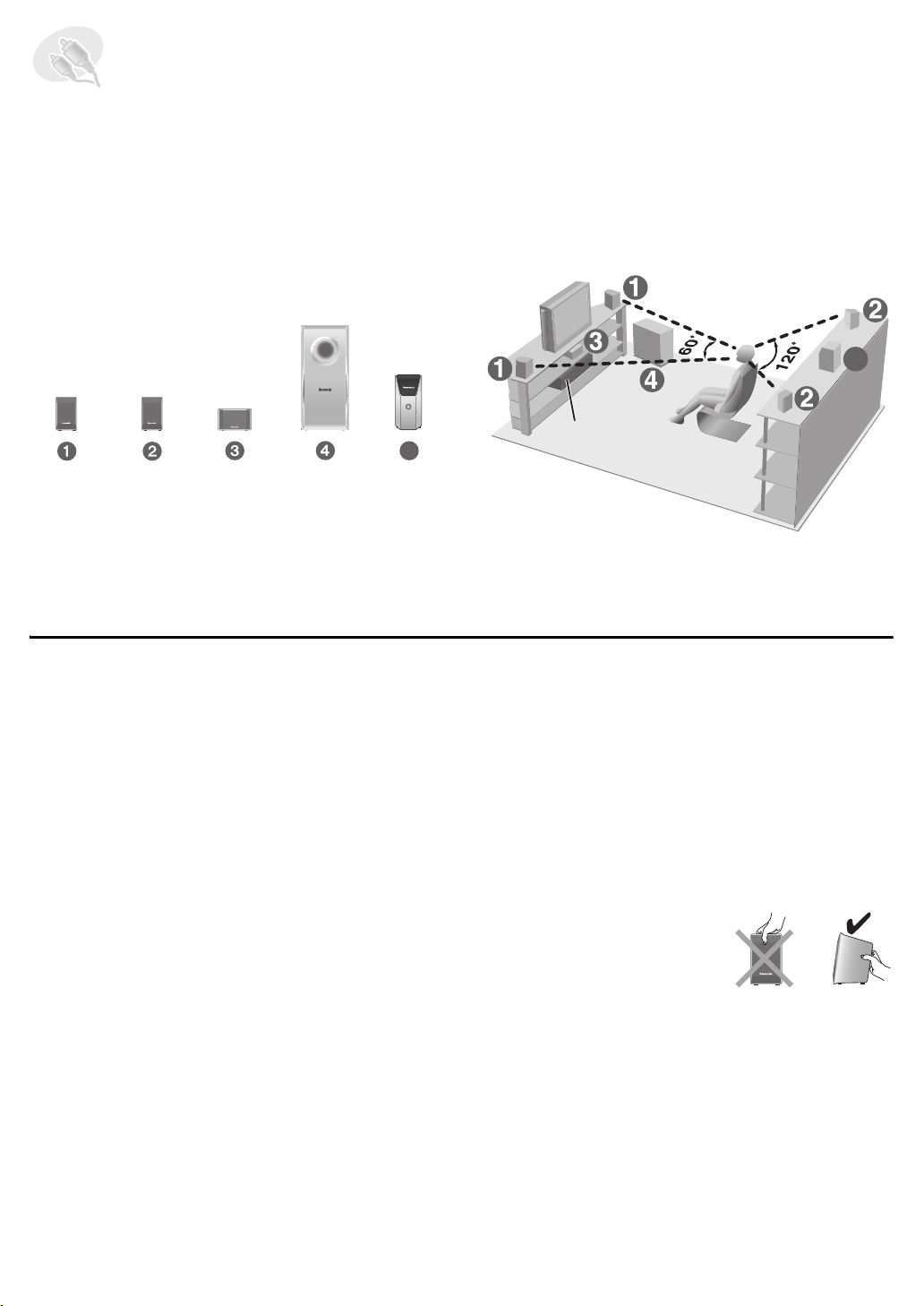
STEP1 Positioning the speakers
How you set up your speakers can affect the bass and the sound field. Note the following points:
≥ Place speakers on flat secure bases.
≥ Placing speakers too close to floors, walls, and corners can result in excessive bass. Cover walls and windows with thick
curtains.
≥ Left and right speakers are interchangeable, but front and surround speakers are not.
≥ Place the front, center, and surround speakers at approximately the same distance from the seating position.
The angles in the diagram are approximate.
Setup example
5
This unit
5
FRONT
(L, R)
SURROUND
(L, R)
CENTER
SUBWOOFER
WIRELESS
SYSTEM
Connect the supplied speakers and subwoofer to this unit only.
Do not attempt to connect the supplied speakers and subwoofer
to the external amplifier and so on.
(with digital transceiver)
≥ Use only supplied speakers
Using other speakers can damage the unit, and sound
quality will be negatively affected.
≥ Set the speakers up on an even surface to prevent them
from falling. Take proper precautions to prevent the
speakers from falling if you cannot set them up on an
even surface.
This unit
[Note]
≥ Keep your speakers at least 10 mm away from the
system for proper ventilation.
≥ To allow for proper ventilation and to maintain good
airflow around this unit, position it with at least 5 cm of
space on all sides.
≥ Do not block the ventilation holes of this unit.
Center speaker
≥ Vibration caused by the center speaker can disrupt the
picture if it is placed directly on the television. Put the
center speaker on a rack or shelf.
≥ To prevent the speakers from falling, do not place directly
on top of the television.
Wireless system
≥ Place the wireless system within approximately 10 m
from this unit.
≥ Do not use the wireless system or the digital transceiver
in a metal cabinet or bookshelf.
Subwoofer
Place to the right or left of the television, on the floor or a
sturdy shelf so that it will not cause vibration. Leave about
30 cm from the television.
Caution
Do not touch the netted area
of the speakers.
e.g. Front speaker
2
Page 3
Notes on speaker use
≥ You can damage your speakers and shorten their useful
life if you play sound at high levels over extended periods.
≥ Reduce the volume in the following cases to avoid
damage:
– When playing distorted sound.
– When the speakers are reverberating due to a record
player, noise from FM broadcasts, or continuous
If irregular coloring occurs on your television
The front and center speakers are designed to be used
close to a television, but the picture may be affected with
some televisions and setup combinations.
If this occurs, turn the television off for about 30 minutes.
The demagnetizing function of the television should correct
the problem. If it persists, move the speakers further away
from the television.
signals from an oscillator, test disc, or electronic
instrument.
– When adjusting the sound quality.
– When turning the unit on or off.
Caution
≥ This unit and the supplied speakers are to be used
only as indicated in this setup. Failure to do so may
lead to damage to the amplifier and/or the
speakers, and may result in the risk of fire. Consult
a qualified service person if damage has occurred
or if you experience a sudden change in
performance.
≥ Do not attempt to attach these speakers to walls
using methods other than those described in this
manual.
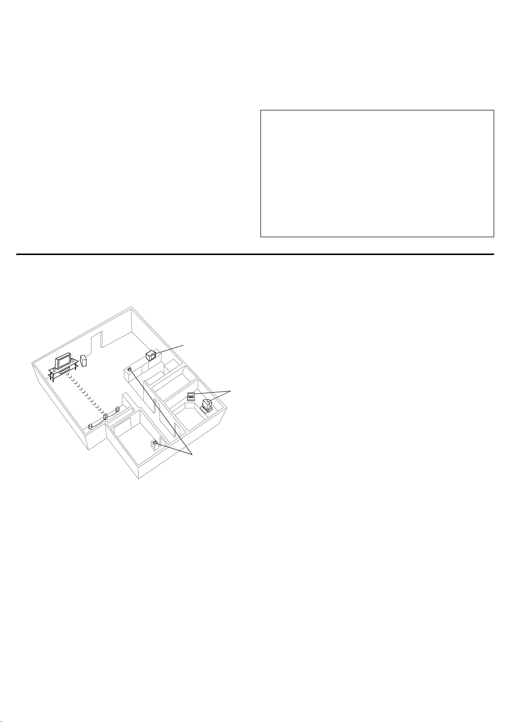
∫ Avoiding interference
To avoid possible interference, do not place the wireless system near any of the following devices.
The wireless system uses the same radio frequencies as other devices that may be present in your home.
e.g.
2.4GHz-band microwave oven
personal computer with 2.4GHz-band
wireless LAN
2.4GHz-band cordless phone
The wireless system will automatically seek a clear channel if any of these other devices interfere with its communication.
When this happens, the wireless link indicator (“ [W] ”) flashes on this unit, and there is a brief interruption in audio coming
from the surround speakers.
This is the normal operation of the product working to assure the best possible performance of your Home Theater System.
If the interference persists, try moving the other devices to another location outside the range of the wireless system.
3
Page 4
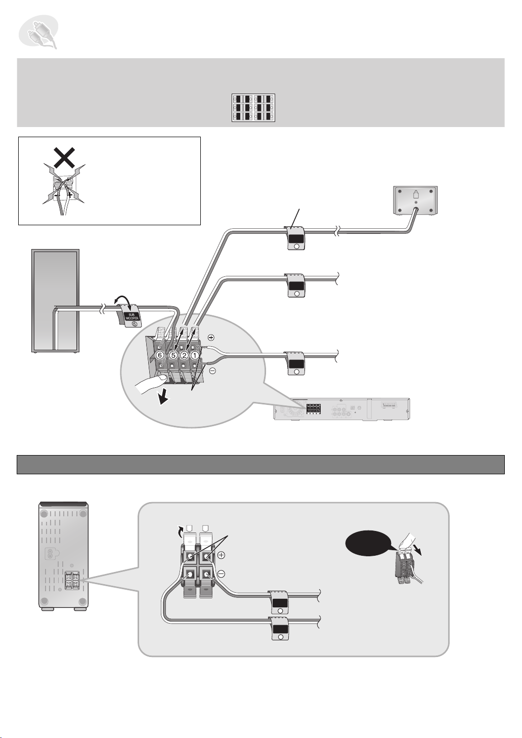
STEP2 Speaker connections
1 sheet of speaker cable stickers
≥ Attach the speaker-cable stickers to make connection easier.
Be careful not to cross
(short-circuit) or
reverse the polarity of
the speaker wires as
doing so may damage
the speakers.
CENTER
WOOFER
SUB
6
5
5
6
SUB
WOOFER
CENTER
SURROUND
SURROUND
Rch
Lch
3
4
4
3
Rch
SURROUND
SURROUND
FRONT
FRONT
Rch
Lch
2
1
1
2
Lch Lch
Rch
FRONT
FRONT
Speaker cable sticker
CENTER
5 CENTER
5
FRONT
Rch
2
6 SUBWOOFER
FRONT
Lch
1
Insert the wire fully.
Push!
i: White
j: Blue
Connecting the surround speaker cables to the wireless system
Wireless system
R
L
Insert the wire fully.
i: White
j: Blue
2 FRONT (R)
1 FRONT (L)
This unit
Click!
SURROUND
Rch
4
SURROUND
Lch
3
4 SURROUND (R)
3 SURROUND (L)
4
Page 5

STEP3 Digital transceiver connection
75
VIDEO
OUT
S-VID EO
OUT
AUX
Digital transceiver
This unit
Insert the digital transceiver
into the slot.
Do not insert or remove
FM ANT
COMPONENT VIDEO OUT
B
P
R
P
VIDEO
OUT
Y
Digital Transceiver
S-VIDEO
OUT
while this unit is on.
Digital transceiver
Insert fully until you hear a click.
STEP4 Audio, video and radio connections
≥ Do not connect through the video cassette recorder.
Due to copy guard protection, the picture may not be displayed properly.
≥ Turn the television off before connecting, and refer to the television’s operating instructions.
Connecting to a television with SCART (AV) terminal
To improve picture quality, you can change the video signal output from the SCART (AV) terminal.
Select “RGB/No Output” from QUICK SETUP (➜ page 11).
≥ This connection will also enable you to play audio from your television through your home theater system.
Refer to “Operating other equipment” (➜ page 39, Operations Guide).
Back of this unit
r
s
Scart cable (not included)
≥ To listen to the sound from the
television, select the appropriate
audio out (e.g., Monitor) on the
television.
Sound from the television
Press [EXT-IN] to select the “TV” audio input
on the remote control (➜ page 39,
Operations Guide).
COMPONENT VIDEO OUT
Y
P
B
P
R
VIDEO
S-VIDEO
OUT
OUT
Digital Transceiver
Television
L
R
AUX
AV
(not included)
5
Page 6

Connecting to a television with AUDIO/VIDEO terminals
S-VID EO
OUT
AUX
VIDEO
OUT
AUX
VIDEO
OUT
S-VID EO
OUT
Back of this unit
r
s
COMPONENT VIDEO OUT
L
R
AUX
Y
P
B
P
R
S-VIDEO
VIDEO
OUT
OUT
Digital Transceiver
AV
Tel evi sio n
(not included)
AUDI O
OUT
L
R
VIDEO OUT
AUDI O
IN
VIDEO IN
Audio cable
(not included)
§
Video cable
(not included)
§
This audio connection will enable you to play audio from your television through your home theater system.
Refer to “Operating other equipment” (➜ page 39, Operations Guide).
Using other video connections for improved picture quality
∫ Television with an S-VIDEO IN terminal
The S-VIDEO OUT terminal achieves a more vivid picture than the VIDEO OUT terminal by separating the chrominance
(C) and luminance (Y) signals. (Actual results depend on the television.)
Back of this unit
r
s
COMPONENT VIDEO OUT
L
R
AUX
Y
P
B
P
R
VIDEO
S-VIDEO
OUT
OUT
Digital Transceiver
AV
Tel evi sio n
(not included)
§
AUDI O
AUDI O
OUT
IN
L
R
VIDEO OUT
§
This audio connection will enable you to play audio from your television through your home theater system.
S-VIDEO
IN
S-video cable
(not included)
Audio cable
(not included)
Refer to “Operating other equipment” (➜ page 39, Operations Guide).
6
Page 7

∫ Television with COMPONENT VIDEO IN terminals
S-VID EO
OUT
AUX
VIDEO
OUT
COMPONENT VIDEO OUT
The COMPONENT VIDEO OUT terminals provides a purer
picture than the S-VIDEO OUT terminal. These terminals
can be used for either interlaced or progressive output.
Connection using these terminals outputs the colour
difference signals (PB/PR) and luminance signal (Y)
separately in order to achieve high fidelity in reproducing
colours.
Back of this unit
≥ The description of the component video input terminals
depends on the television or monitor
(e.g. Y/P
the same colour.
≥ When making this connection, select “Video/YPbPr”
(Video and YPbPr) or “S-Video/YPbPr” (S-Video and
YPbPr) from QUICK SETUP (➜ page 11). If “RGB/No
Output” (RGB only) is selected, the RGB signal is output
from the SCART (AV) terminal, but no signal is output
from the component video output terminals.
B/PR, Y/B-Y/R-Y, Y/CB/CR). Connect to terminals of
AV
Television
(not included)
AUDI O
VIDEO IN
OUT
L
R
S-VIDEO
IN
r
s
Audio cable
(not included)
COMPONENT
VIDEO IN
PB
PR
Y
COMPONENT VIDEO OUT
L
R
AUX
§
Y
P
B
P
R
S-VIDEO
VIDEO
OUT
OUT
Digital Transceiver
Video cables
(not included)
§
This audio connection will enable you to play audio from your television through your home theater system.
Refer to “Operating other equipment” (➜ page 39, Operations Guide).
To enjoy progressive video
≥ Connect to a progressive output compatible television.
≥ Set “Video Output Mode” to “480p” or “576p”, and then follow the instructions on the menu screen (➜ page 28,
Picture Menu, Operations Guide).
≥ Panasonic televisions with 625 (576)/50i·50p, 525 (480)/60i·60p input terminals are progressive compatible.
Consult the manufacturer if you have another brand of television.
7
Page 8

Connecting the FM and AM antennas
AM loop antenna FM indoor antenna
≥ Using an outdoor antenna (optional) (➜ page 35, Operations Guide).
FM indoor antenna
Click!
AM loop antenna
Stand the antenna up on its base.
Place the antenna where reception is best.
Keep loose antenna cable away from other
wires and cables.
Affix this end of the antenna where
reception is best.
Adhesive tape
This unit
While pushing, insert the wire fully.
White
Red
Black
Loosen the terminal screw with
a Phillips-head screwdriver.
Re-tighten the
terminal screw.
8
Page 9

STEP5 AC mains lead connections
2 AC mains leads
≥ Connect the AC mains leads after all other connections are complete.
This unit
AC mains lead
To household mains socket
(AC 230–240 V, 50 Hz)
To household mains socket
(AC 230–240 V, 50 Hz)
BE SURE TO READ THE CAUTION FOR THE
AC MAINS LEAD ON PAGE 4 IN THE
OPERATIONS GUIDE BEFORE CONNECTION.
Wireless system
AC IN~
AC mains lead
Conserving power
This unit and the wireless system consume a small amount of power when they are in standby mode (this unit: approx.
0.5 W, wireless system: approx. 4 W). To save power when they are not to be used for a long time, unplug them from the
household mains socket. You will need to reset some memory items after plugging in this unit.
[Note]
The included AC mains leads are for use with this unit and wireless system only. Do not use them with other equipment.
Also, do not use cords for other equipment with this unit or wireless system.
9
Page 10

STEP6 Preparing the remote control
G
Remote control Batteries
≥ mix old and new batteries.
≥ use different types at the same time.
≥ heat or expose to flame.
≥ take apart or short circuit.
Do not:
Insert so the poles (i and j) match those in the remote
2
control.
3
≥ attempt to recharge alkaline or manganese batteries.
≥ use batteries if the covering has been peeled off.
Mishandling of batteries can cause electrolyte leakage
which can severely damage the remote control.
Remove the batteries if the remote control is not going to be
used for a long period of time. Store in a cool, dark place.
≥ Do not use rechargeable
1
R6/LR6, AA
type batteries.
∫ Use
Aim at the remote control signal sensor (➜ page 17,
Operations Guide), avoiding obstacles, at a maximum
range of 7 m directly in front of the unit.
STEP7 Presetting the radio stations
Up to 15 stations can be set in each band, FM and AM.
Press [TUNER/BAND] to select “FM” or “AM”.
TUNER/BAND
Numbered
buttons
ENTER
1
Press [-TUNE MODE] to select “MANUAL”.
2
Each time you press the button: MANUAL()PRESET
Press [X TUNING W] to tune to the preferred
3
frequency.
≥ To start automatic tuning, press and hold
While listening to the broadcast
4
Press [ENTER].
While the frequency and “PGM” are flashing on the
5
display
Press the numbered buttons to select a channel.
≥To select a 2-digit number
[X TUNING W] until the frequency starts scrolling.
Tuning stops when a station is found.
e.g. Display
e.g. To select 12:
DISC SFC
D.MIX
MONO
TG
[S10] ➜ [1] ➜ [2]
SLP
Alternatively, press [X, W], and then press [ENTER].
TUNING
-TUNE MODE
Confirming the preset channels
Press [TUNER/BAND] to select “FM” or “AM”.
1
Press [-TUNE MODE] to select “PRESET”.
2
Each time you press the button: MANUAL()PRESET
Press the numbered buttons to select the channel.
3
≥ To select a 2-digit number
e.g. 12: [S10] ➜ [1] ➜ [2]
Alternatively, press [X, W].
e.g. Display
DISC SFC
C
10
MONO
D.MIX
SLP
TG
Page 11

STEP8 Performing QUICK SETUP
The QUICK SETUP screen assists you to make necessary settings.
To display the picture from this unit, turn on your television and change
connected to this unit (e.g. VIDEO 1, AV 1, etc.). To change your television’s video input mode, refer to its
operating instructions.
≥ This remote control can perform some basic television operations (➜ page 39, Operations Guide).
the television’s
video input mode which is
ENTER
SETUP
DVD
RETURN
1
2
3
Turn on the unit.
Select “DVD/CD”.
Press and hold to show
the QUICK SETUP screen.
Select
4
Follow the messages and
make the settings.
≥Menu Language
≥TV Type
≥TV Aspect
Register
5
ENTER
6
≥Video Out (AV/Component)
(For details ➜ below)
Press to finish QUICK
SETUP.
Press repeatedly to exit.
∫ Details of settings
Menu Language
Choose the language for the
on-screen messages.
TV Type
Select to suit the type of
television.
TV Aspect
Choose the setting to suit
your television and
preference.
Video Out (AV/Component)
Choose the video signal
format to be output from the
SCART (AV) and Component
terminal.
≥ Boxed items are the factory settings in the above diagram.
≥ English ≥ Français ≥ Deutsch ≥ Italiano
≥ Español ≥ Polski ≥ Svenska ≥ Nederlands
≥ Standard (Direct View TV) ≥ CRT Projector ≥ LCD TV/Projector
≥ Projection TV ≥ Plasma TV
≥ 4:3 : Regular aspect television
≥ 16:9: Widescreen television
≥ Video/YPbPr : Video and YPbPr ≥ S-Video/YPbPr: S-Video and YPbPr
≥ RGB/No Output: RGB only
To change these settings later
Select “QUICK SETUP” in the “Others” menu (➜ page 32,
Operations Guide).
11
Page 12

Matsushita Electric Industrial Co., Ltd.
Web Site: http://panasonic.net
p
RQT8737-2B
F0406NK2056
 Loading...