

Panasonic SC-HC37GN, SC-HC37GSX, SC-HC37PU, SC-HC37GS Service Manual
© Panasonic Corporation 2012. All rights reserved.
Unauthorized copying and distribution is a violation of
law.
PSG1203017CE
Compact Stereo System
Model No. SC-HC37GN
SC-HC37GS
SC-HC37GSX
SC-HC37PU
Product Color: (K)...Black Type (For GN/GS/GSX only)
(S)...Silver Type
(W)...White Type (For GS/GSX/PU only)
(R)...Red Type (For GN/GS/GSX only)
TABLE OF CONTENTS
PAGE PAGE
1 Safety Precautions----------------------------------------------- 3
1.1. General Guidelines---------------------------------------- 3
1.2. Caution for AC Cord (For GS/GSX)------------------- 4
1.3. Before Repair and Adjustment------------------------- 5
1.4. Protection Circuitry---------------------------------------- 5
1.5. Caution For Fuse Replacement------------------------ 5
1.6. Safety Part Information----------------------------------- 6
2 Warning-------------------------------------------------------------- 7
2.1. Prevention of Electro Static Discharge (ESD)
to Electrostatically Sensitive (ES) Devices---------- 7
2.2. Precaution of Laser Diode------------------------------- 8
2.3. Service caution based on Legal restrictions-------- 9
2.4. Handling Precaution for Traverse --------------------10
3 Service Navigation----------------------------------------------11
3.1. Service Information --------------------------------------11
4 Specifications ----------------------------------------------------12
5 General/Introduction -------------------------------------------13
5.1. Inserting or removing media---------------------------13
5.2. CD, iPod/iPhone & USB playback operations---- 14
6 Location of Controls and Component s------------------15
6.1. Main Unit & Remote Control Key Button
Operations------------------------------------------------- 15
7 Installation Instructions --------------------------------------16
7.1. Connections----------------------------------------------- 16
8 Service Mode-----------------------------------------------------17
8.1. Self Diagnostic Mode ----------------------------------- 17
8.2. Self Diagnostic Function Error Code----------------18
8.3. Doctor Mode Table---------------------------------------19
8.4. Sliding Door Operation --------------------------------- 25
9 Service Fixture & Tools---------------------------------------26
10 Disassembly and Assembly Instructions---------------27
10.1. Disassembly flow chart--------------------------------- 28
10.2. Types of Screws------------------------------------------29
10.3. Main Parts Location Diagram-------------------------29
10.4. Disassembly of Base Stand Assembly ------------- 30
10.5. Replacement of Door Assembly----------------------31

2
10.6. Replacement of Front Ornament Unit (L) & (R)--- 33
10.7. Disassembly of Front Panel Block-------------------34
10.8. Replacement of iPod Block----------------------------36
10.9. Disassembly of Interlock Switch P.C.B.-------------41
10.10. Disassembly of Remote Sensor P.C.B.-------------43
10.11 . Replacement of Gear Box Assembly ---------------46
10.12. Disassembly of Motor P.C.B.--------------------------48
10.13. Disassembly of Belt & Pulley Gear------------------49
10.14. Disassembly of Motor Assembly--------------------- 50
10.15. Disassembly of Centering Spring & Centering
Stopper------------------------------------------------------51
10.16. Disassembly of Lever Spring, Trigger Lever &
Driver Gear A ---------------------------------------------53
10.17. Disassembly of SW Lever, Relay Gear &
Driver Gear B ---------------------------------------------54
10.18. Disassembly of Shutter & Shutter Spring----------56
10.19. Disassembly of Upper Guide Rail & Top
Ornament---------------------------------------------------57
10.20. Disassembly of Bottom Ornament-------------------58
10.21. Disassembly of Lower Guide Rail--------------------59
10.22. Disassembly of SMPS P.C.B.-------------------------60
10.23. Replacement of Diode (D1700) ----------------------63
10.24. Disassembly of Panel P.C.B. & Button
Ornament Unit --------------------------------------------64
10.25. Disassembly of Button P.C.B.-------------------------65
10.26. Disassembly of Button Ornament--------------------66
10.27. Disassembly of CD Mechanism ----------------------67
10.28. Disassembly of CD Servo P.C.B.---------------------68
10.29. Disassembly of Jack Lid--------------------------------70
10.30. Disassembly of Main P.C.B.---------------------------71
10.31. Disassembly of Passive Radiator (SP3 &
SP4) ---------------------------------------------------------74
10.32. Disassembly of Front Speaker (SP1)---------------74
10.33. Disassembly of Front Speaker (SP2)---------------77
10.34. Disassembly of Passive Radiator (SP5) -----------79
10.35. Disassembly of Passive Radiator (SP6) -----------79
11 Service Position -------------------------------------------------80
11.1. Checking & Repairing of SMPS P.C.B.-------------80
11.2. Checking & Repairing of Panel P.C.B.-------------- 81
11.3. Checking & Repairing of CD Servo P.C.B.---------83
11.4. Checking & Repairing of Main P.C.B. (Side B) --- 86
11.5. Checking & Repairing of Main P.C.B. (Side A) --- 86
12 Block Diagram ---------------------------------------------------93
12.1. SERVO & SYSTEM CONTROL (1/2) BLOCK
DIAGRAM--------------------------------------------------93
12.2. SERVO & SYSTEM CONTROL (2/2) BLOCK
DIAGRAM--------------------------------------------------94
12.3. IC TERMINAL CHART----------------------------------95
12.4. AUDIO BLOCK DIAGRAM ----------------------------96
12.5. POWER SUPPLY (1/2) BLOCK DIAGRAM-------97
12.6. POWER SUPPLY (2/2) BLOCK DIAGRAM-------98
13 Wiring Connection Diagram---------------------------------99
14 Schematic Diagram------------------------------------------- 101
14.1. Schematic Diagram Notes--------------------------- 101
14.2. CD SERVO CIRCUIT (1/2) -------------------------- 103
14.3. CD SERVO CIRCUIT (2/2) -------------------------- 104
14.4. MAIN CIRCUIT (1/4) ---------------------------------- 105
14.5. MAIN CIRCUIT (2/4) ---------------------------------- 106
14.6. MAIN CIRCUIT (3/4) ---------------------------------- 107
14.7. MAIN CIRCUIT (4/4) ---------------------------------- 108
14.8. iPod & REMOTE SENSOR CIRCUIT-------------109
14.9. PANEL, INTERLOCK SWITCH, MOTOR &
BUTTON CIRCUIT-------------------------------------110
14.10. SMPS CIRCUIT-----------------------------------------111
15 Printed Circuit Board-----------------------------------------112
15.1. CD SERVO P.C.B.--------------------------------------112
15.2. MAIN P.C.B. (Side A)----------------------------------113
15.3. MAIN P.C.B. (Side B)----------------------------------114
15.4. iPod & REMOTE SENSOR P.C.B.----------------- 115
15.5. PANEL, INTERLOCK SWITCH & MOTOR
P.C.B.------------------------------------------------------116
15.6. BUTTON & SMPS P.C.B.-----------------------------117
16 Appendix Information of Schematic Diagram -------119
16.1. Voltage Measurement & Waveform Chart-------- 119
16.2. Illustration of IC’s, Transistors and Diodes-------125
16.3. Terminal Function of IC’s -----------------------------126
17 Exploded View and Replacement Parts List----------127
17.1. Exploded View and Mechanical replacement
Parts List--------------------------------------------------127
17.2. Electrical Replacement Parts List ------------------133
3
1 Safety Precautions
1.1. General Guidelines
1. When servicing, observe the original lead dress. If a short circuit is found, replace all parts which have been overheated or
damaged by the short circuit.
2. After servicing, see to it that all the protective devices such as insulation barriers, insulation papers shields are properly
installed.
3. After servicing, carry out the following leakage current checks to prevent the customer from being exposed to shock hazards.
1.1.1. Leakage Current Cold Check
1. Unplug the AC cord and connect a jumper between the two prongs on the plug.
2. measure the resistance value, with an ohmmeter between the jumpered AC plug and e ach exposed metallic cabinet part on
the equipment such as screwheads, connectors, control shafts, etc. When the exposed metallic part has a return path to the
chassis, the reading should be between 1MΩ and 5.2MΩ. When the exposed metal does no t have a return path to the chas-
sis, the reading must be
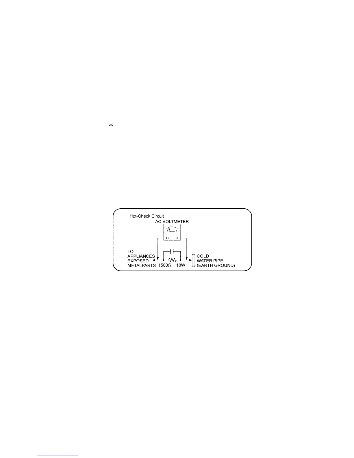
1.1.2. Leakage Current Hot Check
1. Plug the AC cord directly into the AC outlet. Do not use an isolation transformer for this check.
2. Connect a 1.5kΩ, 10 watts resistor, in parallel with a 0.15μF capacitors, between each exposed metallic part on the set and a
good earth ground such as a water pipe, as shown in Figure 1.
3. Use an AC voltmeter, with 1000 ohms/volt or more sensitivity, to measure the potential across the resistor.
4. Check each exposed metallic part, and measure the voltage at each point.
5. Reverse the AC plug in the AC outlet and repeat each of the above measurements.
6. The potential at any point should not exceed 0.75 volts RMS. A leakage current tester (Simpson Model 229 or equiva lent)
may be used to make the hot checks, leakage current must not exceed 1/2 milliamp. In case a measurement is outside of the
limits specified, there is a possibility of a shock hazard, and the equipment should be repaired and rechecked before it is
returned to the customer.
Figure. 1
4
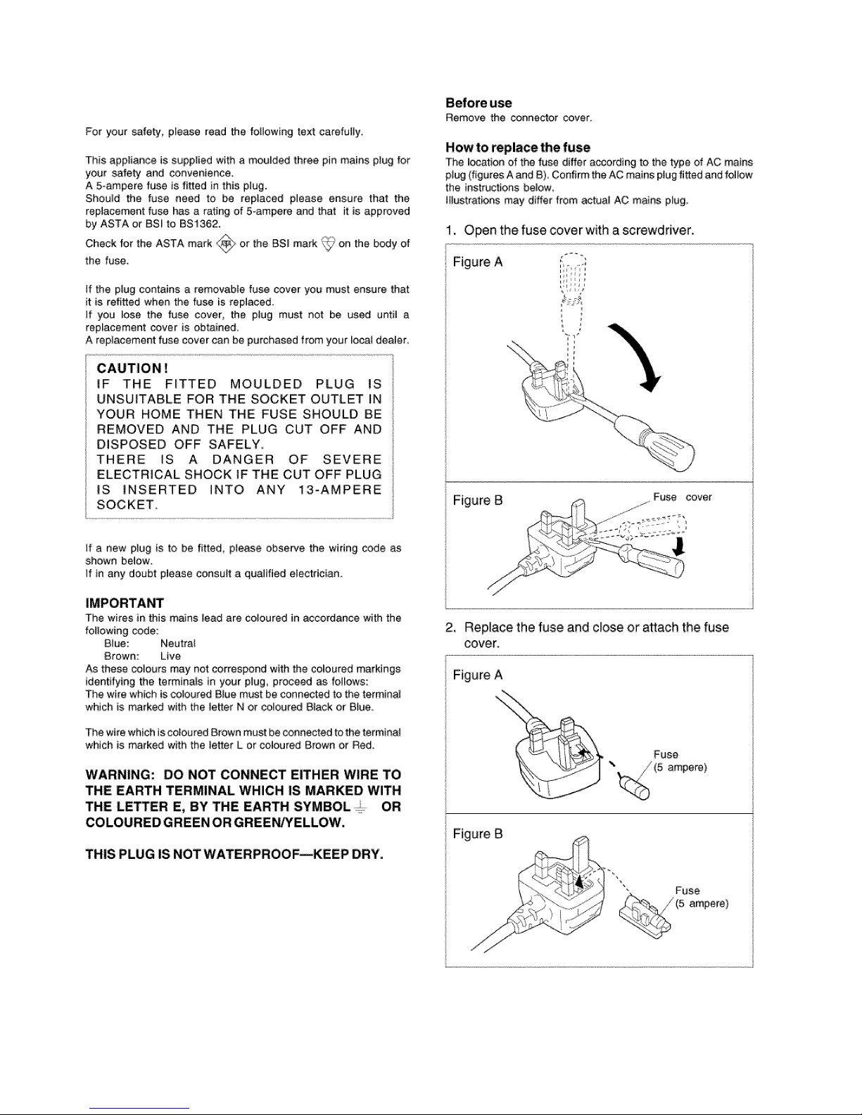
1.2. Caution for AC Cord (For GS/GSX)
5
1.3. Before Repair and Adjustment
Disconnect AC power, discharge unit AC Capacitors as such C1702, C1710, C1725, C1727, and C1728 through a 10W, 1W resistor to ground.
Caution : DO NOT SHORT-CIRCUIT DIRECTLY (with a screwdriver blade, for instance), as this may destroy solid state devices.
After repairs are completed, restore power gradually using a variac, to avoid overcurrent.
• Current consumption at AC 110V to 240V, at 50/60Hz in NO SIGNAL mode (at volume min in FM Tuner mode) should be ~200
mA. (For GS/GSX/PU)
• Current consumption at AC 220V to 240V, at 50Hz in NO SIGNAL mode (at volume min in FM Tuner mode) should be ~200 mA.
(For GN)
1.4. Protection Circuitry
The protection circuitry may have operated if either of the following conditions are noticed:
• No sound is heard when the power is turned on.
• Sound stops during a performance.
The function of this circuitry is to prevent circuitry damage if, for example, the positive and n egative speaker connection wires are
"shorted", or if speaker systems with an impedance less than the indicated rated impedance of the amplifier are used.
If this occurs, follow the procedure outlines below:
1. Turn off the power.
2. Determine the cause of the problem and correct it.
3. Turn on the power once again after one minute.
Note:
When the protection circuitry functions, the unit will not operate unless the power is first turned off and then on again.
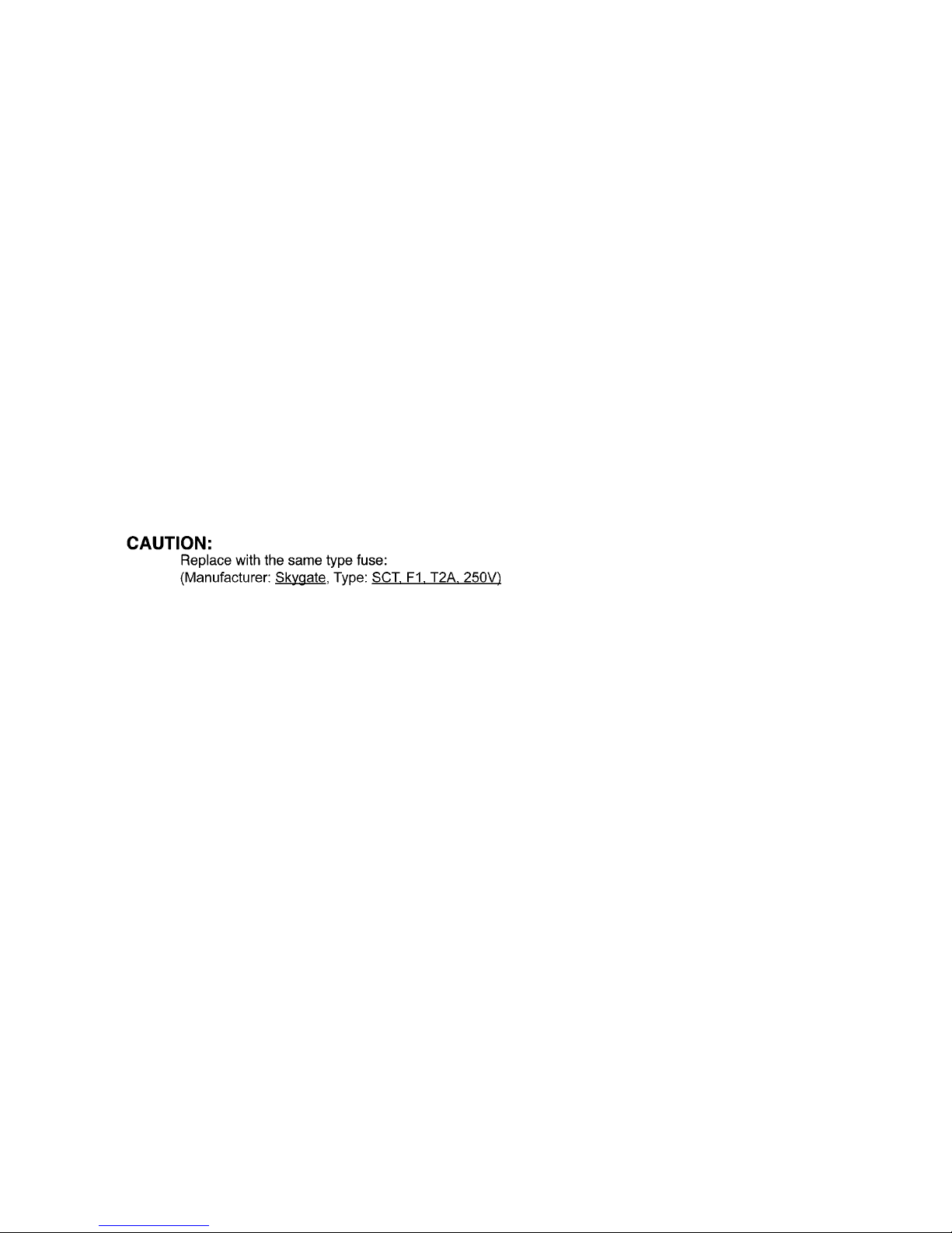
1.5. Caution For Fuse Replacement

6
1.6. Safety Part Information
Safety Parts List:
There are special components used in this equipment which are important for safety.
These parts are marked by in the Schematic Diagrams, Exploded View & Replacement Pa rts List. It is essential that these
critical parts should be replaced with manufacturer’s specified parts to prevent shock, fire or other hazards. Do not modify the
original design without permission of manufacturer.
Safety Ref. No. Part No. Part Name & Description Remarks
27 RFKHHC37PU-S REAR CABINET ASS’Y PU-S
27 RFKHHC37PU-W REAR CABINET ASS’Y PU-W
27 RFKHHC37GS-W REAR CABINET ASS’Y GS-W GSX-W
27 RFKHHC37GS-S REAR CABINET ASS’Y GS-S GS-K, GS-R, GSX-S, GSX-K, GSX-R
27 RFKHHC37GN-S REAR CABINET ASS’Y GN-S, GN-R, GN-K
59 RMV0390 SMPS INSULATOR A
60 RMV0391-1 SMPS INSULATOR B
62 RSC1072 SMPS SHIELD PLATE
63 RSC1073-1 SMPS BRACKET
301 RAE5301Z-V TRAVERSE UNIT
A1 N2QAYC000057 REMOTE CONTROL
A2 K2CQ2CA00007 AC CORD GS PU GSX
A2 K2CJ2DA00008 AC CORD GN
A2 K2CZ3YY00024 AC CORD (3 PIN) GS,GSX
A2 K2CP2YY00061 AC CORD GS,GSX
A2 K2CA2YY00039 AC CORD PU
A3 RQT9644-1M O/I BOOK (Sp/Pr) PU
A3 RQT9640-1L O/I BOOK (En) GN
A3 RQT9641-G O/I BOOK (Ar) GS,GSX
C1702 F0CAF224A105 0.22uF
C1710 F1BAF471A013 470pF
C1725 F0CAF154A105 0.15uF
C1727 F1BAF1020020 1000pF
C1728 F1BAF1020020 1000pF
F1 K5G202Y00006 FUSE
L1702 G0B183E00004 LINE FILTER
L7001 EXC24CE900U NOISE FILTER
P1751 K2AA2B000011 AC INLET
PC1701 B3PBA0000503 PHOTO COUPLER
PCB9 REP4774C SMPS P.C.B. (RTL)
R1724 E RJ12YJ155U 1.5M 1/2W
R1726 E RJ12YJ155U 1.5M 1/2W
T1100 G4D1A0000117 SWITCHING TRANSFORMER
T1700 G4DYZ0000059 MAIN TRANSFORMER
TH1701 D4CAA5R10001 THERMISTOR
Z1752 ERZV10V511CS ZNR

7
2Warning
2.1. Prevention of Electro Static Discharge (ESD) to Electrostatically Sensi-
tive (ES) Devices
Some semiconductor (solid state) devices can be damaged easily by static electricity. Such components commonly are called Electrostatically Sensitive (ES) Devices. Examples of typical ES devices are integrated circuits and some field-effect transistors and
semiconductor “chip” components. The following techniques should be used to help reduce the incidence of component damage
caused by electrostatic discharge (ESD).
1. Immediately before handling any semiconductor component or semiconductor-equiped assembly, drain off any ESD on your
body by touching a known earth ground. Alternatively, obtain and wear a commercially available discharging ESD wrist strap,
which should be removed for potential shock reasons prior to applying power to the unit under test.
2. After removing an electrical assembly equiped with ES devices, place the a ssemb ly on a co nductive surfa ce such as alu min-
ium foil, to prevent electrostatic charge build up or exposure of the assembly.
3. Use only a grounded-tip soldering iron to solder or unsolder ES devices.
4. Use only an anti-static solder remover device. Some solder removal devices not classified as “anti-static (ESD protected)” can
generate electrical charge sufficient to damage ES devices.
5. Do not use freon-propelled chemicals. These can generate electrical charges sufficient to damage ES devices.
6. Do not remove a replacement ES device from its protective package until immediately before you are ready to install it. (Most
replacement ES devices are packaged with leads electrically shorted together by conductive foam, aluminium foil or comparable conductive material).
7. Immediately before removing the protective material from the leads of a replacement ES device, touch the protective material
to the chassis or circuit assembly into which the device will be installed.
Caution :
Be sure no power is applied to the chassis or circuit, and observe all other safety precautions.
8. Minimize bodily motions when handling unpackaged replacement ES devices. (Otherwise harmless motion such as the
brushing together of your clothes fabric or the lifting of your foot from a carpeted floor can generate static electricity (ESD) sufficient to damage an ES device).
8
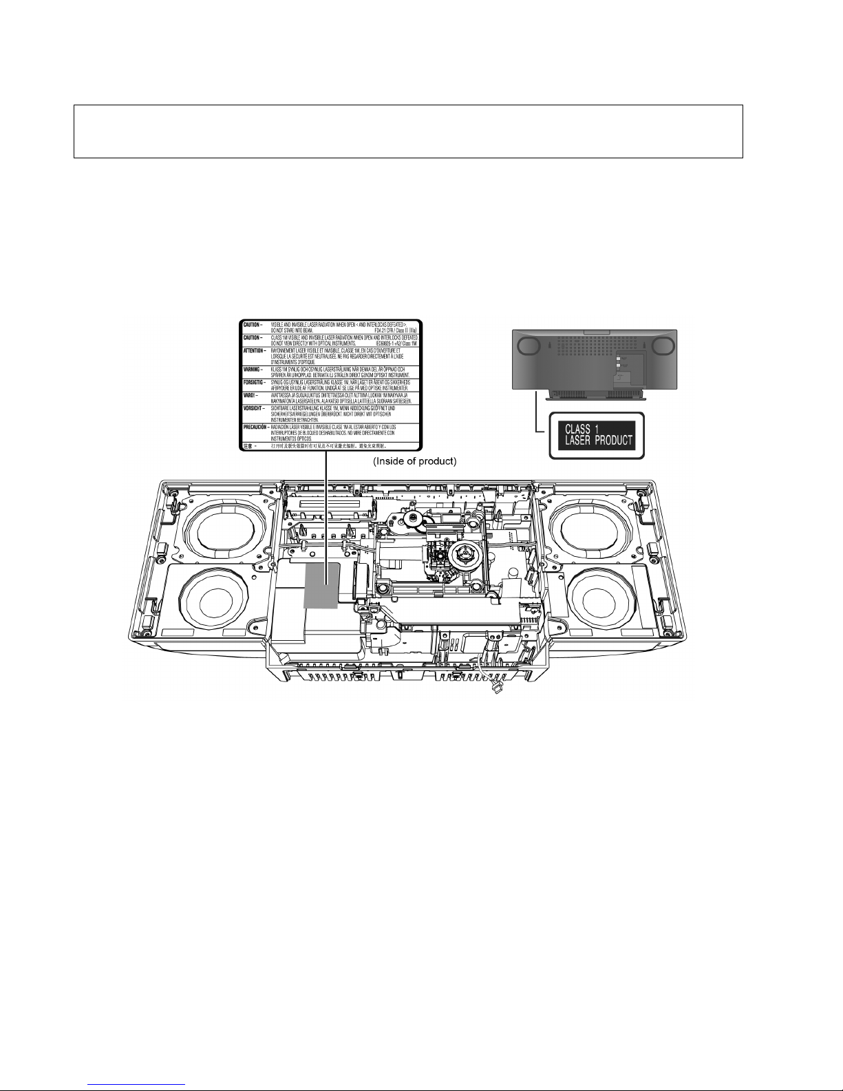
2.2. Precaution of Laser Diode
Caution:
This product utilizes a laser diode with the unit turned "on", invisible laser radiation is emitted from the pickup lens.
Wavelength: 790 nm (CD)
Maximum output radiation power from pick up: 100 μW/VDE
Laser radiation from the pickup unit is safety level, but be sure the followings:
1. Do not disassemble the pickup unit, since radiation from exposed laser diode is dangerous.
2. Do not adjust the variable resistor on the pickup unit. It was already adjusted.
3. Do not look at the focus lens using optical instruments.
4. Recommend not to look at pickup lens for a long time.
CAUTION!
THIS PRODUCT UTILIZES A LASER.
USE OF CONTROLS OR ADJUSTMENTS OR PERFORMANCE OF PROCEDURES OTHER THAN THOSE SPECIFIED HEREIN MAY RESUL T
IN HAZARDOUS RADIATION EXPOSURE.
9
2.3. Service caution based on Legal restrictions
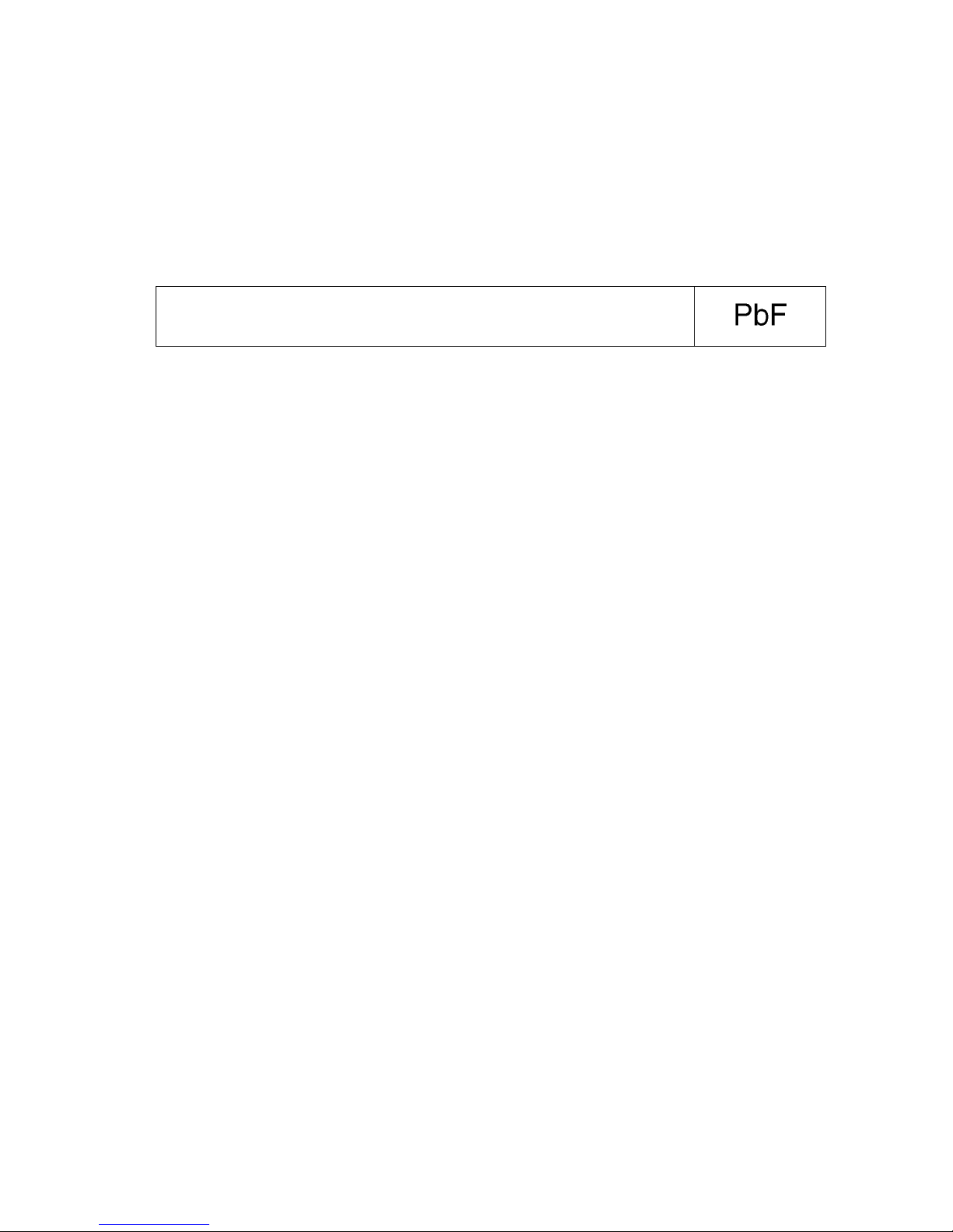
2.3.1. General description about Lead Free Solder (PbF)
The lead free solder has been used in the mounting process of all ele ctrical components on the printed circuit boards used for this
equipment in considering the globally environmental conservation.
The normal solder is the alloy of tin (Sn) and lead (Pb). On the other hand, the lead free solder is the alloy mainly consists of tin
(Sn), silver (Ag) and Copper (Cu), and the melting point of the lead free solder is higher approx.30 degrees C (86°F) more than that
of the normal solder.
Definition of PCB Lead Free Solder being used
Service caution for repair work using Lead Free Solder (PbF)
• The lead free solder has to be used when repairing the equipment for which the lead free solder is used.
(Definition: The letter of “PbF” is printed on the PCB using the lead free solder.)
• To put lead free solder, it should be well molten and mixed with the original lead free solder.
• Remove the remaining lead free solder on the PCB cleanly for soldering of the new IC.
• Since the melting point of the lead free solder is higher than that of the normal lead solder, it takes the longer time to melt the
lead free solder.
• Use the soldering iron (more than 70W) equipped with the temperature control after setting th e temperature a t 350±30 deg rees
C (662±86°F).
Recommended Lead Free Solder (Service Parts Route.)
• The following 3 types of lead free solder are available through the service parts route.
RFKZ03D01K-----------(0.3mm 100g Reel)
RFKZ06D01K-----------(0.6mm 100g Reel)
RFKZ10D01K-----------(1.0mm 100g Reel)
Note
* Ingredient: Tin (Sn), 96.5%, Silver (Ag) 3.0%, Copper (Cu) 0.5%, Cobalt (Co) / Germanium (Ge) 0.1 to 0.3%
The letter of “PbF” is printed either foil side or components side on the PCB using the lead free solder.
(See right figure)
10
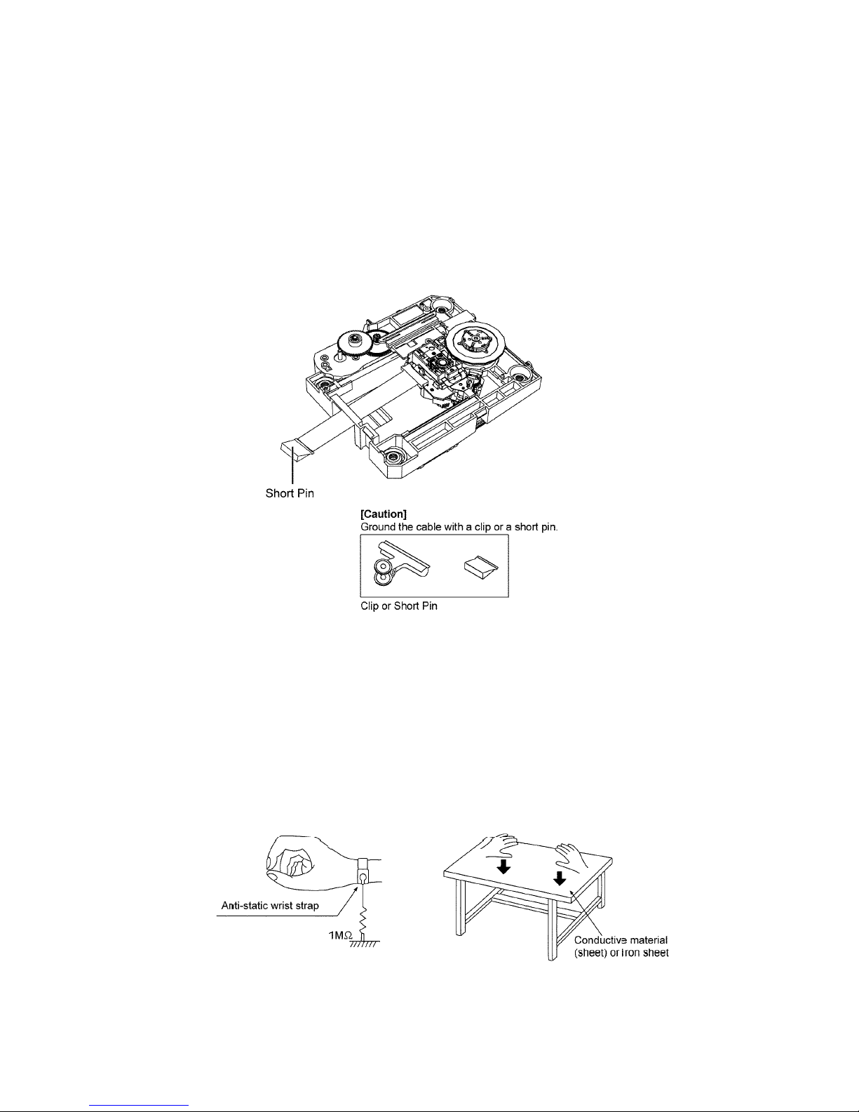
2.4. Handling Precaution for Traverse
The laser diode in the optical pickup unit may break down due to static electricity of clothes or human body. Special care must be
taken avoid caution to electrostatic breakdown when servicing and handling the laser diode in the Traverse.
2.4.1. Cautions to Be Taken in Handling the Optical Pickup Unit
The laser diode in the optical pickup unit may be damaged due to electrostatic discharge gene rating from clothes or human body.
Special care must be taken avoid caution to electrostatic discharge damage when servicing the laser diode.
1. Do not give a considerable shock to the optical pickup unit as it has an extremely high-precise structure.
2. To prevent the laser diode from the electrostatic discharge damage, the flexible cable of the optical pickup unit removed
should be short-circuited with a short pin or a clip.
3. The flexible cable may be cut off if an excessive force is applied to it. Use caution when handling the flexible cable.
4. The antistatic FPC is connected to the new optical pickup unit. After replacing the optical pickup unit and connecting the flexible cable, cut off the antistatic FPC.
2.4.2. Grounding for electrostatic breakdown prevention
Some devices such as the CD player use the optical pickup (laser diode) and the optical pickup will be damaged by static electricity
in the working environment. Proceed servicing works under the working environment where grounding works is completed.
2.4.2.1. Worktable grounding
1. Put a conductive material (sheet) or iron sheet on the area where the optical pickup is placed, and ground the sheet.
2.4.2.2. Human body grounding
1. Use the anti-static wrist strap to discharge the static electricity form your body (Figure 2).

11
3 Service Navigation
3.1. Service Information
This service manual contains technical information which will allow service personnel’s to understand and service this model.
Please place orders using the parts list and not the drawing reference numbers.
If the circuit is changed or modified, this information will b e fol lowed by supplemen t service manual to be filed with o riginal se rvice
manual.
• Micro-processor:
1) The following components are supplied as an assembled part.
- Micro-processor IC, (IC6002) (RFKWMHC37EG)

12
4 Specifications
Q General
Power consumption 25 W
Power consumption in standby
mode
Approx. 0.2 W
Power supply AC 110 V to 240 V, 50/60 Hz
(GN only) AC 220 V to 240 V, 50 Hz
Dimensions (W x H x D) 480 mm x 197 mm x 84 mm
Depth without stand 75 mm
Mass Approx. 2.5 kg
Operating temperature range 0 °C to +40 °C
Operating humidity range 35% to 80 % RH
(no condensation)
Q Amplifier Section
Output Power
RMS Output Power Stereo Mode
Front Ch (both ch driven) 20 W per channel (6 Ω),
1 kHz, 10% THD
Total RMS Stereo mode power 40 W
PMPO output power (GS only) 450 W
Q Tuner section
Preset Memory FM 30 stations
AM 15 stations
Frequency modulation (FM)
Frequency range 87.50 MHz to 108.00 MHz
(50 kHz step)
Antenna terminals 75 Ω (unbalanced)
Amplitude Modulation (AM)
Frequency range 522 kHz to 1629 kHz (9 kHz step)
520 kHz to 1630 kHz
(10 kHz step)
Q Terminals section
USB port
USB standard USB 2.0 full speed
Media file format support MP3 (*.mp3)
USB device file system FAT12, FAT16, FAT32
USB port power DC OUT 5 V, 500 mA MAX
iPod Connector DC OUT 5 V, 1.0 A MAX
Phone jack
Terminal Stereo, Ø3.5 mm jack
Q Disc Section
Disc played [8 cm or 12 cm]
CD, CD-R/RW (CD-DA, MP3*)
* MPEG-1 Layer 3, MPEG-2 Layer 3
Pick up
Wavelength 790 nm (CD)
Laser power CLASS 1
Audio output (Disc)
Number of channels 2 ch (FL, FR)
Q Speaker System Section
Type 1 way, 1 speaker system
(Passive Radiator)
Speaker unit(s)
Full range 6.5 cm Cone type x 1 per channel
Passive Radiator 8 cm x 2 per channel
Impedance 6 Ω
• Specifications are subject to change without notice. Mass and
dimensions are approximate.
• Total harmonic distortion is measured by the digital spectrum analyzer.
13
5 General/Introduction
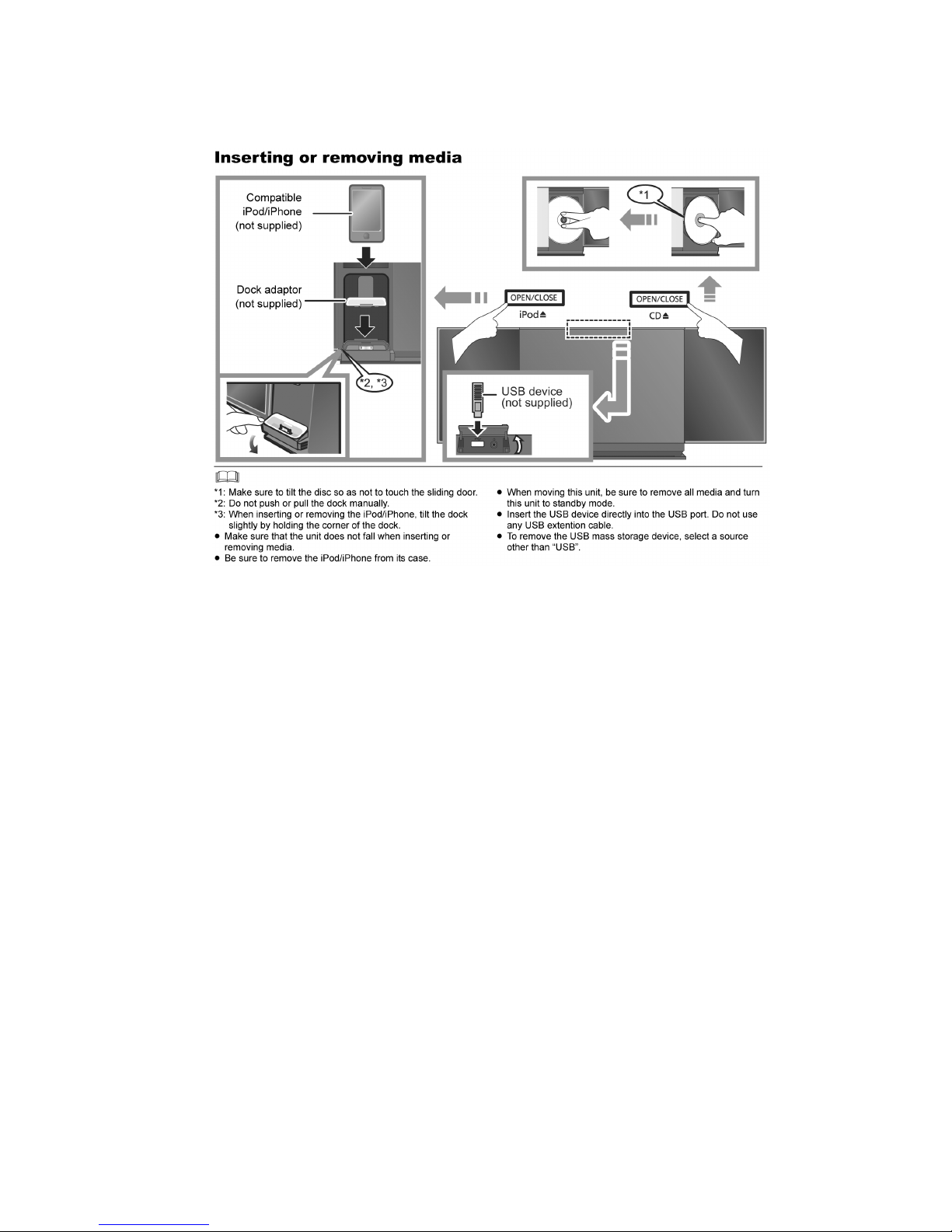
5.1. Inserting or removing media
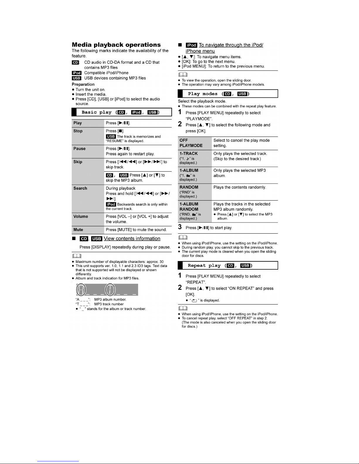
14
5.2. CD, iPod/iPhone & USB playback operations
Compatibility CD, iPod/iPhone & USB
• For compatibility of CD, iPod/iPhone & USB please refer to Operating Instructions.
15
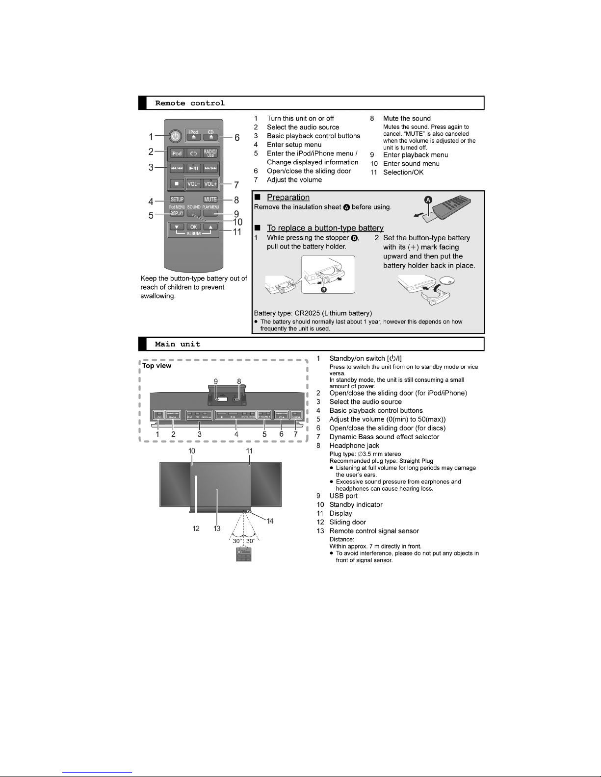
6 Location of Controls and Components
6.1. Main Unit & Remote Control Key Button Operations
16
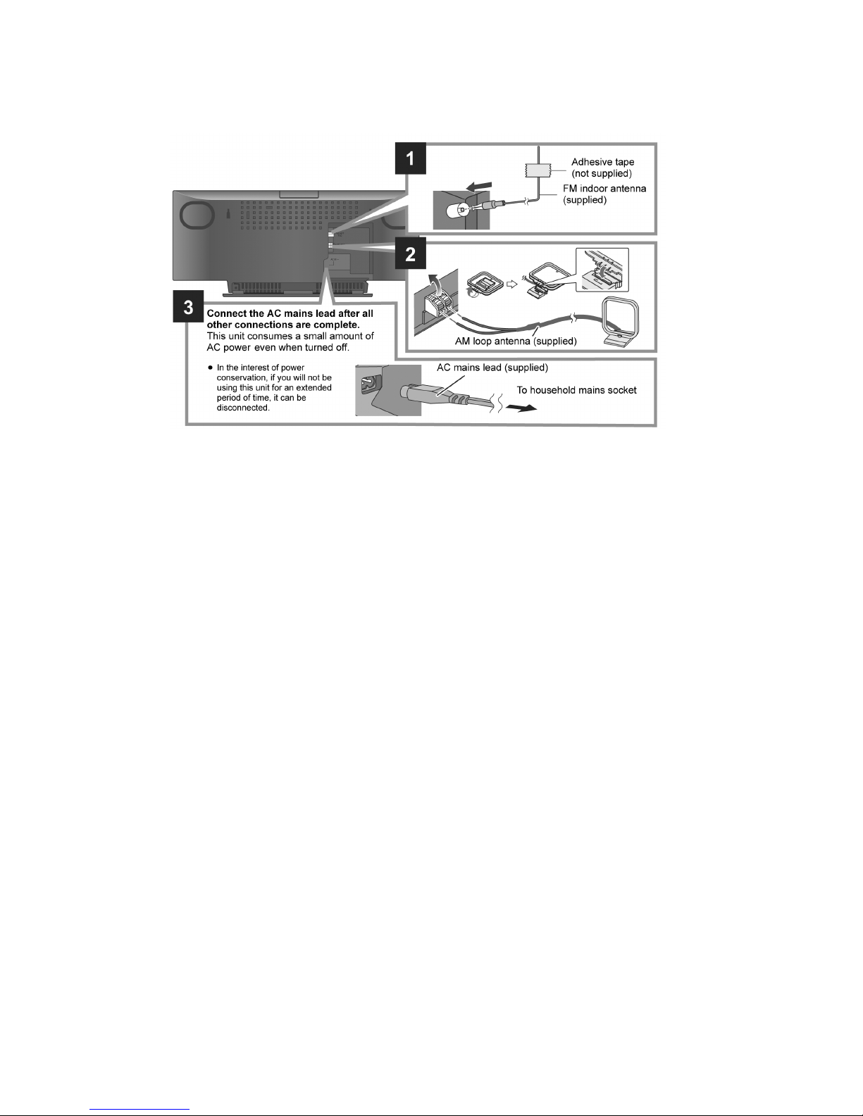
7 Installation Instructions
7.1. Connections
17
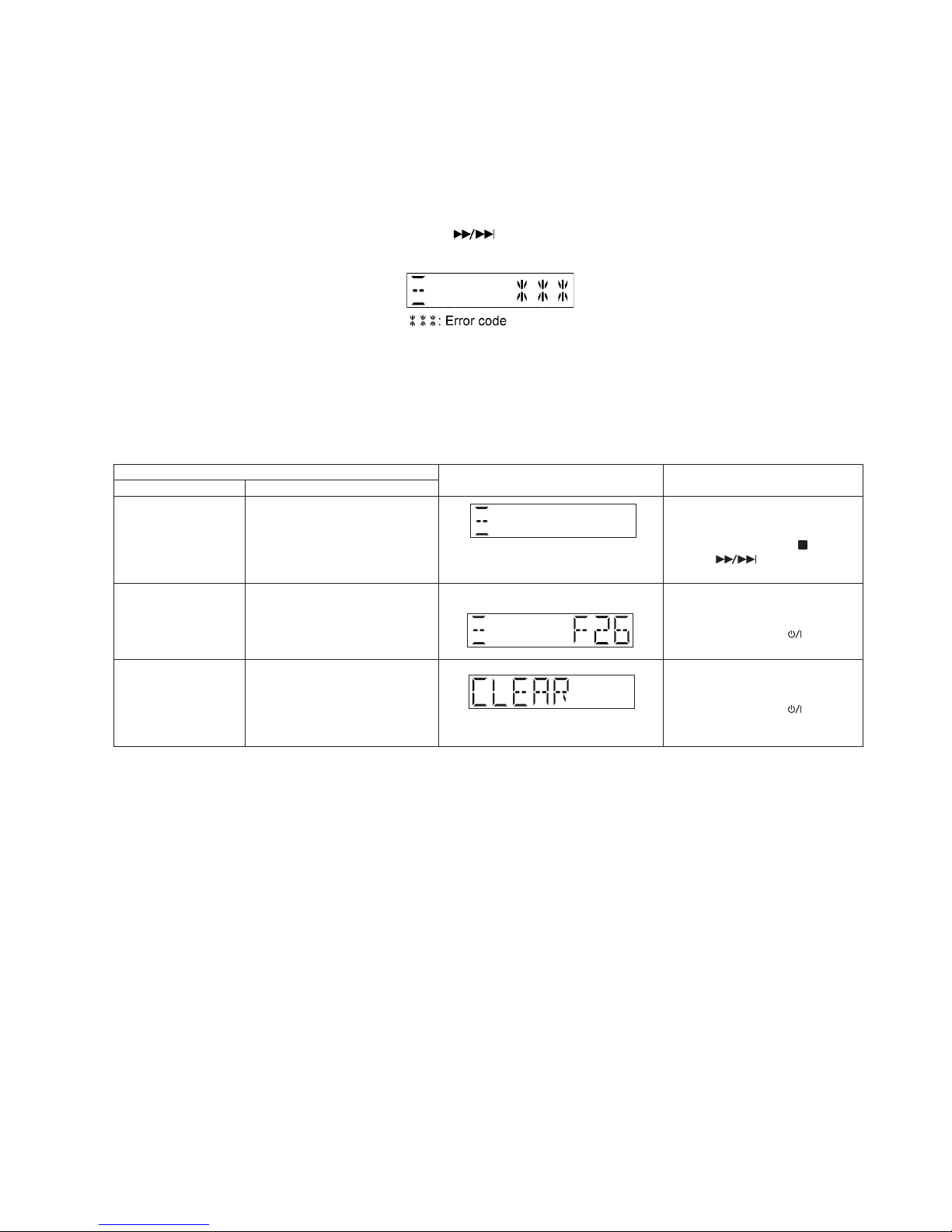
8 Service Mode
This unit is equipped with features of self diagnostic & doctor mode setting for checking the functions & reliability.
8.1. Self Diagnostic Mode
Here is the procedures to enter into Self Diagnostic Mode.
Step 1 : Turn on the unit.
Step 2 : Select CD mode.
Step 3 : Press and hold [Q] button for 2 seconds follow by [ ] on the unit.
Step 4 : The display show as follow.
To exit the Self Diagnostic Mode
Use either one of the following methods to cancel the Self Diagnostic Mode.
• Press the power button on the main unit or using the remote control.
• Unplug the AC cord.
8.1.1. Self Diagnostic Table
Self Diagnostic Mode To enter into self diagnostic
checking
Item
FL display Key operation
Mode name Description
Error code information
Delete Error code
Example:
System will perform a check on
any unusual/error code from the
memory
To clear the stored in memory
(EEPROM IC)
Step 1 : Select CD mode
(Ensure no disc is inserted).
Step 2 : Press and hold [ ] follow by
[ ] on main unit for 2
second .
Step 1 : In self diagnostic mode,
Press [STOP] on main unit.
To exit, press [TA] on main
unit or remote control.
Step 1 : In self diagnostic mode,
Press [0] on remote control.
To exit, press [TA] on main
unit or remote control.
18
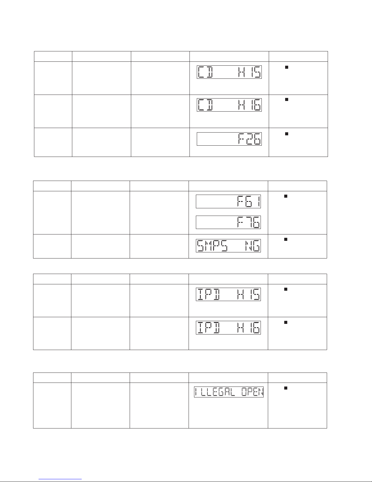
8.2. Self Diagnostic Function Error Code
8.2.1. CD Mechanism Error Code Table
8.2.2. Power Amp Error Code Table
8.2.3. iPod Error Code Table
8.2.4. Sliding Door Operation Error Code Table
of error Automatic FL Display Remarks
CD H15 CD Open Abnormal During operation
POS_SW_R On fail to be
detected within 4 sec. Error
No. shall be clear by force
or during cold start.
Press [
] on main unit for
next error.
CD H16 CD Closing Abnormal During operation
POS_SW_CEN On fail to
be detected within 4 sec.
Error No. shall be clear by
force or during cold start.
Press [
] on main unit for
next error.
F26 Communication between
CD servo LSI and micro-p
abnormal.
During switch to CD function, if SENSE = “L” within
failsafe time of 20ms.
Press [
] on main unit for
next error.
Error Code Diagnostic Contents Description of error
of error Automatic FL Display Remarks
F61/F76 Power Amp IC output
SMPS NG Checking SMPS Type
abnormal
During power-on, PDET1,
SMPS type and REGION
not match.
The unit will shutdown.
PDET2 & MAINV_DET /
TEMP_DET is “L” after 1
sec.
Press [
] on main unit for
next error.
Press [
] on main unit for
next error.
Error Code Diagnostic Contents Description of error
of error Automatic FL Display Remarks
IPD H15 iPod Open Abnormal During operation
POS_SW_L On fail to be
detected within 3 sec. Error
No. shall be clear by force
or during cold start.
Press [
] on main unit for
next error.
IPD H16 iPod Closing Abnormal During operation
POS_SW_CEN On fail to
be detected within 3 sec.
Error No. shall be clear by
force or during cold start.
Press [
] on main unit for
next error.
Error Code Diagnostic Contents Description of error
of error Automatic FL Display Remarks
ILLEGAL OPEN Sliding Door Open/Close
Abnormal
Refer to 8.4 for more
information
During Operation
1. Motor set to FREE RUN
condition after 2 retry fail to
detect any POS_SW.
2. Sliding Door Stop from
neutral to iPod open and
position sensor could not be
detected.
Press [
] on main unit for
next error.
Error Code Diagnostic Contents Description of error

19
8.3. Doctor Mode Table
Note : To enter the Doctor Mode, please use HC35 remote control.
Here is the procedures to enter into Doctor Mode.
Step 1 : Turn on the unit.
Step 2 : Select CD mode.
Step 3 : Pressing and hold [Q] on main unit then press [4] follow by [7] using the remote control.
Step 4 : The display show as follow.
To exit the Doctor mode
Use either one of the following methods to cancel the Doctor mode.
• Press the power button of the unit or using the remote control.
• Unplug the AC cord.
8.3.1. Doctor Mode Table 1
Item
FL Display
Key Operation
Mode Name Description Front Key
Doctor Mode To enter into Doctor Mode
for checking of various
items and displaying
EEPROM and firmware version.
Note: The micro-processor
version asshown is an
example. It will be revise
when there is an updates.
FL Displaysequence Dis-
play 1
2
(Display 1)
Checksum : (Condition 1)
(Display 2)
The Checksum of EEPROM and firmware
version will be display for 2 sec.
In any mode:
Press
[ ]
button on main unit follow by
[4] & then [7] on the remote control of
HC35.
To exit Doctor Mode, press
[TA]
button
on main unit or on the remote control of
HC35.
Version Display
(DEC)
Check sum
(HEX)
No Rom correction
20
8.3.2. Doctor Mode Table 2
Item
FL Display
Key Operation
Mode Name Description
Front Key
FL Display Te st To check the FL segments
display (All segments will
light up)
In Doctor Mode:
Press [1] button on the remote control of
HC35.
To cancel, press [0] button on remote
control. It returns Doctor Mode.
To cancel, press [0] button on remote
control. It returns Doctor Mode.
To cancel, press [0] button on remote
control. It returns Doctor Mode.
To cancel, press [0] button on remote
control. It returns Doctor Mode.
To exit Doctor Mode, press button on main unit or on the remote control
of HC35.
Vol ume Setting In Doctor Mode:
Press [7] button on the remote control of
HC35.
In Doctor Mode:
Press [8] button on the remote control of
HC35.
In Doctor Mode:
Press [9] button on the remote
control of
HC35.
Mecha Sliding Panel
Reliability
In Doctor Mode:
Press [ ] follow by [2] & then [1]
button on the remote control of HC35.
To cancel, press [0] button on remote
control. It returns Doctor Mode.
To exit Doctor Mode, press button on main unit or on the remote control
of HC35.
To exit Doctor Mode, press button on main unit or on the remote control
of HC35.
To exit Doctor Mode, press button on main unit or on the remote control
of HC35.
To exit Doctor Mode, press button on main unit or on the remote control
of HC35.
To check the operation of
sliding Panel.
Sequence as follow :
1. CD Door set to CLOSE
position.
2. CD Door move to the left
(CD Open direction) and
stop at LEFT position for 1
sec.
3. CD Door move to the
right (CD Close direction)
and stop at CLOSE position
for 1 sec.
4. All the process above is
considered as 1 cycle. Step
(2) ~ (3) will repeat; Cycle
Counter display increase
every 1 cycle completed.
Refer to 8.3.5 for more
information
To check for preset volume
setting
Note : In tuner mode this
function is not possible
21
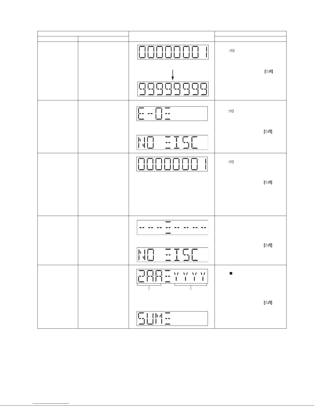
8.3.3. Doctor Mode Table 3
Item FL Display Key Operation
Mode Name Description Front Key
Cold Start
The [NO DISC] display will appear after 2s,
To display result of self
adjustment for CD.
The [NO DISC] display will appear after 3s,
In Doctor Mode:
Press [ ] follow by [1] & then [4]
button on the remote control of HC35.
To cancel, press [0] button on remote
control. It returns Doctor Mode.
To exit Doctor Mode, press button on main unit or on the remote control
of HC35.
In Doctor Mode:
Press [ ] follow by [1] & then [5]
button on the remote control of HC35.
To cancel, press [0] button on remote
control. It returns Doctor Mode.
To exit Doctor Mode, press button on main unit or on the remote control
of HC35.
In Doctor Mode:
Press [SLEEP] button on remote
control.
To cancel, press [0] button on remote
control. It returns Doctor Mode.
To exit Doctor Mode, press button on main unit or on the remote control
of HC35.
To cancel, press [0] button on remote
control. It returns Doctor Mode.
To exit Doctor Mode, press button on main unit or on the remote control
of HC35.
CD Self-Adjusment
Display
CD Combination Test To check the open/close
operation & inner outer disc
access operation.
1. It fails when CD
open/close is not completed
by 4s.
2. The disc access fails in
10s.
3. The traverse is out of
focus for more than 2s.
Refer to 8.3.7 for more
information
To activate cold start upon
next power up.
(Backup data are initialized)
EEPROM Checksum To check sum of EEPROM
for a simplifield ROM
correction.
1. When EEPROM is not
detected, the only micro-p’s
version shall be displayed
without an EEPROM’s
check sum
In any mode:
Press
[ ]
button on main unit follow by
[4] & then [7] on the remote control of
HC35.
EEPROM not detected only firmware is display
Version Display
(DEC)
Check sum
(HEX)
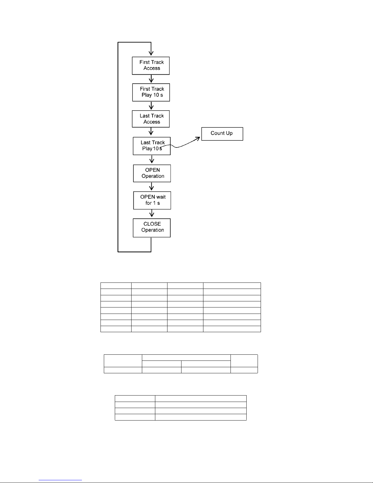
CD Traverse Test
Mode
To check for the traverse unit
operation. In this mode, the
first & last track is access &
read. (TOC). It fails when
TOC is not completed by 10s
or the traverse is out of
focus. for more than 2s
Refer to 8.3.6 for more
information
In Doctor Mode:
Press [ ] follow by [1] &
then [2]
butt
on on the remote control of HC35.
To cancel, press [0] button on remote
control. It returns Doctor Mode.
To exit Doctor Mode, press button on main unit or on the remote control
of HC35.
The counter will increment by 1 until reach
99999999
22
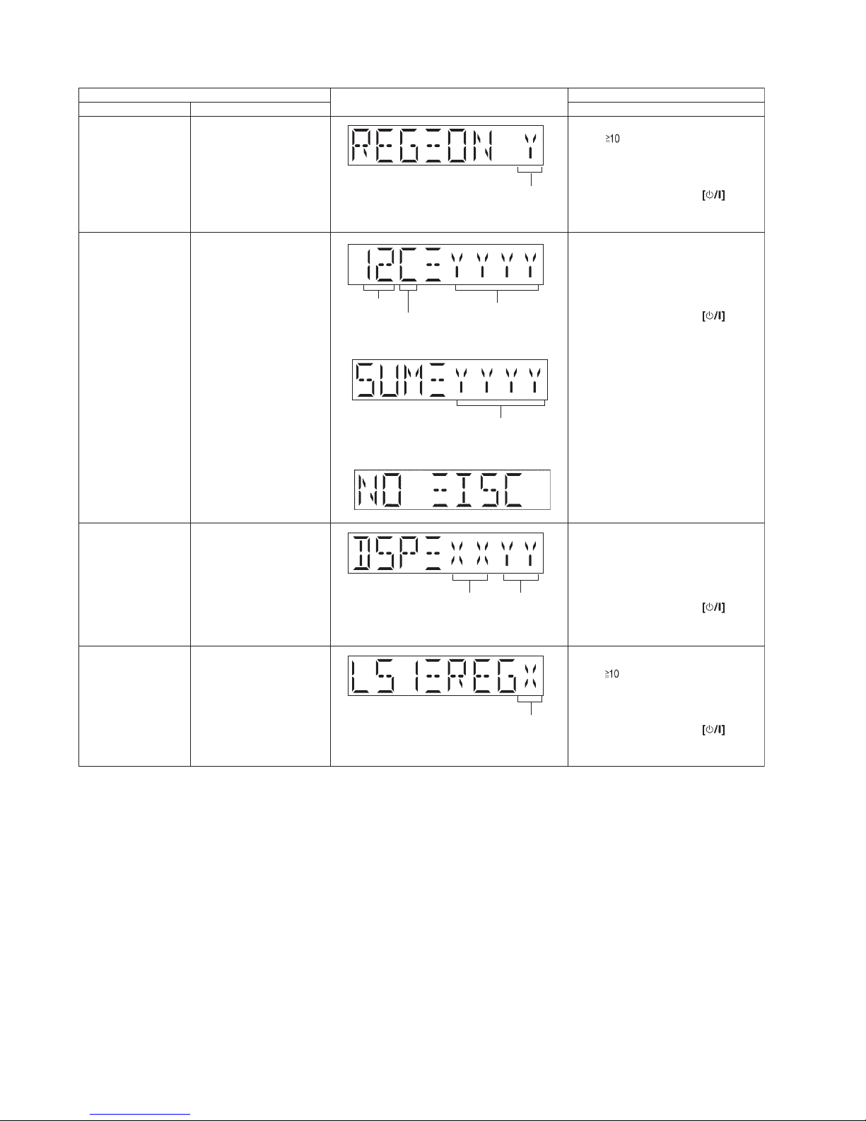
8.3.4. Doctor Mode Table 4
noitarepOyeKyalpsiDLFmetI
Mode Name Description Front Key
In Doctor Mode:
Press [ ] follow by [1] & then [6]
button on the remote control of HC35.
To cancel, press [0] button on remote
control. It returns Doctor Mode.
To exit Doctor Mode, press button on main unit or on the remote control
of HC35.
In Doctor Mode:
Press [4] button on the remote control
of HC35.
To cancel, press [0] button on remote
control. It returns Doctor Mode.
To exit Doctor Mode, press button on main unit or on the remote control
of HC35.
Region Checking
To check Region setting of
unit.
Refer to 8.3.8 for the
Region
Setting destination
Region Setting destination
CD LSI 947 Version
Check
To check CD LSI Version
No. & checksum correction
Yamaha DSP Version
Check
To check DSP Firmware
mode & Version No.
Model setting
To check Model Setting.
Refer to 8.3.9 for the Model
Setting
In Doctor Mode:
Press [6] button on the remote control of
HC35.
To cancel, press [0] button on remote
control. It returns Doctor Mode.
To exit Doctor Mode, press button on main unit or on the remote control
of HC35.
Year of sales
ROM type
Running version
number
Firmware Version No
(00~FF)
Firmware Mode
(00~FF)
In Doctor Mode:
Press [ ] follow by [1] & then [8]
button on the remote control of HC35.
To cancel, press [0] button on remote
control. It returns Doctor Mode.
To exit Doctor Mode, press button on main unit or on the remote control
of HC35.
Model Setting
Check sum display (HEX)
The display will appear after 2s,
The [NO DISC] display will appear after 2s,
23
8.3.5. Mecha Sliding Panel Reliability
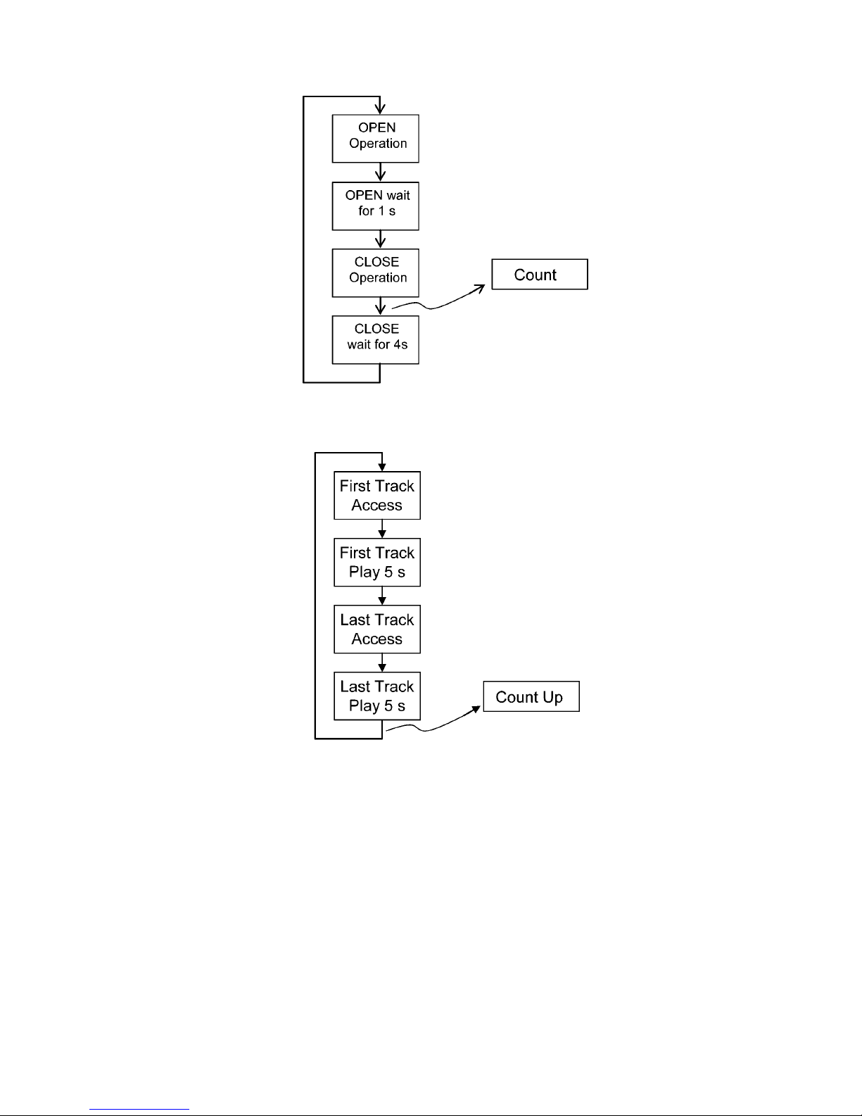
8.3.6. CD Traverse Test (For CD)
24
8.3.7. CD Combination Test (For CD)
8.3.8. Region Check Table (For Tuner)
8.3.9. Model setting
8.3.10. SMPS Region Table
Note : Please refer to Section 15 (Printed Circuit Board Diagrams) for the SMPS P.C.B and Main P.C.B part number.
Region Model Series Country
1 HC37 P/PC North America
2 (D) HC37 Japan Japan
3 HC37 EE E. Europe
4 HC37 EB/EG/EF/EC UK, Germany, France
5 HC37 DBEB UK
6 HC37 GT/GK/GS/PU S.E. Asia
7 HC37 GN Oceania
Region No. Function Model
With iPod With Shock Proof
S0 O O HC37
SMPS Block No. Main P.C.B. Series
AJapan
BP/PC
C Others
25
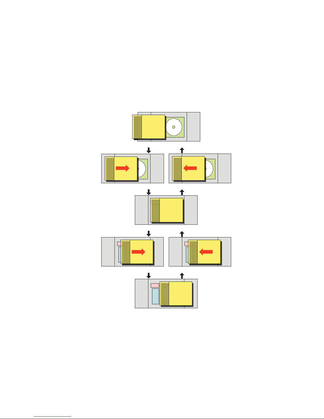
8.4. Sliding Door Operation
8.4.1. Basic Operation
1. The sliding open and close operation of the electric panel is done with [CD OPEN/CLOSE] key & [iPod OPEN/CLOSE] key on
the main set or remote control.
2. The [CD OPEN/CLOSE] key & [iPod OPEN/CLOSE] key valid during standby condition.
3. When in iPod OPEN condition, the door does not move by pressing [CD OPEN/CLOSE] key.
Note : Same behaviors during closing/opening.
4. When in CD OPEN condition, the door does not move by pressing [iPod OPEN/CLOSE] key.
Note : Same behaviors during closing/opening.
5. During playback CD, open the door after stopping playback
6. If the door is pushed in the direction from CD open to neutral, the door i s closed. It is equivalent to pressing [CD OPEN/
CLOSE] key.
7. CD/iPod [OPEN/CLOSE] key is detected based on trigger up (key release) timing.
SP SP
iPod
FL
SP SP
iPod
FL
SP SP
iPod
FL
SP SP
iPod
FL
SP SP
iPod
FL
SP SP
iPod
FL
SP SP
iPod
FL
SP SP
iPod
FL
SP SP
iPod
FL
SP SP
iPod
FL
SP SP
iPod
FL
SP SP
iPod
FL
SP SP
iPod
FL
SP SP
iPod
FL
SP SP
iPod
FL
SP SP
iPod
FL
SP SP
iPod
FL
SP SP
iPod
FL
SP SP
iPod
FL
SP SP
iPod
FL
SP SP
iPod
FL
SP SP
iPod
FL
SP SP
iPod
FL
SP SP
iPod
FL
SP SP
iPod
FL
CD Open
in the middle of closing CD in the middle of opening CD
Neutral
in the middle of opening iPod in the middle of closing iPod
iPod Open

26
9 Service Fixture & Tools
Prepare service tools before process service position.
Ref. No. Service Tools Remarks
SFT1 Main P.C.B. (CN6006) - CD Servo P.C.B. (CN7002) REE1712 (30P FFC)
SFT2 Main P.C.B. (CN1100) - SMPS P.C.B. (P1700) REX1538 (7P Wire)
27
10 Disassembly and Assembly Instructions
Caution Note:
• This section describes the disassembly and/or assembly procedures for all major printed circuit boards & main components for the unit. (You may refer to the section of “Main components and P.C.B Locations” as described in the service
manual)
• Before carrying out the disassembly process, please ensure all the safety precautions & procedures are followed.
• During the disassembly and/or assembly proc ess, please handle with care as there may be chassis components with
sharp edges.
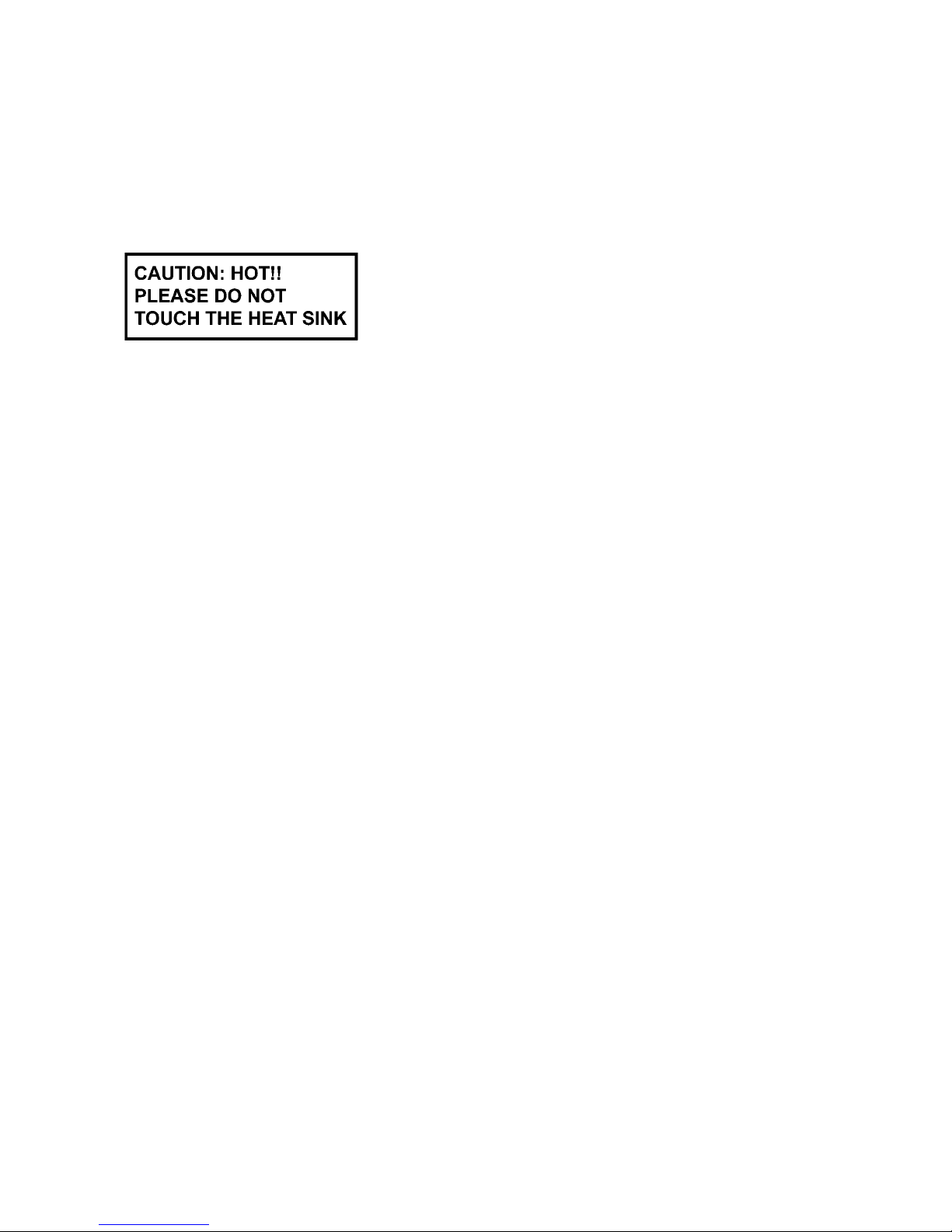
• Avoid touching heatsinks due to its high temperature after prolong use. (See caution as described below)
• During disassembly and assembly, please ensure proper service tools, equipments or jigs is being used.
• During replacement of component parts, please refer to the section of “Replacement Parts List” as described in the service manual.
• Select items from the following indexes when disassembly or replacement are required.
• Disassembly of Base Stand Assembly
• Replacement of Door Assembly
• Replacement of Front Ornament Unit (L) & (R)
• Disassembly of Front Panel Block
• Replacement of iPod Block
• Disassembly of Interlock Switch P.C.B.
• Disassembly of Remote Sensor P.C.B.
• Replacement of Gear Box Assembly
• Disassembly of Motor P.C.B.
• Disassembly of Belt & Pulley Gear
• Disassembly of Motor Assembly
• Disassembly of Centering Spring & Centering Stopper
• Disassembly of Lever Spring, Trigger Lever & Driver Gear A
• Disassembly of SW Lever, Relay Gear & Driver Gear B
• Disassembly of Shutter & Shutter Spring
• Disassembly of Upper Guide Rail & Top Ornament
• Disassembly of Bottom Ornament
• Disassembly of Lower Guide Rail
• Disassembly of SMPS P.C.B.
• Replacement of Diode (D1700)
• Disassembly of Panel P.C.B. & Button Ornament Unit
• Disassembly of Button P.C.B.
• Disassembly of Button Ornament
• Disassembly of CD Mechanism
• Disassembly of CD Servo P.C.B.
• Disassembly of Jack Lid
• Disassembly of Main P.C.B.
• Disassembly of Passive Radiator (SP3 & SP4)
• Disassembly of Front Speaker (SP1)
• Disassembly of Front Speaker (SP2)
• Disassembly of Passive Radiator (SP5)
• Disassembly of Passive Radiator (SP6)
28
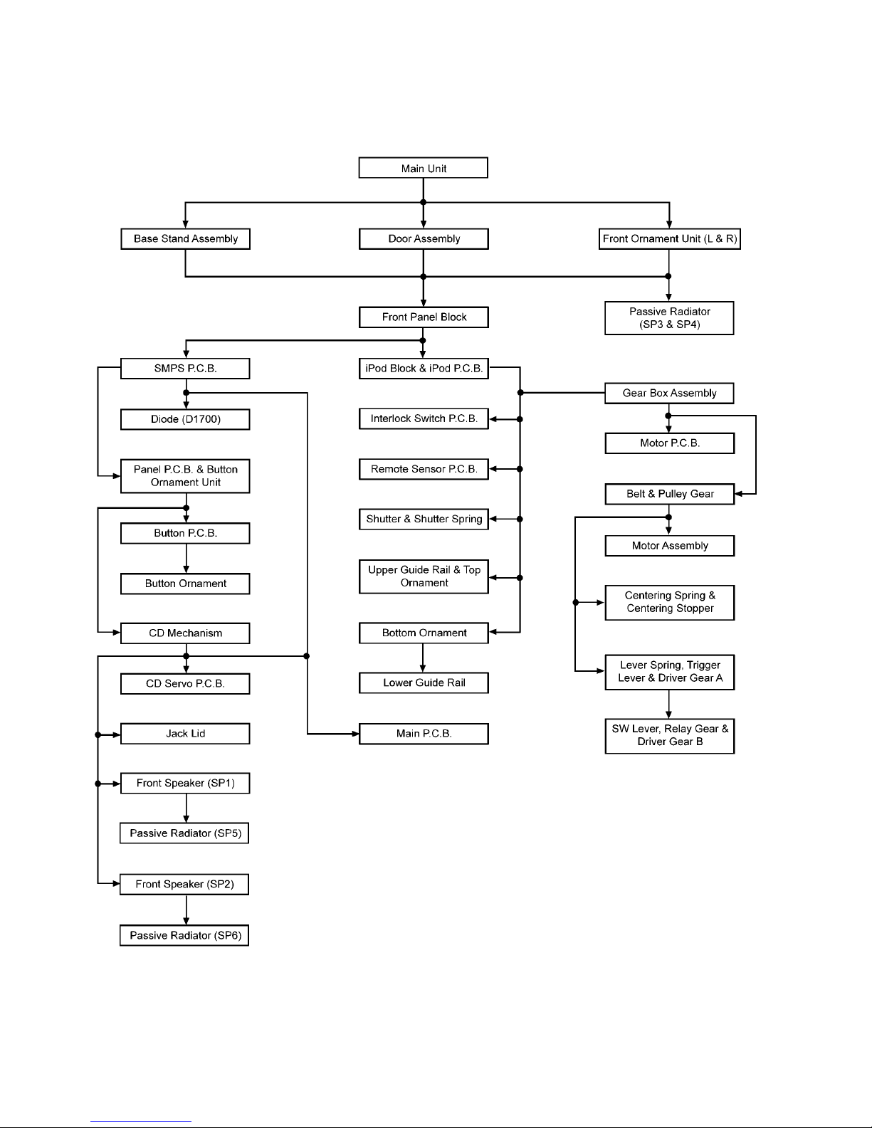
10.1. Disassembly flow chart
The following chart is the procedure for disassembling the casing and inside parts for internal inspection when carrying out the servicing.
To assemble the unit, reverse the steps shown in the chart below.
29
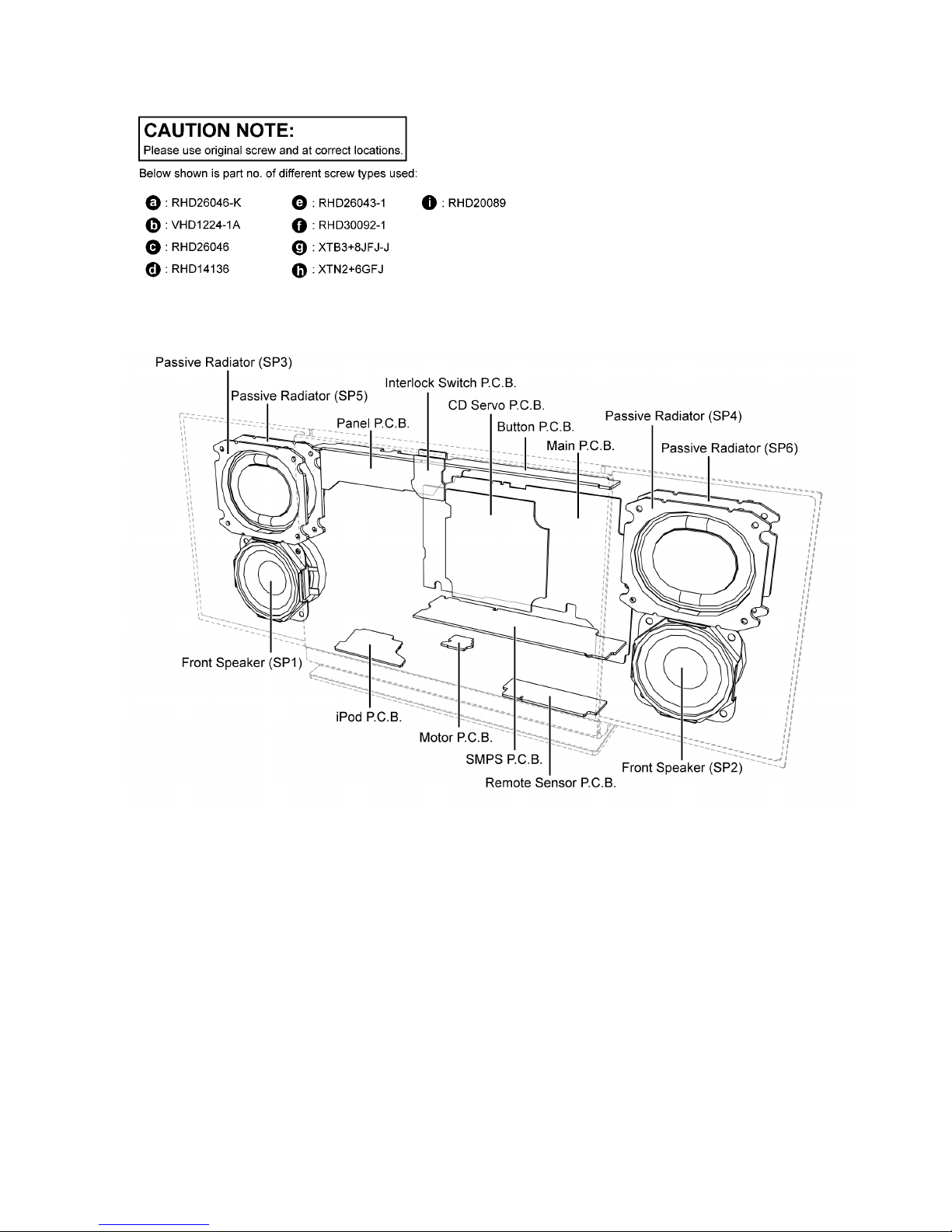
10.2. Types of Screws
10.3. Main Parts Location Diagram
30
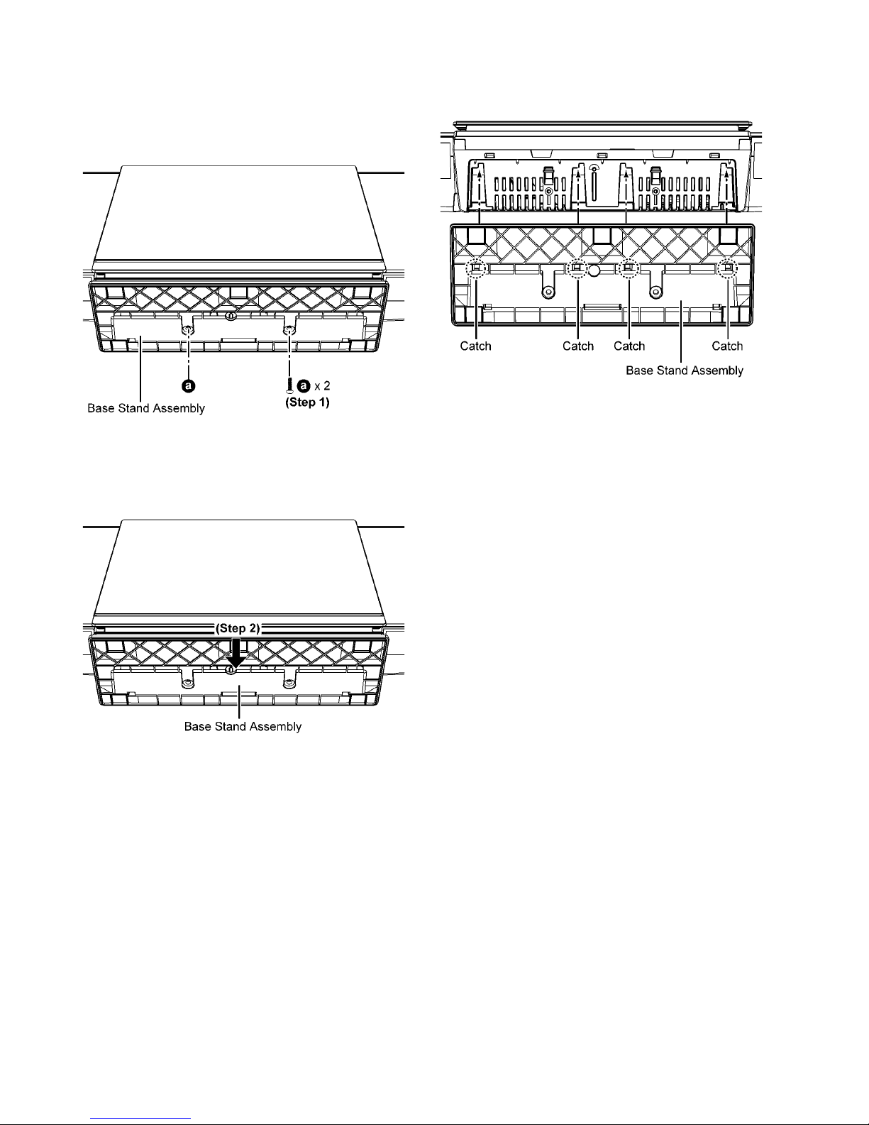
10.4. Disassembly of Base Stand
Assembly
Step 1 : Remove 2 screws.
Step 2 : Remove the Base Stand Assembly.
Caution : During assembling, ensure a “tack” Sound is
heard when the base Stand Assembly Is fully catch onto
the rear Cabinet.
 Loading...