

Panasonic SCEN-33-PC Service manual
y
y
y
A
r
L
y
A
ORDER NO. MD0703020CE
CD Stereo System
SC-EN33PC
Colour
(S)... Silver Type
System
SC-EN33PC-S
Main Unit: SA-EN33PC-S
Speakers: SB-EN33APC-S (L) & SB-EN33PC-S (R)
A6
Specifications
n AMPLIFIERSECTION
FTC OUTPUT POWERboth channel driven simultaneousl
10% total harmonic distortion (THD)
1 kHz 1.8 W per channel
RMS OUTPUT POWERboth channel driven simultaneousl
10% total harmonic distortion (THD)
1 kHz 2 W per channel
Outputimpedance
HEADPHONE 16 W to 32 W
MUSIC PORT 14 kW
Phone Jack
Terminal 3.5 mm stereo
Music Port Jack
Terminal 3.5 mm stereo
n TUNER SECTION
Frequencyrange
FM 87.9 MHz to 107.9 MHz (200 kHz)
87.5 MHz to 108.0 MHz (100 kHz)
AM 520 kHz to 1710 kHz (10 kHz)
n CD SECTION
Disc played [8cm (3”) or 12cm (5”)]
(1) CD-Audio (CD-DA)
(2) CD-R/RW (CD-DA, MP3)
(3) MP3
Sampling frequenc
CD 44.1 kHz
MP3 32 kHz, 44.1 kHz, 48 kHz
Bit rate
MP3 32 kbps to 384 kbps
Decoding 16/20/24 bit linear
Pick up
Wavelength 785 nm
Laser power CLASS 1
udioOutput(Disc)
Number ofchannels 2 channel
Frequencyresponse 20 Hz to 20 kHz (+1, -2 dB)
Wow and flutter Below measurement limit
Digital filter 8
D/Aconverte
n GENERA
Power suppl
Power consumption 30 W
Dimension (WxHXD) 220mmx236mmx146 mm
(8 21/32” x 9 9/32” x 5 3/4”)
Mass
With speakers 3.57 kg (7.87 lbs)
Withoutspeakers 1.27 kg (2.80 lbs)
n SPEAKERSECTION
MASH (1 bit DAC)
C120V,60Hz
© 2007 Matsushita Electric Industrial Co. Ltd.. All
rights reserved. Unauthorized copying and
distribution is a violation of law.
e
A
X
SC-EN33PC
Typ
Speaker(s) 8 cm (5 1/2”) cone type 6 W
Impedance 6 W
Inputpower 6(M
Dimension (WxHxD) 121 mmx236 mmx146 mm
1Way, 1 speaker system
(4 3/4” x 9 9/32” x 5 3/4”)
Power consumption in standbymode:
Notes:
· Specifications are subject to change without notice.
)
· Mass and dimensions are approximate.
CONTENTS
Page Page
11 Service Positions
1 Safety Precautions
1.1. General Guidelines
1.2. Caution for fuse replacemen t
1.3. Before repair and adjustment
1.4. Protection Circuitry
1.5. Safety Parts Information
2 Prevention of Electro Static Discharge (ESD) to
Electrostatically Sensitive (ES) Devices
3 Precaution of laser diode
4 Handling Precautions For Traverse Unit
5 About Lead Free Solder (PbF)
5.1. Service caution based on legal restrictions
6 Accessories
7 Operation Procedures
7.1. Remote Control Key Buttons Operations
7.2. Main Unit Key Buttons Operations
7.3. Connection
8 Self diagnosis and special mode setting
8.1. Service Mode Summary Table
8.2. Service Mode Table 1
8.3. Error Code Table 1
9 Assembling and Disassembling
9.1. Caution
9.2. Disassembly flow chart
9.3. Main Components & P.C.B. Locations
9.4. Disassembly of Rear Cabinet
9.5. Disassembly of Panel P.C.B. & LED P.C.B.
9.6. Disassembly of Main P.C.B., Sensor P.C.B. & Tuner
P.C.B.
9.7. Disassembly of Switch P.C.B. and Traverse Unit
9.8. Disassembly of Power Switch P.C.B. & Tact Switch P.C.B.
9.9. Replacement of Traverse Cover
9.10. Disassembly of CD Servo P.C.B.
9.11. Disassembly of Motor Unit & Motor P.C.B.
9.12. Disassembly of CD Block & CD Lid
9.13. Disassembly of Speakers
10 Service Fixture and Tools
4
4
5
5
5
5
6
7
7
9
9
10
11
11
11
12
13
13
13
16
17
17
18
19
20
20
20
21
21
22
23
23
24
25
29
11.1. Check and Repair of CD Servo P.C.B.
11.2. Check and repair of Main P.C.B., Sensor P.C.B., Tuner
P.C.B., Motor P.C.B., Panel P.C.B., LED P.C.B., Power
Switch P.C.B., Tact Switch P.C.B. & Switch P.C.B.
12 Voltage and Waveform Chart
12.1. Main P.C.B.
12.2. CD Servo P.C.B.
12.3. Motor P.C.B.
12.4. Panel P.C.B.
12.5. Tuner P.C.B.
12.6. Waveform Chart
13 Wiring Connection Diagram
14 Block Diagram
14.1. CD Servo
14.2. Tuner
14.3. Main (1/2), Transformer & Sensor
14.4. Main (2/2), Panel, LED, Power Switch, Tact Switch, Switch
& Motor
15 Notes of Schematic Diagrams
16 Schematic Diagram
16.1. (A) CD Servo Circuit
16.2. (B) Tuner Circuit
16.3. (C) Main Circuit
16.4. (D) Panel Circuit, (E) LED Circuit, (F) Power Switch
Circuit, (G) Tact Switch Circuit & (H) Switch Circuit
16.5. (I) Motor Circuit, (J) Sensor Circuit & (K) Transforme r
Circuit
17 Printed Circuit Board
17.1. (A) CD Servo P.C.B. & (B) Tuner P.C.B.
17.2. (C) Main P.C.B.
17.3. (D) Panel P.C.B., (E) LED P.C.B., (F) Power Switch
P.C.B., (G) Tact Switch P.C.B., (H) Switch P.C.B., (I)
Motor P.C.B., (J) Sensor P.C.B. & (K) Transforme r P.C.B.
18 Illustration of ICs, Transistors and Diodes
19 Terminal Function of IC's
2.0 W (appx.)
29
30
31
32
32
33
33
33
33
34
35
37
37
38
39
40
41
43
44
45
46
49
50
51
52
53
54
55
56
2

19.1. IC801 (MN101EF16ZXW) Servo Processor,Digital Signal
Processor/Digital filter and D/A Converter
20 Exploded Views
20.1. Cabinet Parts Location
56
57
20.2. Packaging
21 Replaceme nt Parts List
SC-EN33PC
57
59
61
3
SC-EN33PC
1 Safety Precautions
1.1. General Guidelines
1. When servicing, observe the original lead dress. If a short circuit is found, replace all parts which have been overheated or
damaged by the short circuit.
2. After servicing, ensure that all the protective devices such as insulation barriers and insulation papers shields are properly
installed.
3. After servicing, check for leakage current checks to prevent from being exposed to shock hazards.
(This “Safety Precaution” is applied only in U.S.A.)
1. Before servicing, unplug the power cord to prevent an electric shock.
2. When replacing parts, use only manufacturer’s recommended components for safety.
3. Check the condition of the power cord. Replace if wear or damage is evident.
4. After servicing, be sure to restore the lead dress, insulation barriers, insulation papers, shields, etc.
5. Before returning the serviced equipment to the customer, be sure to make the following insulation resistance test to prevent the
customer from being exposed to a shock hazard.
1.1.1. Leakage Current Cold Check
1. Unplug the AC cord and connect a jumper between the two prongs on the plug.
2. Using an ohmmeter measure the resistance value, between the jumpered AC plug and each exposed metallic cabinet part on
the equipment such as screwheads, connectors, control shafts, etc. When the exposed metallic part has a return path to the
chassis, the reading should be between 1MW and 5.2MW .
When the exposed metal does not have a return path to the chassis, the reading must be
.
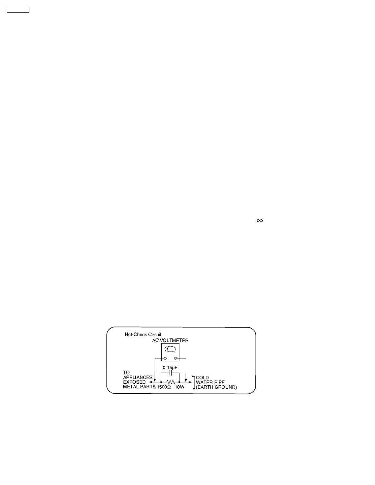
1.1.2. Leakage Current Hot Check (See Figure 1)
1. Plug the AC cord directly into the AC outlet. Do not use an isolation transformer for this check.
2. Connect a 1.5kW , 10 watts resistor, in parallel with a 0.15µF capacitor, between each exposed metallic part on the set and a
good earth ground such as a water pipe, as shown in Figure 1.
3. Use an AC voltmeter, with 1000 ohms/volt or more sensitivity, to measure the potential across the resistor.
4. Check each exposed metallic part, and measure the voltage at each point.
5. Reverse the AC plug in the AC outlet and repeat each of the above measurements.
6. The potential at any point should not exceed 0.75 volts RMS. A leakage current tester (Simpson Model 229 or equivalent) may
be used to make the hot checks, leakage current must not exceed 1/2 milliamp. Should the measurement is out of the limits
specified, there is a possibility of a shock hazard, and the equipment should be repaired and rechecked before it is returned to
the customer.
Fig. 1
4
SC-EN33PC
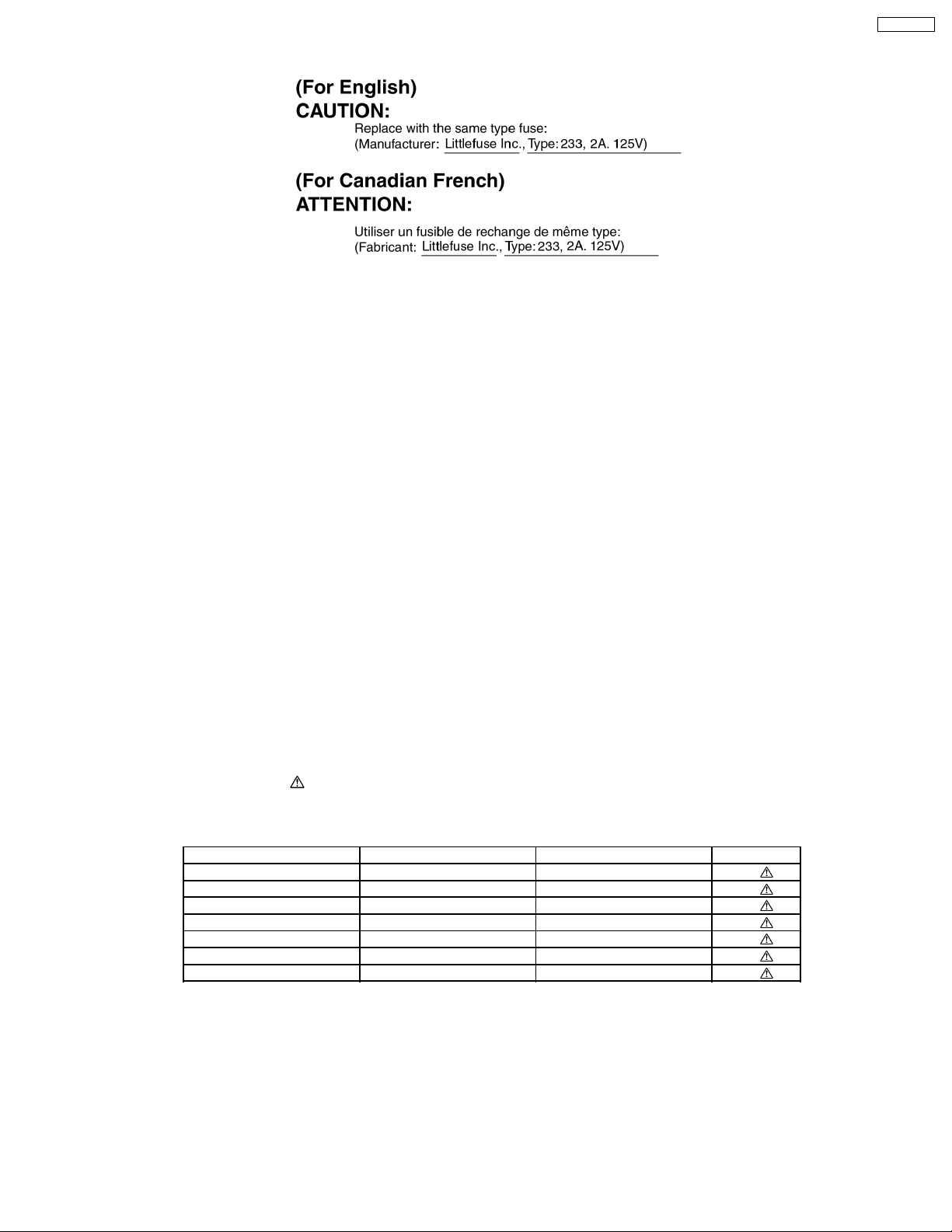
1.2. Caution for fuse replacement
1.3. Before repair and adjustment
Disconnect AC power, discharge Power Capacitors C611 and C616 through a 10W , 1W resistor to ground.
DO NOT SHORT-CIRCUIT DIRECTLY (with a screwdriver blade, for instance), as this may destroy solid state devices.
After repairs are completed, restore power gradually using a variac, to avoid overcurrent.
Current consum ption at AC 120V, 60 Hz in NO SIGNAL mode (volume min at CD mode) should be ~ 135mA.
1.4. Protection Circuitry
The protection circuitry may have operated if either of the following conditions are noticed:
· No sound is heard when the power is turned on.
· Sound stops during a performance.
The function of this circuitry is to prevent circuitry damage if, for example, the positive and negative speaker connec tion wires are
“shorted”, or if speaker systems with an impedance less than the indicated rated impedance of the amplifier are used.
If this occurs, follow the procedure outlines below:
1. Turn off the power.
2. Determine the cause of the problem and correct it.
3. Turn on the power once again after one minute.
Note :
When the protection circuitry functions, the unit will not operate unless the power is first turned off and then on again.
1.5. Safety Parts Information
Safety Parts List:
There are special components used in this equipment which are important for safety.
These parts are marked by
should be replaced with manufacturer’s specified parts to prevent shock, fire or other hazards. Do not modify the original design
without permission of manufacturer.
Reference No. Part No. Part Name & Description Remarks
A2 K2CB2CB00018 AC CORD [M]
F901 K5D202APA008 FUSE [M]
IP601 K5G302AA0002 FUSE PROTECTOR [M]
IP602 K5G251A00008 FUSE PROTECTOR [M]
JK901 K2AB2B000007 FUSE [M]
L901 ELF15N035AN LINE FILTER [M]
T901 G4C5ABD00006 TRANSFORMER [M]
in the Schematic Diagrams & Replacement Parts List. It is essential that these critical parts
Table 1
5

SC-EN33PC
2 Prevention of Electro Static Discharge (ESD) to
Electrostatically Sensitive (ES) Devices
Some semiconductor (solid state) devices can be damaged easily by electricity. Such components commonly are called
Electrostatically Sensitive (ES) Devices. Examples of typical ES devices are integrated circuits and some field-effect transistors and
semiconductor “chip” components. The following techniques should be used to help reduce the incidence of component damage
caused by electro static discharge (ESD).
1. Immediately before handling any semiconductor component or semiconductor-equiped assembly, drain off any ESD on your
body by touching a known earth ground. Alternatively, obtain and wear a comme rcially available discharging ESD wrist strap,
which should be removed for potential shock reasons prior to applying power to the unit under test.
2. After removing an electrical assembly equiped with ES devices, place the assembly on a conductive surface such as aluminium
foil, to prevent electrostatic charge build up or exposure of the assembly.
3. Use only a grounded-tip soldering iron to solder or unsolder ES devices.
4. Use only an anti-static solder remover device. Some solder removal devices not classified as “anti-static (ESD protected)” can
generate electrical charge to damage ES devices.
5. Do not use freon-propelled chemicals. These can generate electrical charges sufficient to damage ES devices.
6. Do not remove a replacement ES device from its protective package until immediately before you are ready to install it. (Most
replacement ES devices are packaged with leads electrically shorted together by conductive foam, aluminium foil or
comparable conductive material).
7. Immediately before removing the protective material from the leads of a replacement ES device, touch the protective material
to the chassis or circuit assembly into which the device will be installed.
Caution
Be sure no power is applied to the chassis or circuit, and observe all other safety precautions.
8. Minimize body motions when handling unpackaged replacement ES devices. (Otherwise harmless motion such as the brushing
together of your clothes fabric or the lifting of your foot from a carpeted floor can generate static electricity (ESD) sufficient to
damage an ES device).
6
SC-EN33PC
3 Precaution of laser diode
CAUTION:
This unit utilizes a class 1 laser diode in the optical pickup unit .
Invisible laser radiation is emitted from the optical pickup lens.
Wavelength: 780nm
When the unit is turned on:
1. Do not look directly into the optical pickup lens.
2. Do not use optical instruments to look at the optical pickup lens.
3. Do not adjust the preset variable resistor on the optical pickup lens.
4. Do not disassemble the optical optical pickup unit.
5. If the optical pickup is replaced, use the manufacturer’s specified replacement pickup only.
6. Use of control or adjustments or performance of procedures other than those specified herein may result in hazardous radiation
exposure.
CAUTION!
THIS PRODUCT UTILIZES A LASER.
USE OF CONTROLS OR ADJUSTMENTS OR PERFORMANCE OF PROCEDURES OTHER THAN THOSE SPECIFIED HEREIN MAY RESULT
IN HAZARDOUS RADIATION EXPOSURE.
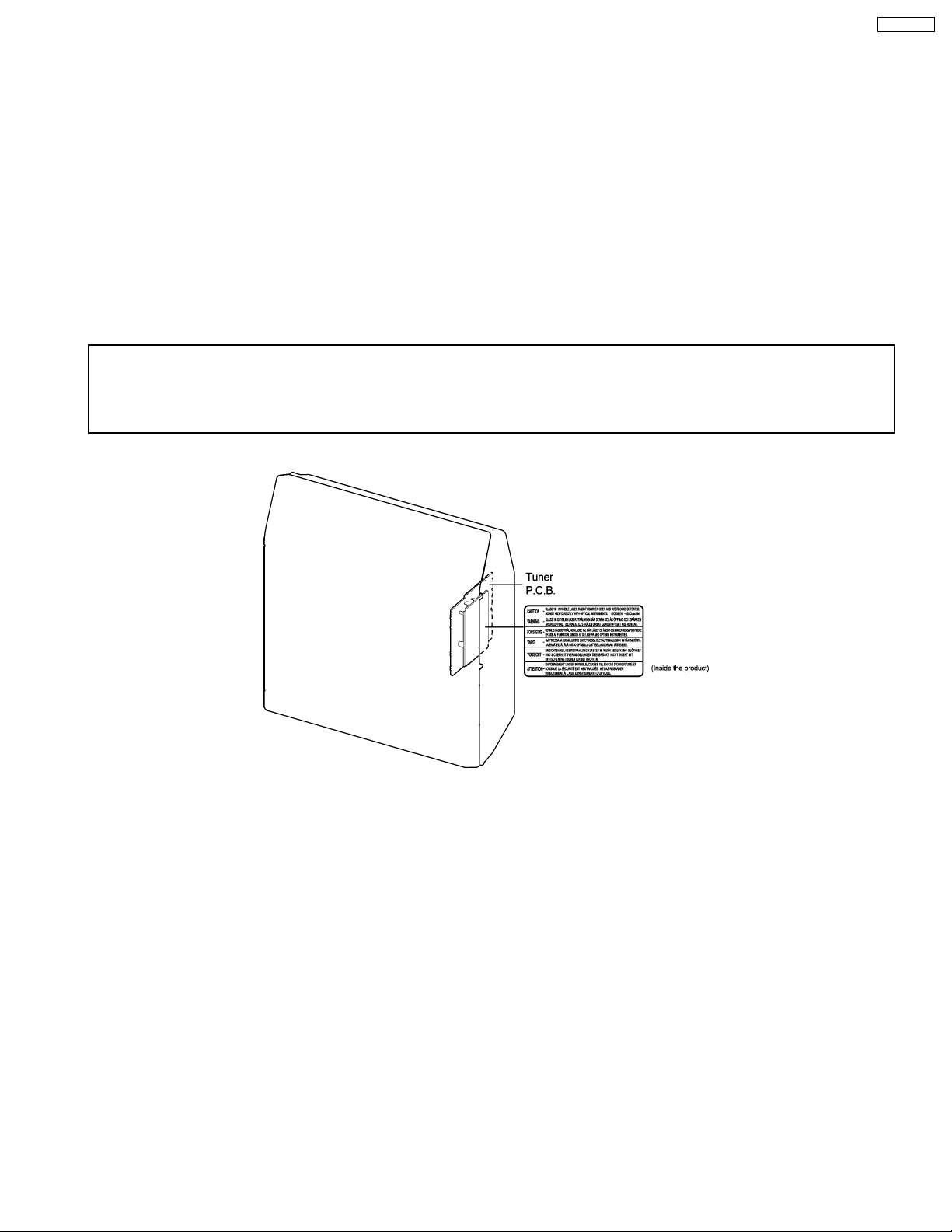
n Use of caution label (Except for U.S.A.)
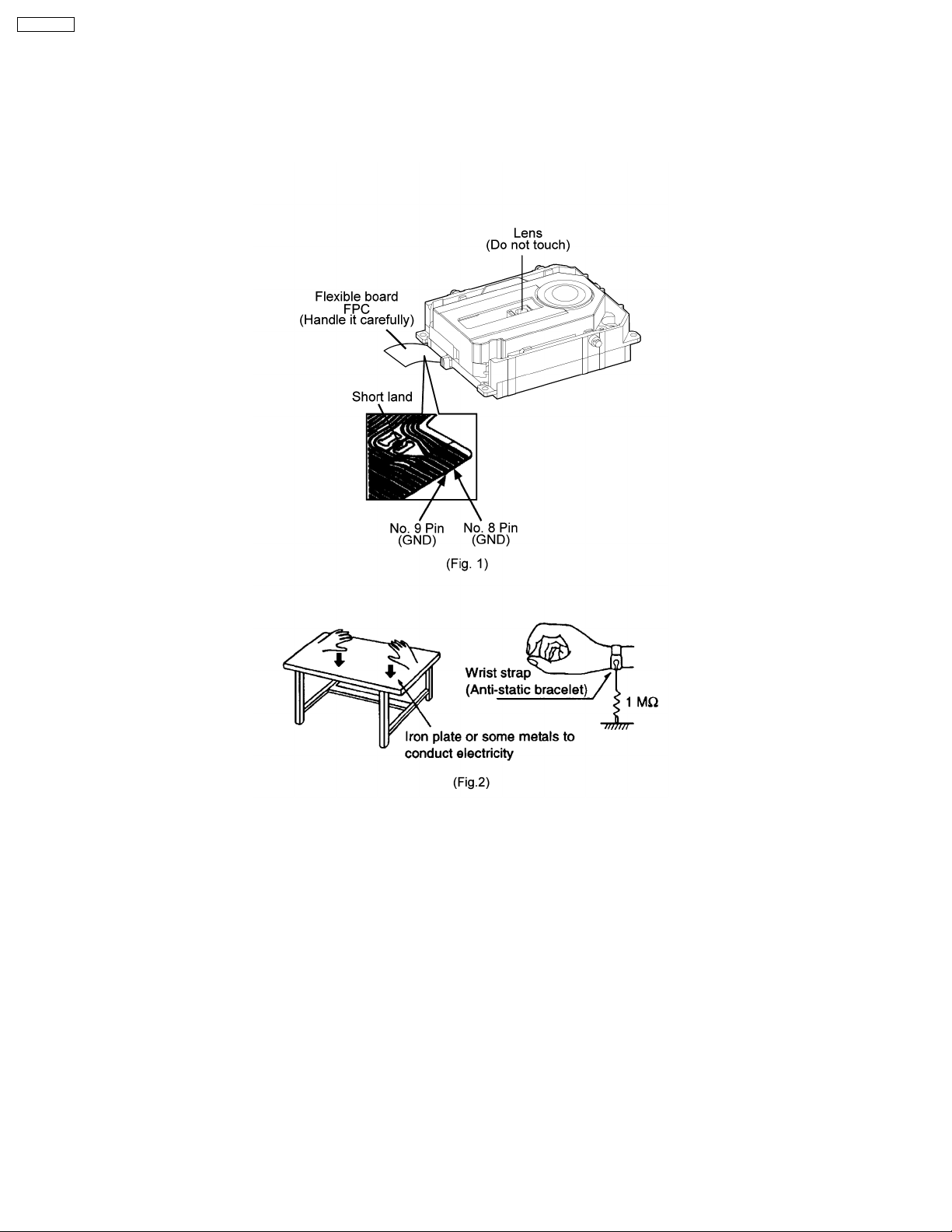
4 Handling Precautions For Traverse Unit
The laser diode in the traverse deck (optical pickup) may break down due to potential difference caused by the static electricity of
clothes or our human body.
So, be careful of electrostatic breakdown during repair of the traverse deck (optical pickup).
· Way of handling the traverse deck (optical pickup)
1. Do not subject the traverse deck (optical pickup) to static electricity as it is extremely sensitive to electrical shock.
2. To prevent the breakdown of the laser diode, an antistatic shorting pin is inserted into the flexible board (FFC board). (Fig. 1)
3. Take care not to apply excessive stress to the flexible board (FFC board). When removing or connecting the short pin, finish
the job in as short time as possible.
4. Do not turn the variable resistor (laser power adjustment). It has already been adjusted.
Grounding for electrostatic breakdown prevention
1. Human body grounding. (Fig. 2)
Use the anti-static wrist strap to discharge the static electricity from your body.
2. Work table grounding. (Fig. 2)
Put a conductive material (sheet) or steel sheet on the area where the traverse deck (optical pickup) is place, and ground the
sheet.
7
SC-EN33PC
Caution :
The static electricity of your clothes will not be grounded through the wrist strap. So, take care not to let your clothes touch the
traverse deck (optical pickup).
Caution when replacing the Traverse Deck
The traverse deck has a short point shorted with solder to protect the laser diode against electrostatics breakdown. Be sure to
remove the solder from the short point before making connections.
8
SC-EN33PC
5 About Lead Free Solder (PbF)
5.1. Service caution based on legal restrictions
5.1.1. General description about Lead Free Solder (PbF)
The lead free solder has been used in the mounting process of all electrical components on the printed circuit boards used for this
equipment in considering the globally environmental conservation.
The normal solder is the alloy of tin (Sn) and lead (Pb). On the other hand, the lead free solder is the alloy mainly consists of tin
(Sn), silver (Ag) and Copper (Cu), and the melting point of the lead free solder is higher approx.30 degrees C (86°F) more than that
of the normal solder.
Definition of PCB Lead Free Solder being used
The letter of “PbF” is printed either foil side or components side on the PCB using the lead free solder.
(See right figure)
Service caution for repair work using Lead Free Solder (PbF)
· The lead free solder has to be used when repairing the equipment for which the lead free solder is used.
(Definition: The letter of “PbF” is printed on the PCB using the lead free solder.)
· To put lead free solder, it should be well molten and mixed with the original lead free solder.
· Remove the remaining lead free solder on the PCB cleanly for soldering of the new IC.
· Since the melting point of the lead free solder is higher than that of the normal lead solder, it takes the longer time to melt
the lead free solder.
· Use the soldering iron (more than 70W) equipped with the temperature control after setting the temperature at 350±30
degrees C (662±86°F).
Recommended Lead Free Solder (Service Parts Route.)
· The following 3 types of lead free solder are available through the service parts route.
RFKZ03D01K-----------(0.3mm 100g Reel)
RFKZ06D01K-----------(0.6mm 100g Reel)
RFKZ10D01K-----------(1.0mm 100g Reel)
Note
* Ingredient: tin (Sn), 96.5%, silver (Ag) 3.0%, Copper (Cu) 0.5%, Cobalt (Co) / Germanium (Ge) 0.1 to 0.3%
9
SC-EN33PC
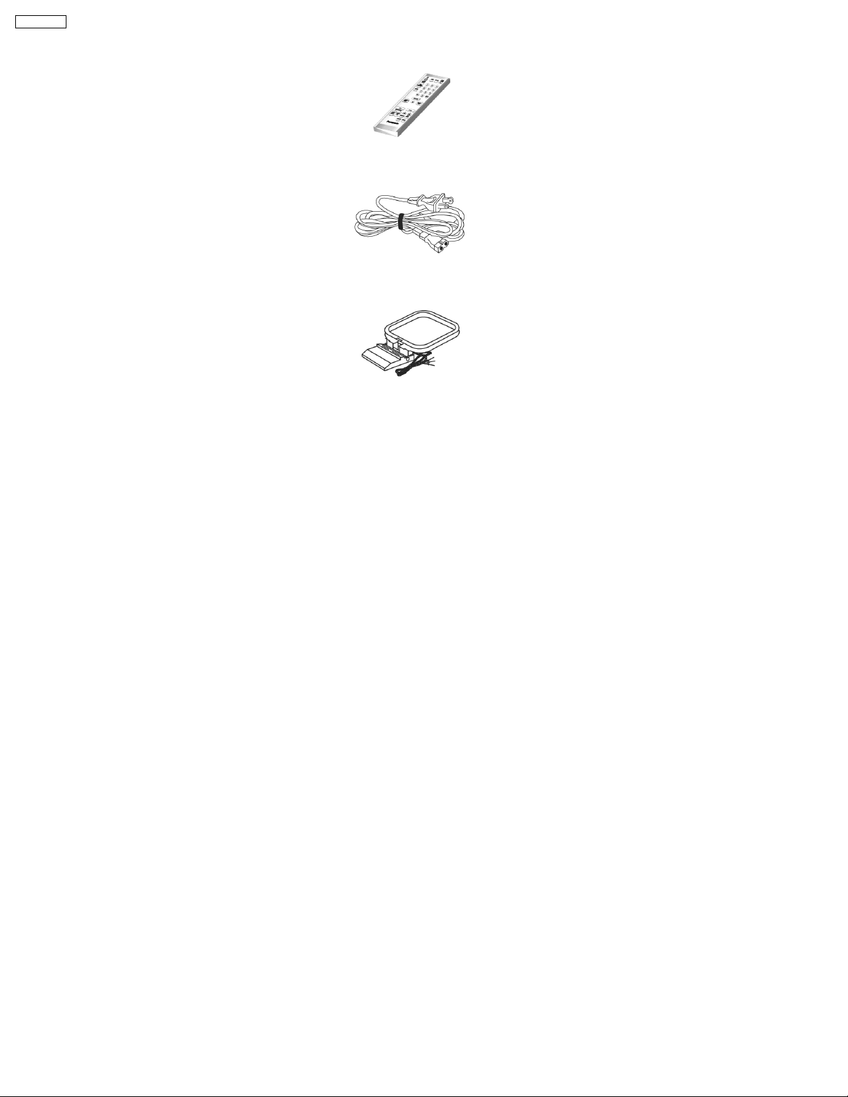
6 Accessories
Remote Control
AC Cord
FM/AM Antenna
10
7 Operation Procedures
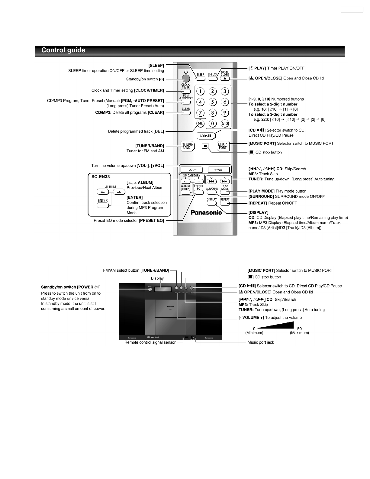
7.1. Remote Control Key Buttons Operations
SC-EN33PC
7.2. Main Unit Key Buttons Operations
11
SC-EN33PC
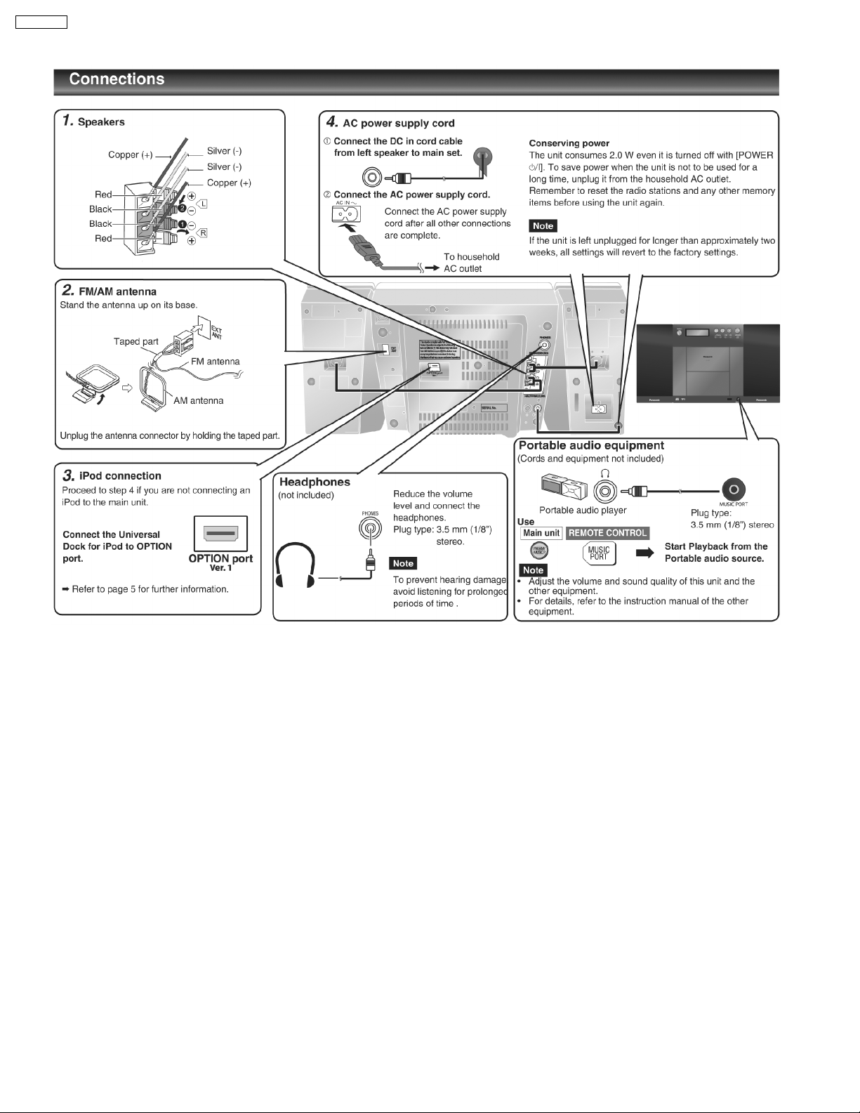
7.3. Connection
12
SC-EN33PC
8 Self diagnosis and special mode setting
This unit is equipped with features of self-diagnostic & special mode setting for checking the functions & reliability.
8.1. Service Mode Summary Table
The service mode can be activated by pressing various button combination on the main unit and remote control unit. Below is the
summary for the various modes for checking:-
Player buttons Remote control unit buttons Application Note
[ ] [4], [7] To enter into doctor mode for various item
checking.
Mode Remote control unit buttons Application Note
Doctor Mode [DIMMER] FL ALL Segment inspection (Refer to the section 8.2 for more
[7], [8], [9] Forced VOL setting (Refer to the section 8.2 for more
[ ], [1], [1] CD Loading Test (Refer to the section 8.2 for more
[ ], [1], [2] CD Traverse Test (Refer to the section 8.2 for more
[ ], [1], [3] CD Combination Test (Refer to the section 8.2 for more
[ ], [1], [4] CD Auto Adjustment Display (Refer to the section 8.2 for more
[SLEEP] Cold Start setting (Refer to the section 8.2 for more
(Refer to the section 8.2 for more
information.)
information.)
information.)
information.)
information.)
information.)
information.)
information.)
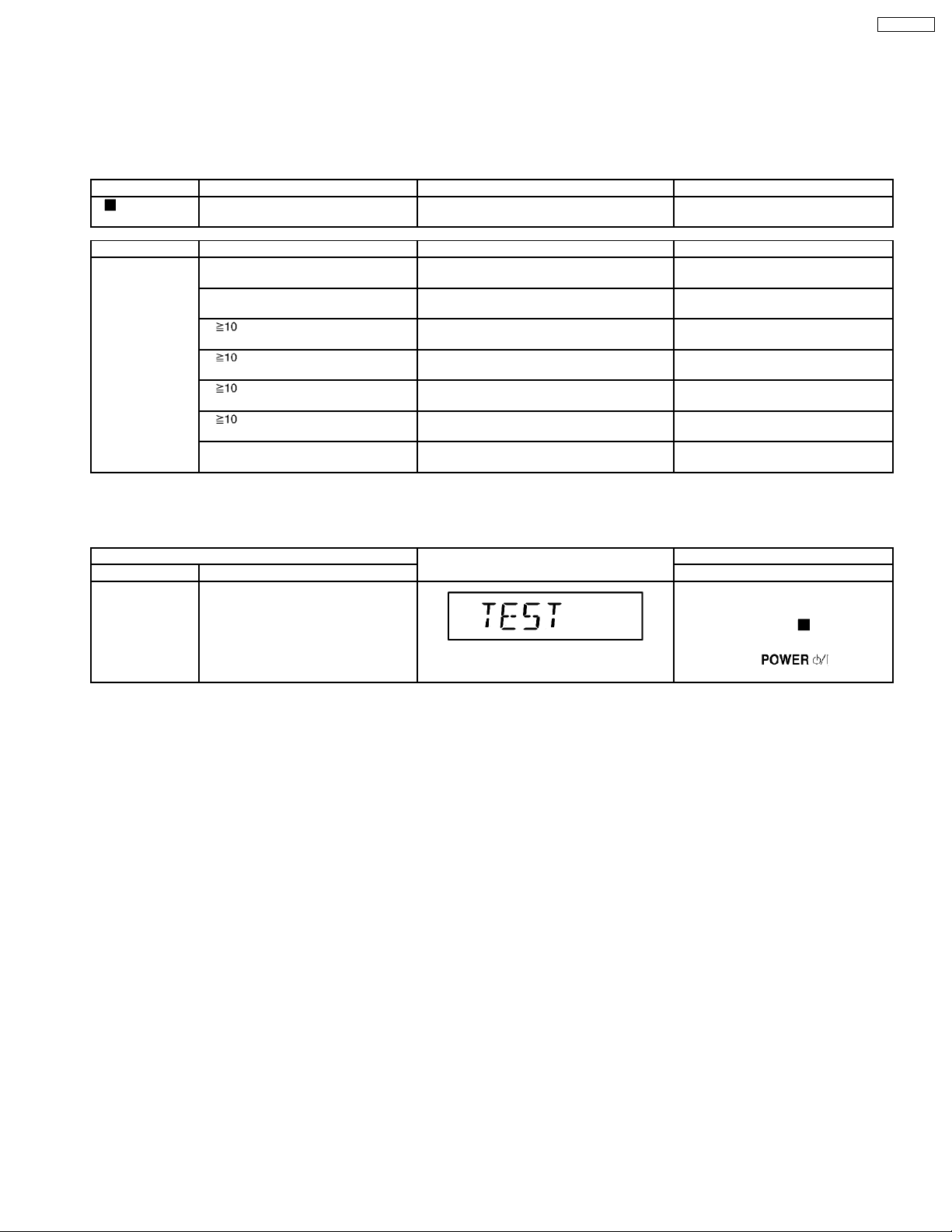
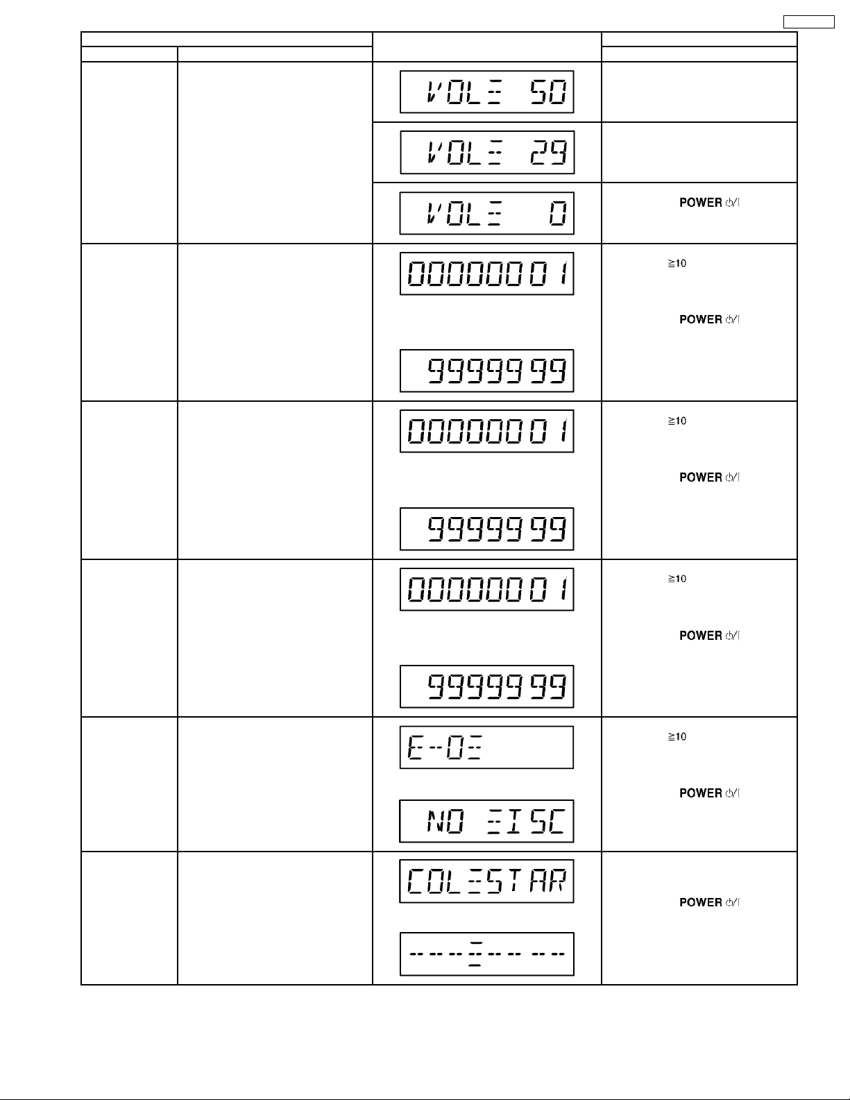
8.2. Service Mode Table 1
Below is the various special modes for checking:-
Item FL Display Key Operation
Mode Name Description Front Key
Self-Diagnostic
Mode
To enter into self diagnostic checking
for main unit.
1. Select [CD] for CD mode (Ensure
no CD inserted.)
2. Press and hold [
seconds follow by [FF]
To exit, press [
main unit or remote control.
] button for 2
] button on
13
SC-EN33PC
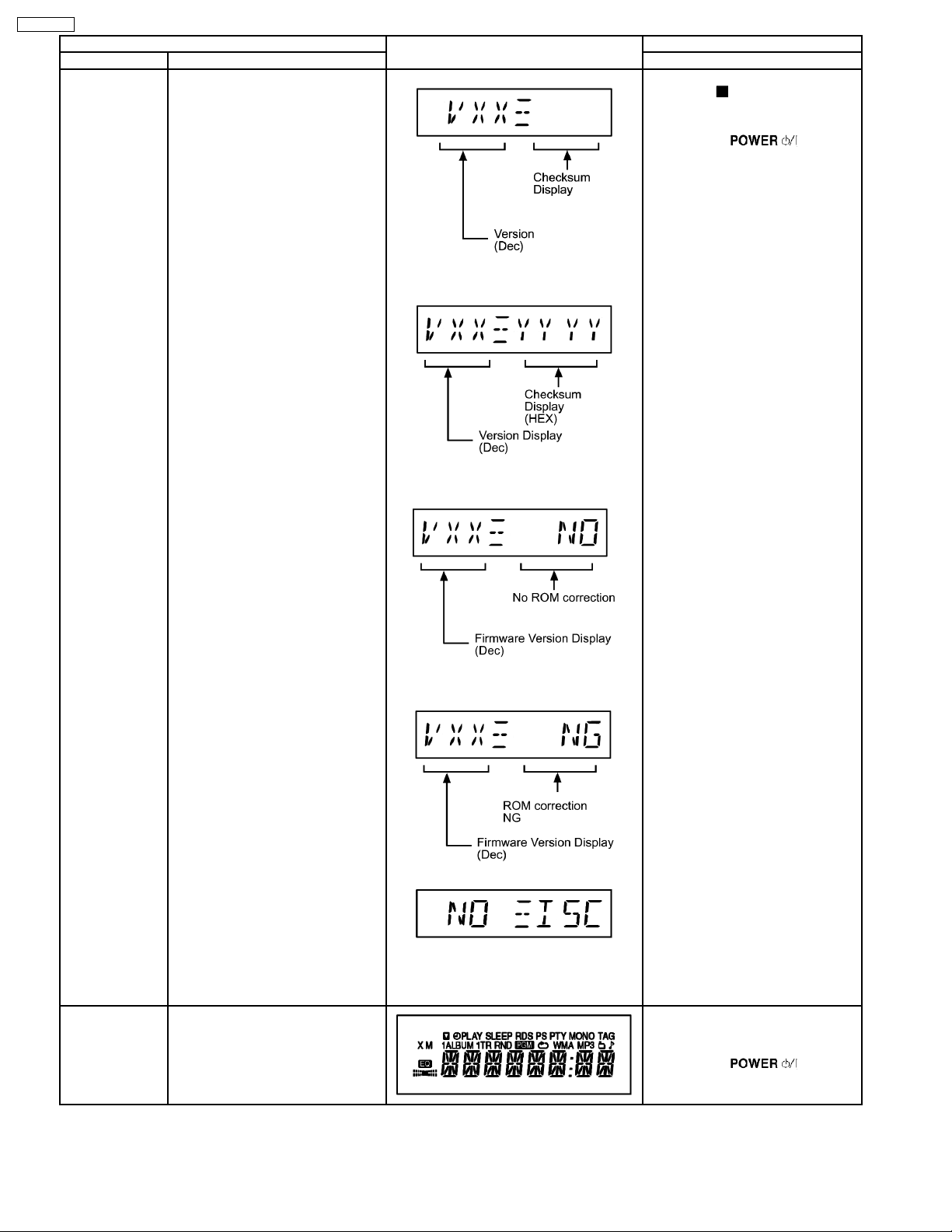
Item FL Display Key Operation
Mode Name Description Front Key
Doctor Mode To enter into Doctor Mode for
checking of various items and
displaying EEPROM and firmware
version.
Note: The micro-processor version as
shown is an example. It will be revise
when there is an updates.
FL Display sequence
Display 1 fi 2
DIsplay 1
Checksum (Condition 1)
When EEPROM IC detected and has ROM
correction.
Checksum (Condition 2)
When EEPROM IC is detected and there is
no ROM correction.
In any mode:
1. Press [
] button on main unit
follow by [4] and [7] on remote
control.
To exit, press [
] button on
main unit or remote control.
FL Display Test To check the FL segments display (All
segments will light up)
Checksum (Condition 3)
When EEPROM IC is detected and has ROM
correction but not working properly.
Display 2
The Check Sum of EEPROM and firmware
version will be display for 1 sec.
* ROM correction
** Firmware version No:
In doctor mode:
1. Press [DIMMER] button on remote
control.
To exit, press [
] button on
main unit or remote control.
14
Item FL Display Key Operation
Mode Name Description Front Key
Volume Setting
Mode
To check for the volume setting of the
main unit. The volume will be
automatically set to its respective
level (in dB). During the mode,
trebble/bass/EQ will be set to “0” dB
& OFF.
In doctor mode:
1. Press [7] button on remote control.
2. Press [8] button on remote control.
SC-EN33PC
CD Loading Test
Mode
CD Traverse Unit
Test Mode
CD Combination
Test Mode
To determine the reliability of CD
Loading unit.
To check for the Open/Close
operation for the CD loading unit. It
fails when there is abnormality in
opening or closing.
To check for the traverse unit
operation. In this mode, the first & last
track is access & read. (TOC). It fails
when TOC is not completed by IOS or
the traverse is out of focus.
A combination of CD loading &
traverse unit test.
The counter will increment by 1 until reach
9999999
fl
The counter will increment by 1 until reach
9999999
fl
The counter will increment by 1 until reach
9999999
fl
3. Press [7] button on remote control.
To exit, press [
main unit or remote control.
In doctor mode:
1. Press [
remote control.
To cancel, press [0] button remote
control.
To exit, press [
main unit or remote control.
In doctor mode:
1. Press [
remote control.
To cancel, press [0] button remote
control.
To exit, press [
main unit or remote control.
In doctor mode:
1. Press [
remote control.
To cancel, press [0] button remote
control.
To exit, press [
main unit or remote control.
], [1] & [1] button on
], [1] & [2] button on
], [1] & [3] button on
] button on
] button on
] button on
] button on
CD Auto
Adjustment
Display
Cold Start To activate cold start upon next AC
To display result of self adjustment for
CD.
For more information, please refer to
Section 8.2.1.
The [NO DISC] display will appear after 3s,
power up.
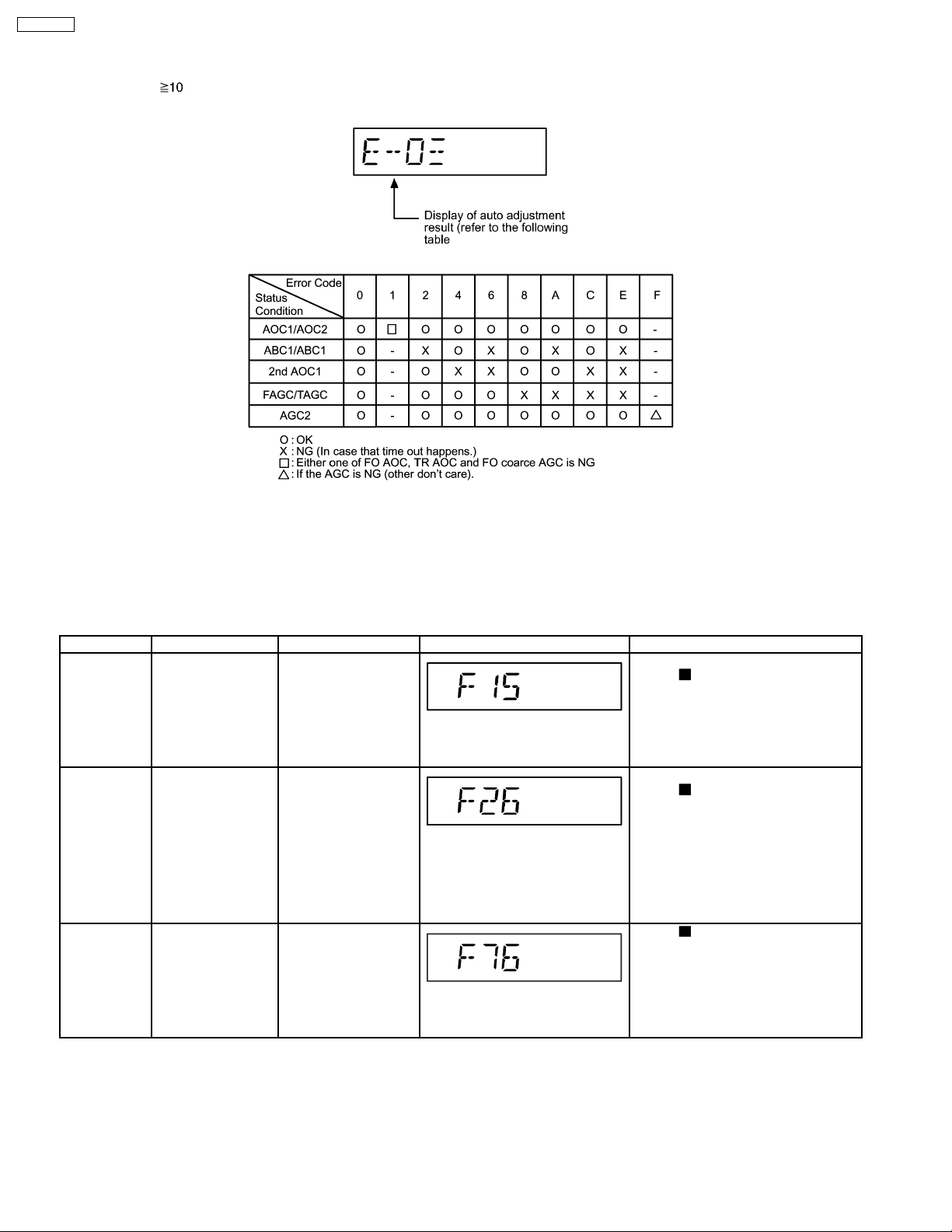
8.2.1. CD Self-Adjustment (AJST) Result Display
Purpose: To display result of self-adjustment for CD.
15
In doctor mode:
1. Press [
remote control.
To cancel, press [0] button remote
control.
To exit, press [
main unit or remote control.
In doctor mode:
1. Press [SLEEP] button on remote
control.
To exit, press [
fl
main unit or remote control.
], [1] & [4] button on
] button on
] button on
SC-EN33PC
Below is the procedures for this mode.
Step 1: Enter into Doctor mode (For more information refer to section 8.2 on key operation to enter into this mode).
Step 2: When [
], [1] & [4] are pressed at the doctor mode, the following shall be displayed for 3s. The result shall correspond
to the condition met as shown in the table below:
8.3. Error Code Table 1
8.3.1. Mechanism Error Code Table
Self-Diagnosis Function provides information on any problems occuring for the unit and its respective components by displaying
error codes. These error code such as U**, H** and F** are stored in memory and held unless it is cleared.
The error code is automatically display after entering into self-diagnostic mode.
Error Code Diagnosis Contents Description of error Automatic FL Display Remarks
F15 CD REST SW
abnormal
F26 Communication
between CD servo
LSI and micro-p
abnormal.
F76 Abnormality in the
output voltage of
stabilized power
supply.
CD traverse position
initial setting operation
failsafe counter
(1000ms) waiting for
REST SW to turn on.
Error no. shall be clear
by force or during cold
start.
CD function DTMS
command, after system
setting, if SENSE = “L”
cannot be detected.
Memory shall contain
F26code. After power
on, CD function shall
continue, error display
shall be “NO DISC”.
Error no. shall be clear
by force or cold start.
In normal operation
when “DCDET” is
detected “L” (IOIO) for
two consecutive times,
this error code will be
displayed for 2s & after
PCONT will be turned to
“L” (Low).
For CD unit.(For traverse).
Press [
For CD unit.(For traverse).
Press [
Press [ ] on main unit for next error.
] on main unit for next error.
] on main unit for next error.
16
SC-EN33PC
9 Assembling and Disassembling
9.1. Caution
“ATTENTION SERVICER”
Some chassis components may have sharp edges. Be careful when disassembling and servicing.
1. This section describes procedures for checking the operation of the major printed circuit boards and replacing the main
components.
2. For reassembly after operation checks or replacement, reverse the respective procedures.
Special reassembly procedures are described only when required.
3. Select items from the following index when checks or replacement are required.
4. Refer to the Parts No. on the page of “Parts Locatio n and Replacement Parts List” (Section 21), if necessary.
Warning :-
This product uses a laser diode. Refer to caution statement Precaution of Laser Diode.
Below is the list of disassembly sections
· Disasse mbly of Rear Cabinet
· Disasse mbly of Panel P.C.B. & LED P.C.B.
· Disasse mbly of Main P.C.B., Sensor P.C.B., Tuner P.C.B.
· Disasse mbly of Switch P.C.B. & Traverse Unit
· Disasse mbly of Power Switch P.C.B. & Tact Switch P.C.B.
· Replacement of Traverse Cover
· Disasse mbly of CD Servo P.C.B.
· Disasse mbly of Motor Unit & Motor P.C.B.
· Disasse mbly of CD Block & CD Lid
· Disasse mbly of Speakers
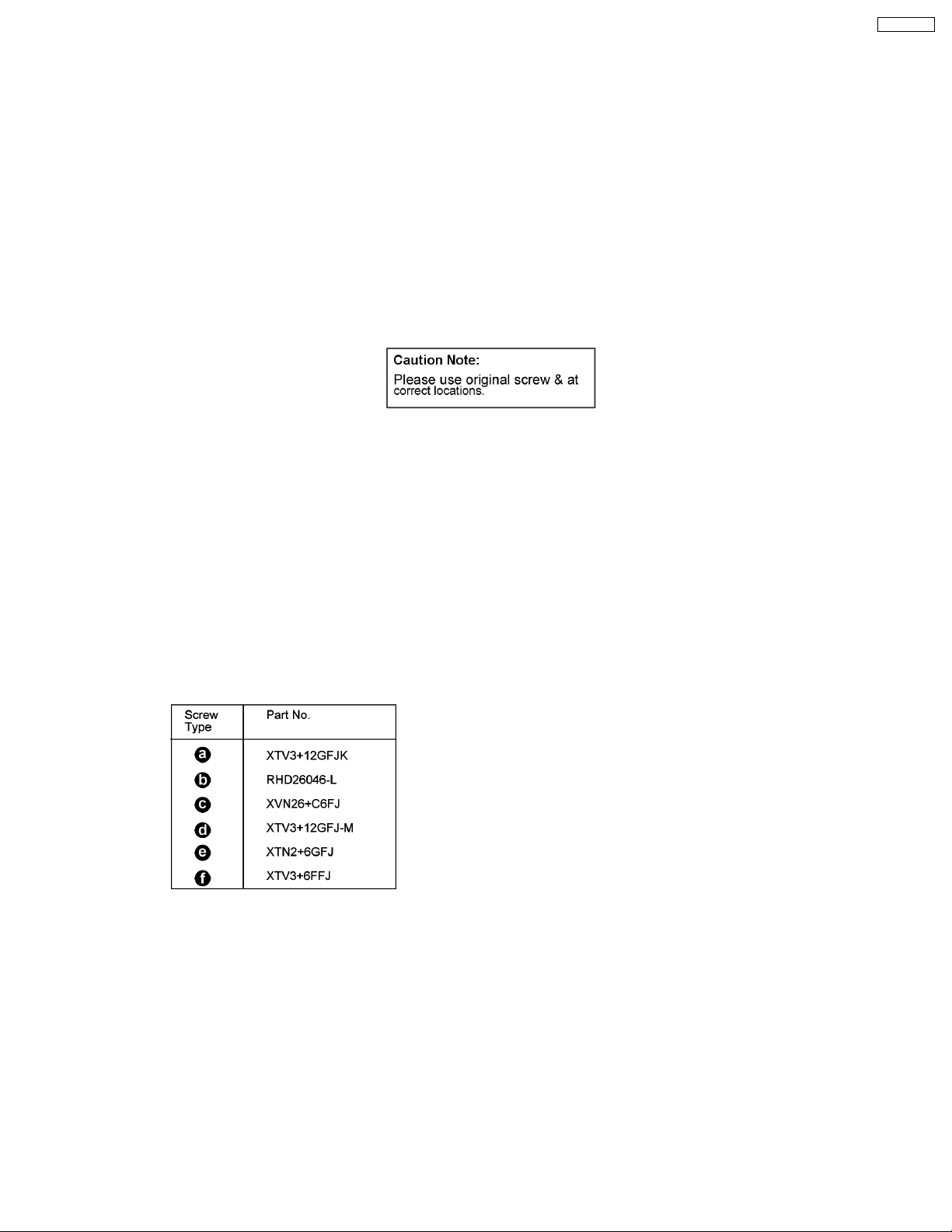
Below shown is part no. of different screws types used:
17
SC-EN33PC
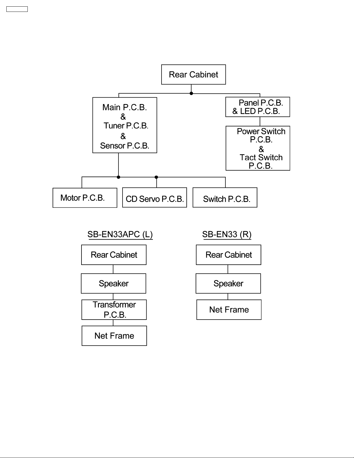
9.2. Disassembly flow chart
The following chart is the procedure for disassembling the casing and inside parts for internal inspection when carrying out the
servicing.
To assemble the unit, reverse the steps shown in the chart as below.
9.2.1. For Main unit
9.2.2. For Speaker unit
18
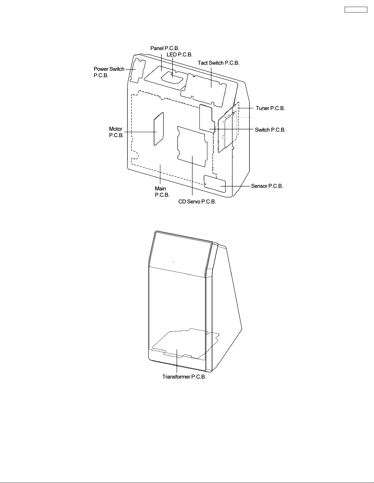
9.3. Main Components & P.C.B. Locations
9.3.1. Main Parts Locations
SC-EN33PC
9.3.2. Speaker Unit Parts Location (For SB-EN33A only)
19
SC-EN33PC
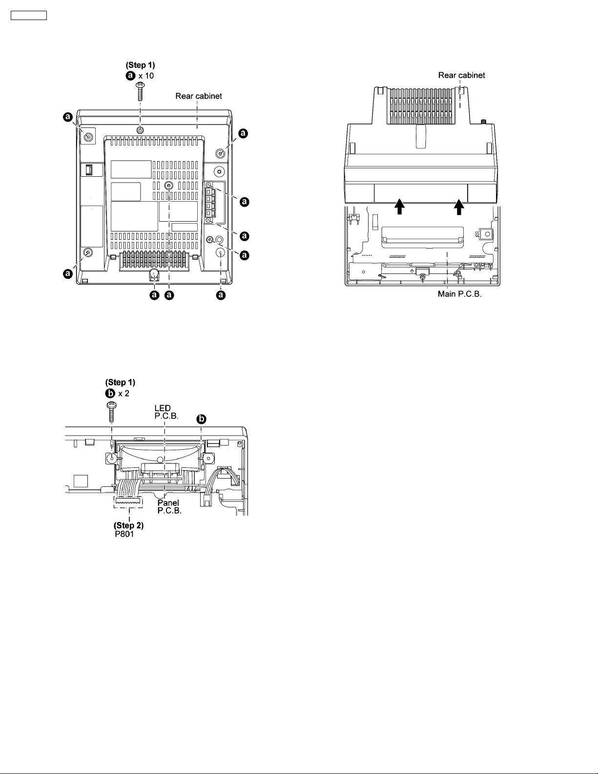
9.4. Disassembly of Rear Cabinet
Step 1 Remove 10 screws.
Step 2 Lift up the rear cabinet.
Step 3 Detach cable (FP806) on Main P.C.B. and remove the
rear cabinet as arrow shown.
9.5. Disassembly of Panel P.C.B. & LED P.C.B.
· Follow the (Step 1) - (Step 3) of Item 9.4 - Disassembly of Rear Cabinet
Step 1 Remove 2 screws on the LCD Holder unit.
Step 2 Detach cable (P801) on Main P.C.B..
9.6. Disassembly of Main P.C.B., Sensor P.C.B. & Tuner P.C.B.
· Follow the (Step 1) - (Step 3) of Item 9.4 - Disassembly of Rear Cabinet
Step 1 Remove 5 screws.
20
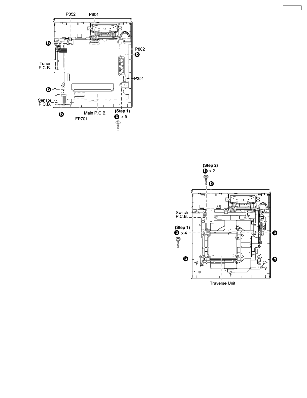
Step 2 Detach cables (P352, P351 ,FP701 ,P801 & P802) on
Main P.C.B..
Step 3 Lift up the Main P.C.B. Sensor P.C.B. and Tuner P.C.B.
9.7. Disassembly of Switch P.C.B. and Traverse Unit
· Follow the (Step 1) - (Step 3) of Item 9.4 - Disassembly of Rear Cabinet
· Follow the (Step 1) - (Step 3) of Item 9.6 - Disassembly of Main P.C.B., Sensor P.C.B. & Tuner P.C.B.
Step 1 Remove 4 screws.
Step 2 Remove 2 screws on Switch P.C.B..
SC-EN33PC
9.8. Disassembly of Power Switch P.C.B. & Tact Switch P.C.B.
· Follow the (Step 1) - (Step 3) of Item 9.4 - Disassembly of Rear Cabinet
· Follow the (Step 1) - (Step 2) of Item 9.5 - Disassembly of Panel P.C.B. & LED P.C.B.
Step 1 Detach cable (P802) on Main P.C.B..
Step 2 Remove 3 screws.
21
 Loading...