

Panasonic SA-HE70 User Manual
AV Control Receiver
Operating Instructions
Model No. SA-HE70
Dear customer
Thank you for purchasing this product.
Before connecting, operating or adjusting this product, please read
these instructions completely.
Please keep this manual for future reference.
RQT6193-P
P
AUDIO
Table of contents
IMPORTANT SAFETY INSTRUCTIONS ................................2
Supplied accessories
................................................................3
The remote control
....................................................................3
Troubleshooting guide
...........................................................16
Specifications
...........................................................................17
Maintenance
..............................................................................17
Warranty (U.S.A.)
.....................................................................18
Product Service
........................................................................18
Servicenter List (U.S.A.)
.........................................................19
Listening caution
....................................................Back cover
Equipment connections
6
Speaker connections
4
Settings
8
Step 1
Basic operations
10
Before use
Reference
PC
Step 1
Step 2
Step 3
Step 4
Before use
Others
Reference
Step 2
Step 3
Step 4
Control guide ............................................................................12
Presetting
...................................................................................14
Other settings
...........................................................................14
Making a recording
..................................................................15
Using outdoor antennas
........................................................15
Others
TOP MENU
DISPLAY
TV
EFFECT LEVEL
DISC
DECK 1/2
/
VIDEO
TV
VCR
DVD
TAPE CD
TUNER/BAND
DIRECT TUNING/
321
DISC ENTER
6
54
≥10/ENTER
9087
ENTER
//
/
SOUND MODE
SFC
CH
VOLUME
POWER
MENU
8
SUBWOOFER
SPEAKERS
+–
TEST
MUTING
+–
PHONES
- HELP
– RESET
wq
SFC MODE
- BAND
– FM MODE
MEMORY
DSP
DOLBY
SOUND MODE
PRO LOGIC 2
TUNING
PRESET
2
1
DOWN UP
VOLUME
INPUT SELECTOR
BASS/TREBLE
BALANCE L R
DIGITAL INPUT
DVD 6CH INPUTSUBWOOFERTAPE MONITOR
34

2
RQT6193
IMPORTANT SAFETY INSTRUCTIONS
Safety
1. Power source—Connect the unit to a power source of the type
described in these instructions or as marked on the unit.
2. Polarization—The unit is equipped with a polarized power plug
where one blade is wider than the other. This safety feature
ensures that the plug fits into your household AC outlet only one
way. If the plug doesn’t fit one way, try reversing it. If the plug
still doesn’t fit, contact an electrician to replace the obsolete
outlet. Do not attempt to defeat the safety purpose of the plug.
3. Power cord protection—Route the AC power supply cord so
that it will not be walked on or pinched by items placed on or
against it. Never take hold of the plug or cord with wet hands.
Always grasp the plug body firmly when connecting and
disconnecting it.
4. Overloading—When connecting the AC power supply cord, be
careful not to overload the household AC outlet, extension cord,
or outlet from any other device as this can result in fire or electric
shock.
5. Nonuse periods—Turn the unit off when it is not in use. Unplug
the unit from the household AC outlet if it is not to be used for a
long time. Unplug the unit during lightning storms.
6. Attachments and accessories—Use only the attachments and
accessories recommended in these operating instructions.
Read these operating instructions carefully before using the unit. Follow the safety instructions on the unit and the safety precautions listed
below. Keep these operating instructions handy for future reference.
Installation
4. Outdoor antenna grounding—If you connect an outdoor
antenna, ground the antenna system to protect against voltage
surges and built-up static charges. Section 810 of the National
Electrical Code, ANSI/NFPA No. 70-1990, provides information
about grounding of the mast and supporting structure, grounding
of the lead-in wire to an antenna discharge unit, size of
grounding conductors, location of antenna-discharge unit,
connection to grounding electrodes, and requirements for the
grounding electrode. Refer to this diagram.
Environment
ELECTRIC
SERVICE
EQUIPMENT
GROUND
CLAMP
ANTENNA
LEAD IN
WIRE
ANTENNA
DISCHARGE UNIT
(NEC SECTION 810-20)
GROUNDING CONDUCTORS
(NEC SECTION 810-21)
GROUND CLAMPS
POWER SERVICE GROUNDING
ELECTRODE SYSTEM
(NEC ART 250, PART H)
NEC—NATIONAL ELECTRICAL CODE
1. Water and moisture—Do not use the unit near water, such as
near a bathtub or swimming pool. Avoid damp basements.
2. Heat—Situate the unit away from heat sources, such as
radiators.
Do not situate where temperatures fall below 5°C (41°F) or rise
above 35°C (95°F).
3. Power lines—Take care when setting up an outdoor antenna
that it is not near overhead power lines, electric lights, or
electrical circuits, and that there is no danger of the antenna
falling on power lines, electric lights, or electrical circuits. When
installing an outdoor antenna, take extreme care not to touch
such power lines or circuits, as contact with them can be fatal.
Placement
1. Ventilation—Situate the unit so that it receives proper
ventilation. Do not install in a confined space such as a
bookcase or cabinet. Allow at least 10 cm (4 inches) clearance
from the rear of the unit. To prevent the risk of electric shock or
fire due to overheating ensure curtains and other materials do
not obstruct the unit’s ventilation.
2. Foreign material—Ensure objects and liquids do not get into
the unit. Avoid exposing the unit to excessive smoke, dust,
mechanical vibration, and shock.
3. Magnetism—Situate the unit away from equipment and devices
that generate strong magnetic fields.
4. Stacking—Do not place heavy objects on top of this unit.
5. Surface—Place the unit on a flat, level surface.
6. Carts and stands—Use the unit only with carts
and stands recommended by the manufacturer.
Move carts with care. Sudden stops, excessive
force, and uneven surfaces can cause carts to
overturn.
7. Wall and ceiling mounting—Do not mount the unit on walls or
ceilings unless specified in the instructions.
Maintenance
(See page 17 for details.)
Unplug the unit from the household AC outlet before cleaning.
Clean with a damp cloth.
Do not use abrasive pads, scouring powders, or solvents.
Service
1. Damage requiring service—The unit should be serviced by
qualified service personnel if:
(a) The AC power supply cord or the plug has been damaged; or
(b) Objects or liquids have gotten into the unit; or
(c) The unit has been exposed to rain; or
(d) The unit does not operate normally or exhibits a marked
change in performance; or
(e) The unit has been dropped or the cabinet damaged.
2. Servicing—Do not attempt to service the unit beyond that
described in these operating instructions. Refer all other
servicing to authorized servicing personnel.
3. Replacement parts—When parts need replacing ensure the
servicer uses parts specified by the manufacturer or parts that
have the same characteristics as the original parts.
Unauthorized substitutes may result in fire, electric shock, or
other hazards.
4. Safety check—After repairs or service, ask the servicer to
perform safety checks to confirm that the unit is in proper
working condition.
3
RQT6193
Please check and identify
the supplied accessories.
1 AC power supply cord
(RJA0065-A)
1 AM loop antenna set
(RSA0012)
(AM loop antenna,
antenna holder, screw)
Use the numbers indicated in parentheses when asking for
replacement parts.
1 FM indoor antenna
(RSA0006-L)
2 Batteries
1 Remote control
(EUR7702KE0)
Step 1
Step 2
Step 3
Step 4
Before use
Others
WARNING:
TO REDUCE THE RISK OF FIRE, ELECTRIC
SHOCK OR PRODUCT DAMAGE, DO NOT
EXPOSE THIS APPARATUS TO RAIN,
MOISTURE, DRIPPING OR SPLASHING AND
THAT NO OBJECTS FILLED WITH LIQUIDS,
SUCH AS VASES, SHALL BE PLACED ON THE
APPARATUS.
Reference
CAUTION
Do not place anything on top of this unit or block the heat
radiation vents in any way. In particular, do not place tape decks
or CD/DVD players on this unit as heat radiated from it can
damage your software.
The lightning flash with arrowhead symbol, within
an equilateral triangle, is intended to alert the user
to the presence of uninsulated “dangerous voltage”
within the product's enclosure that may be of sufficient magnitude to constitute a risk of electric shock
to persons.
The exclamation point within an equilateral triangle
is intended to alert the user to the presence of
important operating and maintenance (servicing)
instructions in the literature accompanying the appliance.
CAUTION:TO REDUCE THE RISK OF ELECTRIC
SHOCK, DO NOT REMOVE SCREWS.
NO USER-SERVICEABLE PARTS
INSIDE.
REFER SERVICING TO QUALIFIED
SERVICE PERSONNEL.
CAUTION
RISK OF ELECTRIC SHOCK
DO NOT OPEN
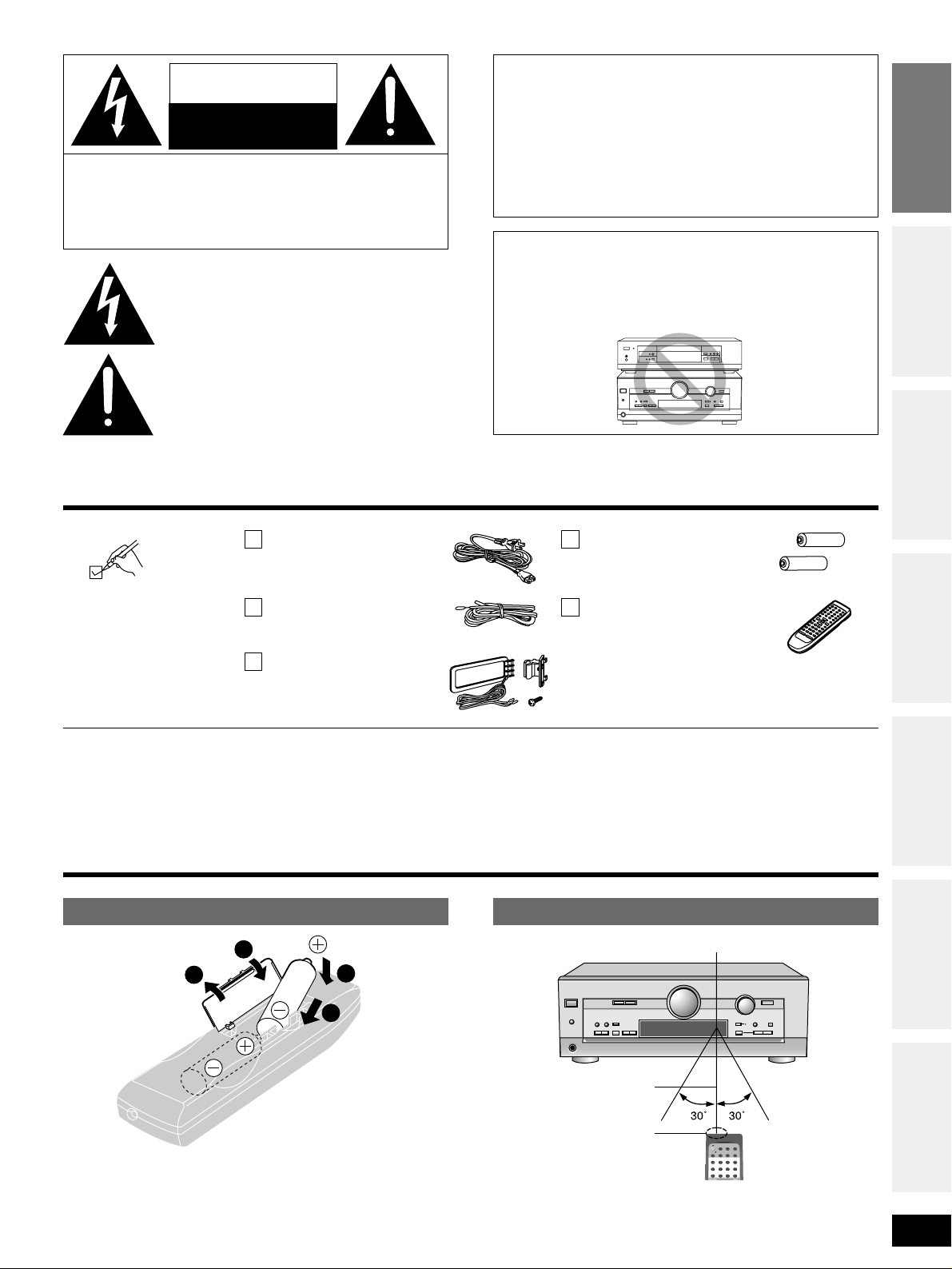
(R6, AA, UM-3)
Batteries
¡Insert so the poles (+ and –) match those in the remote control.
¡Do not use rechargeable type batteries.
¡Keep the transmission window and the unit’s sensor free from
dust.
¡Operation can be affected by strong light sources, such as direct
sunlight, and the glass doors on cabinets.
POWER
SPEAKERS
SFC MODE
DOWN UP
VOLUME
INPUT SELECTOR
DVD 6CH INPUTSUBWOOFERTAPE MONITOR
BASS/TREBLE
34
BALANCE L R
DIGITAL INPUT
PHONES
- HELP
– RESET
- BAND
– FM MODE
MEMORY
TUNING
PRESET
DSP
SOUND MODE
DOLBY
PRO LOGIC 2
8
2wq1
TV
TUNER/BAND
VCR
TAPE CD
DVD
AUDIO
321
6
≥10/ENTER
54
9087
DIRECT TUNING/
DISC ENTER
Remote control signal sensor
Transmission window
Use
The remote control
7 meters (23 feet)
Supplied accessories
Refer to the separate booklet, “Remote Control
Operation Guide”, for remote control operation
details.
(Only for U.S.A.)
To order accessories contact 1-800-332-5368 or web site
(http://www.panasonic.com).
4
1
3
2
L
R
L
R
LOOP ANT
HOLDER
FM
ANT
AM
ANT
GND
LOOP
EXT
75Ω
DIGITAL IN
TAPE
S-VIDEO
TV
OPTICAL1
(TV)
REC
(OUT)
PLAY
(IN)
OPTICAL2
(DVD)
MONITOR
OUT
TV
CD
MONITOR
OUT
CENTER
SUR
RO
UND
SUBWOOFER
L
R
TV
IN
VCR
VCR
DVD/DVD 6CH
SPEAKERS
HAUT-PARLEURS
AC IN
∼
AC
OUTLET
SUBWOOFER
IN
IN
IN
IN
IN
FRONT
OUT
OUT
DVD
IN
COAXIAL
SURROUND
FRONT
CENTER
6-8Ω
6-8Ω
6-8Ω
EACH SPEAKER
CHAQUE
EACH SPEAKER
CHAQUE
R L
R L
TV
4
RQT6193
Speaker connections
Step
1
2 3 4
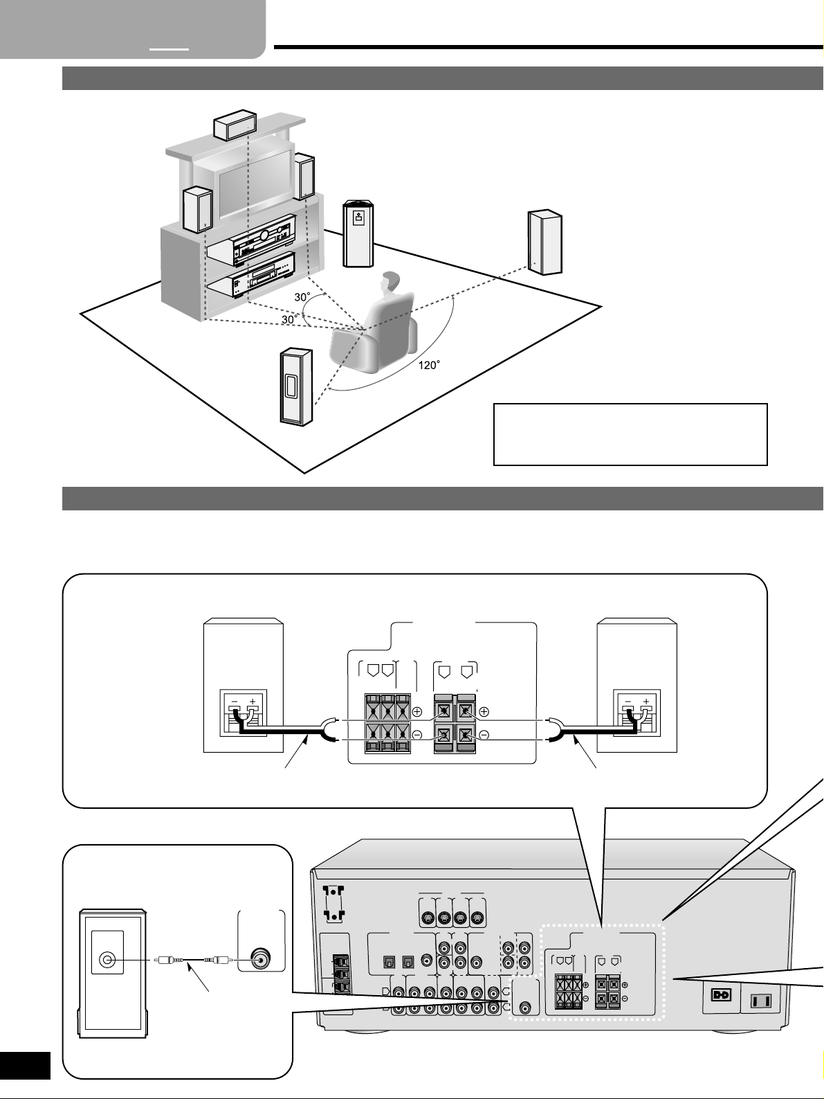
Placement of speakers
Connecting speakers
Other connections are possible depending on your speaker system.
See your speaker system’s operating instructions for details.
The front, center, and surround speakers should be
placed at approximately the same distance from the
seating area. The angles in the diagram are
approximate.
A
B
C
D
E
F
Active subwoofer
Monaural connection cable
SPEAKERS
HAUT-PARLEURS
SURROUND
FRONT
CENTER
6-8Ω
6-8Ω
6-8Ω
EACH SPEAKER
CHAQUE
EACH SPEAKER
CHAQUE
R L
R L
SUBWOOFER
OUT
INPUT
F
Subwoofer
Front speakers – Impedance: 6–8 Ω
AB
Right Left
Speaker cableSpeaker cable
Turn off the receiver before connecting the speakers.
5
RQT6193
Peripheral equipment and cables sold separately unless otherwise indicated.
Front speakers (A left B right)
Place on the left and right of the TV at seated ear height so that
there is good coherency between the picture and sound.
Center speaker (C)
Place underneath or above the center of the TV. Aim the speaker at
the seating area.
Surround speakers (D left E right)
Place slightly behind the seating area, about one meter (3 feet)
higher than ear level.
Subwoofer (F)
The subwoofer can be placed in any position as long as it is at a
reasonable distance from the TV.
Note that some experimentation can yield the smoothest low
frequency performance. Placement near a corner can increase the
apparent output level, but can result in unnatural bass.
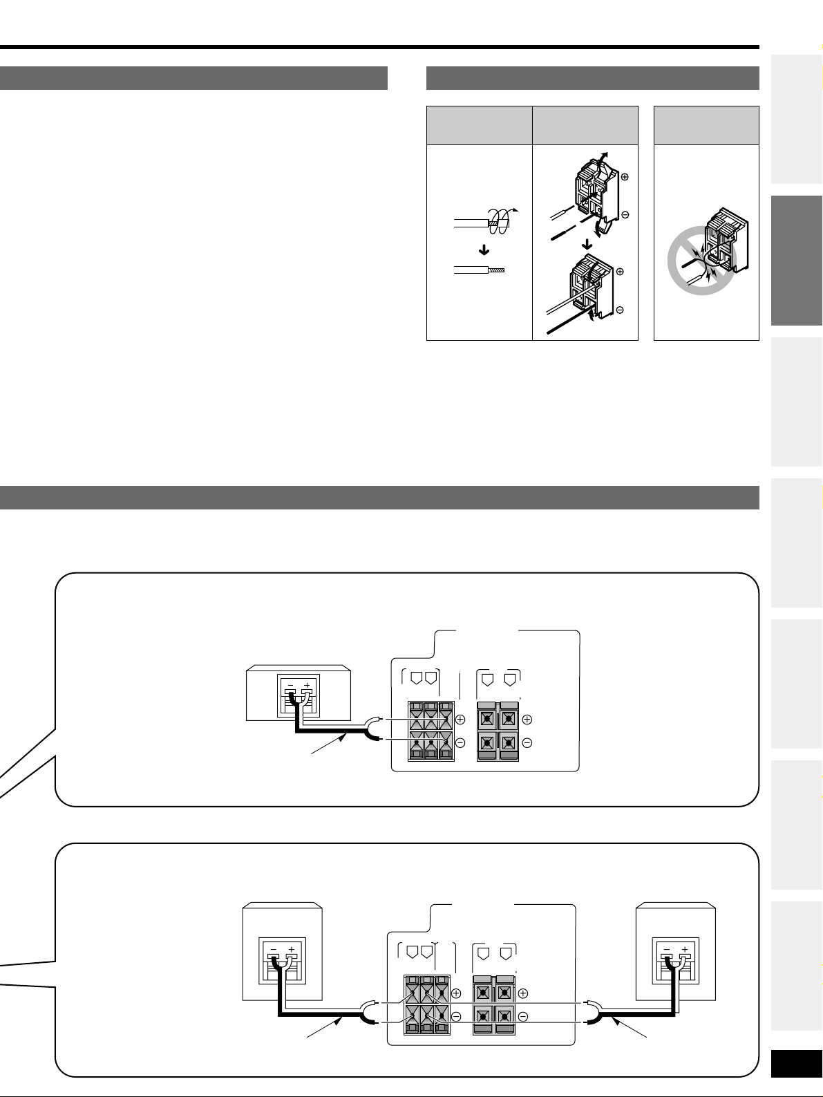
Cable Speaker terminals Note
Speaker cable
Step 1
Step 2
Step 3
Step 4
Before use
Others
Reference
D
Do not short
circuit.
Speaker cable
Twist the wire
SPEAKERS
HAUT-PARLEURS
SURROUND
FRONT
CENTER
6-8Ω
6-8Ω
6-8Ω
EACH SPEAKER
CHAQUE
EACH SPEAKER
CHAQUE
R L
R L
SPEAKERS
HAUT-PARLEURS
SURROUND
FRONT
CENTER
6-8Ω
6-8Ω
6-8Ω
EACH SPEAKER
CHAQUE
EACH SPEAKER
CHAQUE
R L
R L
Center speaker – Impedance: 6–8 Ω
C
Surround speakers – Impedance: 6–8 Ω
Right Left
ED
Speaker cable
Speaker cable
L
R
L
R
LOOP ANT
HOLDER
FM
ANT
AM
ANT
GND
LOOP
EXT
75Ω
DIGITAL IN
TAPE
S-VIDEO
TV
OPTICAL1
(TV)
REC
(OUT)
PLAY
(IN)
OPTICAL2
(DVD)
MONITOR
OUT
TV
CD
MONITOR
OUT
CENTER
SURROUND
SUBWOOFER
L
R
TV
IN
VCR
VCR
DVD/DVD 6CH
SPEAKERS
HAUT-PARLEURS
AC IN
∼
AC
OUTLET
SUBWOOFER
IN
IN
IN
IN
IN
FRONT
OUT
OUT
DVD
IN
COAXIAL
SURROUND
FRONT
CENTER
6-8Ω
6-8Ω
6-8Ω
EACH SPEAKER
CHAQUE
EACH SPEAKER
CHAQUE
R L
R L
TV
6
RQT6193
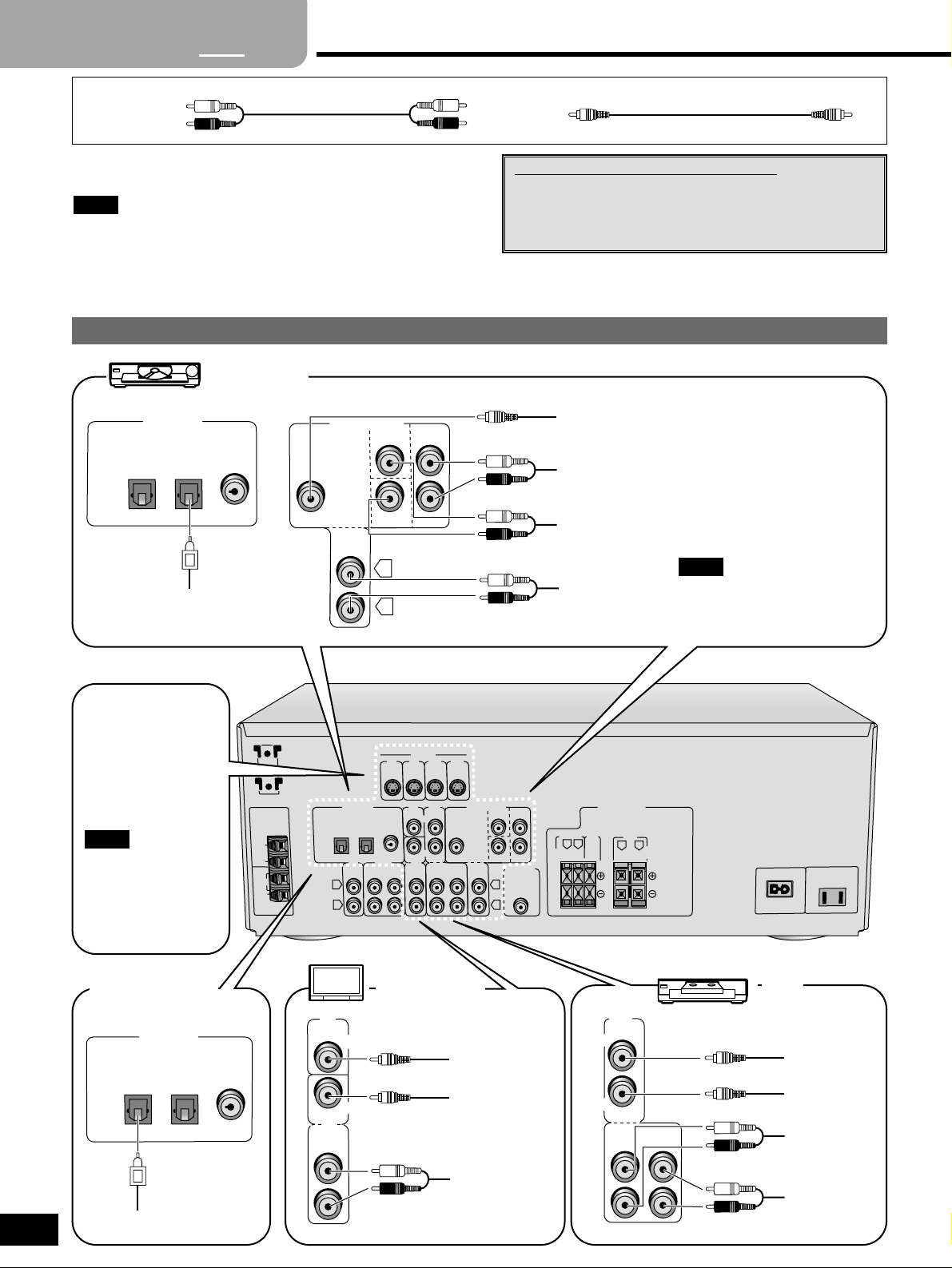
Equipment connections
TV, VCR and DVD player
Stereo connection cable
White (L)
Red (R)
Video connection cable
Changing the digital input settings
You can change the input settings for the digital
terminals if necessary. Note the equipment you have
connected to the terminals, then change the settings (
\
pages 8 and 9).
Step
1
2
3 4
L
R
CENTER
SURROUND
SUBWOOFER
L
R
DVD/DVD 6CH
IN
IN
FRONT
DVD player
VIDEO OUT
AUDIO OUT
(SURROUND L, R)
AUDIO OUT
(CENTER, SUBWOOFER)
AUDIO OUT
(FRONT L, R)
VCR
OUT
VCR
IN
IN
OUT
VIDEO IN
VIDEO OUT
AUDIO IN
AUDIO OUT
TV or monitor
VIDEO IN
VIDEO OUT
AUDIO OUT
TV
MONITOR
OUT
IN
TV
Connect to FRONT L, R if your
DVD player does not have 6
channel output.
Note
DIGITAL IN
OPTICAL1
(TV)
OPTICAL2
(DVD)
COAXIAL
DIGITAL AUDIO OUT
To connect equipment, refer to the appropriate operating
instructions.
¡Do not bend the optical fiber cable.
¡Turn off all components before making any connections.
¡Use digital connection to enjoy Dolby Digital or DTS (\page 10).
¡Use analog connection to enjoy sources that cannot be decoded
on this unit and to record a source (\pages 10 and 15).
Note
The S-VIDEO
terminals
Connections through
these terminals provide
higher quality pictures
than through the video
terminal.
Video signals input into
the VIDEO terminals
cannot be output from
S-VIDEO terminals or
vice versa.
Note
Satellite receiver
etc.
DIGITAL IN
OPTICAL1
(TV)
OPTICAL2
(DVD)
COAXIAL
DIGITAL OUT
 Loading...