

Page 1
Manufactured by:
81-IN3043-9922
Before attempting to connect or operate this product, please read these instructions completely.
for
MODEL: Indoor Wall / Corner Housings
PIH800
NOTE: Max. storage space is 8"
(Panasonic 1/3" Camera Class
with Panasonic Fixed Focal Lens Series)
Indoor Plastic Camera Housing - PIH800
General Instructions:
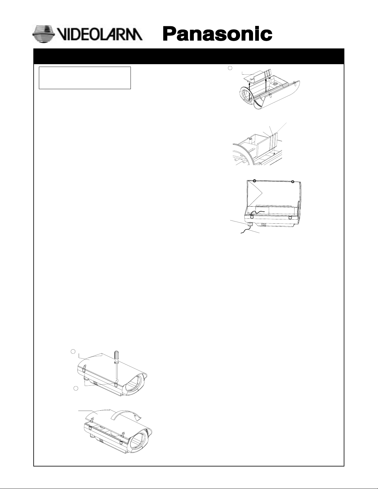
1. Carefully remove all equipment from the box.
2. Using a phillips head screw driver, loosen the (2) two phillips
head screws (F). The screws are captive, so they will not release
from the PIH800 Housing (A) (See Fig. 1).
3. Next, open the PIH800 Housing lid, (lid opens from the side of the
screws (See Fig. 2).
4. Carefully lift camera sled (B) out of housing as shown in Fig. 3.
5. Using the 1/4-20 screw (H) on the camera sled, attach a camera
with a maximum camera length of (8) eight inches to the sled. For
smaller cameras, use the first slot on the sled to lock the camera
and sled in place (See Fig. 4). Be sure that the end of the camera
lens does not exceed the camera sled by more than a 1/2". For
medium size cameras, use the second slot on the sled to lock the
camera and sled in place (Fig. 4). Be sure that the end of the
camera lens does not exceed the camera sled by more than 1". For
larger cameras, use the third slot on the sled to lock the camera and
sled in place (Fig. 4). Be sure that the end of the camera lens does
not exceed the camera sled by more than 1 1/2". The camera can
be adjusted forward and back using the slot in the sled, if necessary.
6. Install the liquid-tight connector (C) so the nut is on the inside of
the housing. Be sure to tighten the inside nut firmly against the
flat surface. Next, loosen the outside nut and feed the cable
through the connector leaving enough cable to reach the camera.
Tighten the outside nut of the liquid-tight connector and complete
all electrical connections (See Fig. 5). Use 24 VAC Class 2 Power
Supply only.
7. Make all final camera adjustments, and close lid of housing.
Tighten the (2) two phillips screws. (Note: Camera tray will not be
fully secure until lid is tightened with screws).
A
PIH800 Housing
Fig. 1
Fig. 2
F
Phillips Head
Screws
PIH800
Housing lid
PRODUCT INSTRUCTIONS
B Camera sled
Fig. 3
Slot #2
(medium cameras)
Slot #3 (large cameras)
Fig. 4
Liquid-tight
connectors
Fig. 5
NOTE: To wall mount the PIH800 housing:
A. Place the wall mount bracket against a flat surface in the desired
location. Mark the location using the (3) three mounting holes (See
Fig. 1A).
B. Remove the bracket and drill a cable access hole approximately
in the center of the (3) three marked mounting holes (See Fig. 1A).
C. Next, run the cable from the wall through the cable access hole
on the bracket body (See Fig. 1A). Using the (3) three marks from
the previous step, mount the bracket to the surface using appropriate fasteners.
D. Be sure the bracket is firmly affixed to the surface and install the
(3) three hole covers provided in the packet (See Fig. 2A).
E. Fasten the tilt mount (M) to the PIH800 housing body using two
1/4-20 screws (Q) on the tilt mount (See Fig. 3A).
F. Attach the tilt mount and PIH800 housing to the pan mount (N)
and tighten the tilt knob (O) (See Fig. 4A). Loosen the liquid-tight
connector (C) and feed the cable through the connector leaving
enough cable to reach the camera. Tighten the liquid-tight connector and complete all electrical connections (See Fig. 5A). Use
24 VAC Class 2 Power Supply only.
G. Make all final camera adjustments, and close lid of housing.
Tighten the (2) two phillips screws.
H. Adjust the pan/tilt capabilities of the bracket with the (2) two
knobs, one for panning (N) and one for tilting (M) (See Fig. 6A).
Tighten both knobs when desired viewing angle is achieved.
Note: The pan knob has a screw length of 1/2" and the tilt knob
has a length of 5/16".
Slot #1 (smaller cameras)
Electrical cable
Page 2
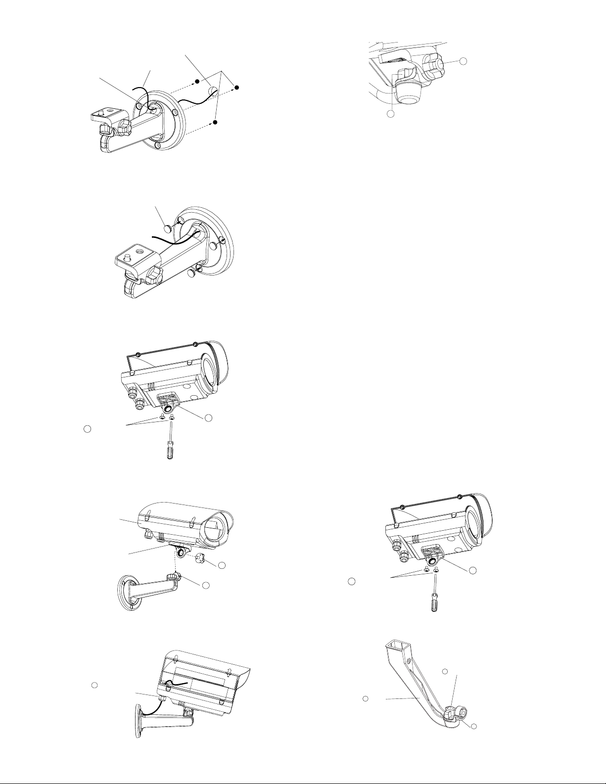
Cable access hole
Access hole in wall
Cable
Marked mounting
holes
P Tilt knob
Fig. 1A
Fig. 2A
Fig. 3A
Q 1/4-20 Screws
Hole covers
M Tilt mount
Fig. 6A
Q Pan knob
Note: (1) Follow these instructions for ceiling mounting the Indoor
Plastic Camera Housing (PIH800) using the optional PJM8. (2) When
using the PJM8 to ceiling mount the PIH800, the panning capabilities of
PJM8 are limited to 5° left or right. You must aim the bracket towards
viewing area prior to mounting the PUM8:
L. Carefully remove all equipment from box.
M. Follow steps 1-5 for PIH800 set-up.
N. Follow steps A-D for PUM8 set-up.
O. Attach the tilt mount (M) to the PIH800 using the (2) two 1/4-20
screws as shown in Fig. 1B.
P. Attach the pan mount (N) to the PUM8 (S) using the pan knob (P) and
tighten (See Fig. 2B).
Q. Connect the PJM8 to the PUM8 as shown in (Fig.3B), using the (2)
two 10-24 screws (T) provided. Be sure that the front cover (L) is not
attached to the PUM8 bracket.
R. Attach the tilt mount and PIH800 to the pan mount (N) and tighten the
tilt knob (O) (Fig.4B). Be sure that the pan mount faces away from the
PJM8 bracket as shown in Fig. 2B, so that the lid of the PIH800
housing will open easily. Loosen the liquid-tight connector ( C) and
feed the cable through the connector leaving enough cable to reach
the camera. Tighten the liquid-tight connector and complete all
electrical connections (See Fig.5B).
S. Make all final camera adjustments, and close lid of housing. Tighten
the (2) two phillips screws.
T. Adjust the pan/tilt capabilities of the bracket with the (2) two knobs,
one for panning (N) and one for tilting (O) (Fig. 6B). Tighten both
knobs when desired viewing angle is achieved.
Fig. 4A
Fig. 5A
PIH800
Tilt mount
C
Liquid-tight
connector
O Tilt knob
P Pan mount
- 2 -
Fig. 1B
Fig. 2B
M Tilt mount
Q 1/4-20 Screws
P Pan adjustment knob
S PJM8
N Pan mount
Page 3

B
G
Fig. 3B
Fig. 4B
J PUM8
S PJM8
S PJM8
M Tilt mount
P Pan knob
T 10-24 Screws
A PIH800
O Tilt knob
N Pan mount
H
I
A
C
D
Q
R
M
O
J
J
K
E
P
N
L
F
T
S
Fig. 5B
Fig. 6B
P Pan knob
C Liquid-tight
connector
O Tilt knob
Description Qty.
A PIH800 Housing Body 1
B Camera Sled 1
C Liquid-Tight Connector 2
D Window 1
E Plugs 2
F 8-32x5/16 Phillips Head Screws 2
G 8-32 O-rings 2
H 1/4-20x3/8" Screw 1
I 1/4-20 O-ring 1
J PUM8 Bracket Body 1
K Hole Covers 3
L Front Cover 1
M Tilt Mount 1
N Pan Mount 1
O Tilt Adjustment Knob 1
P Pan Adjustment Knob 1
Q 1/4-20x3/8" Screw 2
R O-ring 2
S PJM8 1
T 10-24 x 1/2" Phillips Screws 2
- 3 -
Page 4

1. Read Instructions - All the safety and operating instructions
!
should be read before the unit is operated.
2. Retain Instructions - The safety and operating instructions
should be retained for future reference.
3. Heed Warnings - All warnings on the unit and in the operating
instructions should be adhered to.
4. Follow Instructions - All operating and user instructions should
be followed.
5. Electrical Connections - Only a qualified electrician should
make electrical connections.
6. Attachments - Do not use attachments not recommended by the
product manufacturer as they may cause hazards.
7. Cable Runs - All cable runs must be within permissible distance.
8. Mounting - This unit must be properly and securely mounted to
a supporting structure capable of sustaining the weight of the
unit. Accordingly:
a. The installation should be made by a qualified service person
and should conform to all local codes.
b. Care should be exercised to select suitable hardware to install
the unit, taking into account both the composition of the
mounting surface and the weight of the unit. Be sure to
periodically examine the unit and the supporting structure to
make sure that the integrity of the installation is intact. Failure
to comply with the foregoing could result in the unit separating
from the support structure and falling, with resultant damages
or injury to anyone or anything struck by the falling unit.
SAFETY PRECAUTIONSIMPORTANT SAFEGUARDS
CAUTION
RISK OF
ELECTRIC SHOCK!
CAUTION: TO REDUCE THE RISK OF
ELECTRICAL SHOCK, DO NOT EXPOSE
COMPONENTS TO WATER OR MOISTURE.
The lightning flash with an arrowhead symbol,
within an equilateral triangle, is intended to alert
the user to the presence of non-insulated
"dangerous voltage" within the product's enclosure
that may be of sufficient magnitude to constitute
a risk of electric shock to persons.
The exclamation point within an equilateral triangle
is intended to alert the user to presence of
!
UNPACKING
Unpack carefully. Electronic components can be damaged if
improperly handled or dropped. If an item appears to have been
damaged in shipment, replace it properly in its carton and notify
the shipper.
important operating and maintenance (servicing)
instructions in the literature accompanying the
appliance.
Be sure to save:
1. The shipping carton and packaging material. They are the safest
material in which to make future shipments of the equipment.
2. These Installation and Operating Instructions.
SERVICE
For service on Panasonic/Videolarm equipment contact:
Panasonic Technical Center
54 West Gude Dr.
Rockville MD 20850-1150
Phone: 301-762-5125
Fax: 301-251-0347
PANASONIC TECHNICAL SUPPORT
1-800-528-6747
9:00 AM - 5:00 PM EASTERN TIME
- 4 -
 Loading...