

Page 1

PFW850 Workstation
Software Version 0.X
for use with a WJ-SX850 Surveillance Control System
Installation & User Manual
Document Version 0.1
for System Administrators installing and configuring
PFW850 Workstation Software
and day-to-day use by Security Specialists
Panasonic
Panasonic®
PanasonicPanasonic
Matsushita Electric Corporation of America
MECA Technology Development Center
Systems Development Division — Technical Services Department
Secaucus, New Jersey 07094
PFW850 Workstation 082399PFW850WS109276
®
®®
Page 2

Page 3

Panasonic
MECA TDC
C
ONTENTS
ELCOME
W
INTRODUCTION......................................7
DOCUMENT CONVENTION....................8
7
ONTENTS
C
HAT AND
W
WHAT THIS SYSTEM DOES ................11
HOW IT WORKS ...................................11
The Map .............................................12
Interactive Response..........................12
Alarms .....................................................12
Cameras...................................................12
Presets and Sequences ............................13
Executing Macros...............................13
Voice Commands ...............................13
Text-to-Speech.........................................13
Voice Recognition ...................................13
INSTALLATION.....................................14
NSTALL
I
PREREQUISITES..................................15
PLATFORM...........................................15
FROM CD-ROM.....................................17
FROM DISKETTES................................26
15
SCS Database....................................15
Setup Utility ........................................15
Hardware............................................15
Optional...................................................16
Operating System...............................16
Recommended Settings .....................16
Stand-Alone Installation......................18
Server Installation...............................21
OW
H
? 11
PFW850 Workstation
TART
S
DATABASE RETRIEVAL......................28
LOGIN....................................................29
PERATION
O
THE MAP...............................................30
THE KEYPAD........................................31
MAIN MENU ..........................................32
UP 28
At Startup............................................28
During Operation ................................28
30
Alarm Control......................................32
3 C
ONTENTS
Page 4

Alarm States ............................................33
Select Actions ..........................................34
Control Actions .......................................36
Alarm Output ......................................36
Area Select.........................................37
Camera...............................................38
Select Actions ..........................................38
Control Actions .......................................39
Camera Control Settings.........................41
Camera Preset ...................................43
Select Actions ..........................................44
Control Actions .......................................44
Group Preset......................................44
Select Actions ..........................................45
Group Sequence ................................46
Select Actions ..........................................46
Joystick Settings.................................47
Login/Logout.......................................48
Operator Login........................................48
Operator Logout......................................48
Monitor................................................49
Select Actions ..........................................49
Control Actions .......................................51
Recorder.............................................52
Select Actions ..........................................52
Control Actions .......................................53
Speech Settings .................................55
Text-to-Speech.........................................55
Speech Recognition .................................56
Tour Sequence...................................59
Select Actions ..........................................59
Control Actions .......................................60
Video Capture.....................................62
Actions.....................................................62
Video Settings ....................................64
Configure.................................................64
Image Control .........................................64
CURRENT STATE.................................65
ASSIST MODE ......................................66
STATUS TABS......................................67
System Status ....................................67
Macro Status ......................................68
Video Loss..........................................68
Active Alarms......................................69
Timed Macros.....................................69
Readiness Level.................................70
About..................................................71
MACRO EXECUTION............................72
OYSTICK
J
Component Selection .........................74
Camera Control..................................75
YSTEM
S
GENERAL..............................................78
OPERATOR INTERACTION .................79
FILE TRANSFER...................................82
(E
ESSAGES
M
XTERNAL
77
4
) 73
Page 5

Panasonic
MECA TDC
LOSSARY
G
ACRONYMS..........................................85
TERMS...................................................86
NDEX
I
91
85
ONTENTS
C
PFW850 Workstation
5 C
ONTENTS
Page 6

6
Page 7

Panasonic
MECA TDC
ELCOME
W
W
INTRODUCTION
Welcome to the PFW850 Workstation application. This guide is
organized with a focus on use. In other words, this document is
created not in alphabetical order, but in a logical manner. First, an
explanation of what, how you would use this application. You will be
required to Install the Software, get databases, and operate the
workstation.
In addition, the following sections will describe how to use this
controller in order to manipulate the video, use the maps, and control
components.
ELCOME
!
Install: detailed procedures for installing this application
via CD-ROM and floppy diskette.
!
Start Up: describes steps that occur each time the
application is started.
!
Operation: detailed description of all aspects of the
application including component manipulation, setup, and
information.
!
Joystick (External): description of the buttons that
appear on the supported external joystick and actions that
can be performed.
!
System Messages: description of message that occur as a
result of the system malfunction, operator interaction or
file transfer. This section will describe each message and
what the operator should do as a result.
!
Glossary: describes acronyms and terms used that may
not be commonly known to the administrator or operator.
PFW850 Workstation
7 W
ELCOME
Page 8

DOCUMENT CONVENTION
This guide uses the following conventions when describing the use
and operation of this product.
♦
Menu options, field names and text that you must enter in
a dialog box or window appear in
♦
If a word stands for something else, it appears in italics, as
in the following example:
Drive:\directory\filename.ext
You would enter the actual drive, directory and file name rather than
the words drive, directory and filename.ext.
♦
Keys with name consisting of more than one character
appear within brackets, as in
the brackets; simply press the indicated key.
this type style
[Alt]
, or
[Enter].
.
Do not type
♦
When you see
guide, press and hold down the
[Alt]
key, or
[Shift]
key or
[Alt], [Shift],
[Ctrl]
or
Key in this
[Ctrl]
while you press the specified key. Then release both
keys. For example, to enter
[Ctrl]
A, press the
[Ctrl]
and enter the letter “A” key simultaneously.
♦
Some keyboards have a
[Enter]
♦
Function Keys are the “F” keys along the top of your
key. This guide uses
[Return]
[Enter]
key rather than an
to indicate both.
keyboard. This document refers to Function Keys by
putting brackets around the key such as
[F1]
for the “F1”
key.
♦
File name references appear in all capitals letters, as the
“The file name is
SETUP.EXE
.” However, if a file name
is part of a procedure, it appears in all lower case letters as
in “ At the Windows command line, type
[Enter].
press
♦
Within the windows environment, there are often several
Setup.exe
ways to select an option. For example, to select OK, you
can do any of the following:
!
Click on OK with the mouse.
key
key
and
!
!
Press
Press
[Alt]
O
[Enter]
8
Page 9

Panasonic
MECA TDC
ELCOME
W
♦
This document uses the terms select, type or enter to
indicate any of these actions and can be performed using
several instruments such as:
!
PC keyboard
!
Mouse
!
External joystick
♦
The term “Drag” in this document refers to the process of
clicking and holding down the left mouse button while
moving the mouse pointer on screen. The term “Drop”
means to release the mouse button at the completion of
this process.
This Document also uses unique text formatting to describe various
features, capabilities, or problems, described below:
This box will refer you to a different section with systematic instructions for
filling out specific data. Such as, repetitive instructions for some sections or
steps are explained in only one section.
Note: Text with this appearance is a special instruction, rule or side
♦
comment related to the topic.
Tip: Text with this appearance offers suggestions or hints to make
•
using this setup utility easier.
Warning: Text with this appearance suggests potential
"
problems or situations that you might encounter
when attempting to do something in this setup
utility.
PFW850 Workstation
9 W
ELCOME
Page 10

10
Page 11

Panasonic
MECA TDC
HAT AND HOW
W
W
WHAT THIS SYSTEM DOES
HAT AND
PFW850 enables individual users to closely control the operation of
the total capability of a Surveillance Control System (SCS). Such a
system can include as many as 8192 cameras, 1024 monitors, and
2048 videocassette recorders. This document guides:
!
installation and setup of the PFW850 Workstation.
!
moment-to-moment operation by Security
Specialist-Operators of the system.
PFW850 Workstation enables a Security Specialist-Operator to
control cameras, monitors, sequences, presets, and alarms for which
he or she is responsible. Depending on the needs of the organization,
responsibility varies from one individual to another. Some
individuals may handle only one group of cameras and monitors,
while a few others are permitted to roam the entire system at will.
H
OW
?
The Surveillance Control System perceives those differences in
accessibility as Class of Service and permission designations setup
during the system configuration. There is also a built-in system of
prioritization, resolving conflicts between individual users, should
two of them make the same call, also setup during system
configuration. An operator should know their limitations while using
this application. See your system administrator for Class of Service,
Permission, and Priority privilege information.
HOW IT WORKS
As far as the user is concerned, the most important part of the
PFW850 Workstation is the screen, and the map it contains. It enables
the Security Specialist to call (that is, activate) cameras, monitors,
tour sequences, and group sequences.
PFW850 Workstation
11 W
HAT AND HOW
Page 12

The Map
The map on the screen is a detailed representation of the facility under
surveillance, showing location and identity of as many as every
camera and alarm in the system. The user watches the map, thinks
about what it represents, and the job he or she has to do. Then the
operator clicks on the map in order to select and clarify views, and
manage the alarms.
The operator can select a camera positioned on a map that will
automatically switch to the video transmitted giving the operator
visual look at its location. A toggle is also available for the operator
to manually switch between a camera on the map and the video it will
display.
Interactive Response
ALARMS
Alarms are an essential part of a security surveillance system. An
operator must become familiar with each alarm and determine if
action should be taken. The PFW850 provides a not only a graphical
representation of each alarm, but also displays the status allowing for
quick response. The operator can easily monitor alarms on the map,
such as indicating an active or armed status. Alarms on a map are
color-coded in such a way that the operator will be able to tell, at a
glance, which are disabled, armed, active, and acknowledged.
Alarms can also be designated as a trigger for automatic actions such
as running a macro, displaying video on specific monitors, or simply
alerting the operator of abnormal activity.
CAMERAS
The user is able to choose which camera he or she wants to view, and
on which monitor. The operator can clarify the camera view by
adjusting the camera:
!
focus
!
zoom
!
direction
!
iris
!
windshield wiper and washer
!
defroster on/off
12
Page 13

Panasonic
MECA TDC
HAT AND HOW
W
PRESETS AND SEQUENCES
In addition to enabling the operator to control individual cameras, the
PFW850 Workstation allows the user to call up presets and
sequences.
!
If the user chooses a group preset, a group of
monitors displays a set of video outputs from
cameras at preset positions.
!
A sequence, on the other hand, is either a selfpropelled series of views — one of several
cameras on one monitor (a Monitor Sequence) or
a series of group presets (a Group Sequence).
Executing Macros
A macro is a single instruction that represents a sequence of
instructions or keystrokes. In other words, a macro can, according to
specific events, automatically select a camera and display the video
on a certain monitor, re-arm an alarm, run a sequence, or perform
many other automatic actions.
The PFW850 Workstation can execute a macro automatically
according to date and time, alarm status or other triggering
mechanisms. This will enable the security surveillance specialist to
take other actions in critical situations. In addition, a macro can
appear on a map enabling the operator to execute a macro at will.
Voice Commands
TEXT-TO-SPEECH
Provided the required hardware (sound card and speaker) is installed,
the PFW850 Workstation can announce to the operator, actions taken
while using the system whether using the PC keyboard, mouse, or
external joystick.
Voice announcement is also useful for the Security
Specialist/Operator because of the automatic actions that the PFW850
Workstation performs, such as running a macro or when an alarm
becomes active. When these actions occur, the operator will hear the
announcement and can act accordingly without having to actually
look at the screen for messages.
PFW850 Workstation
VOICE RECOGNITION
The PFW850 Workstation allows several ways to manipulate the
system. Along with automatic macros, or using the mouse, keyboard,
13 W
HAT AND HOW
Page 14

or external joystick controls, speech recognition is available. With
the required hardware (sound card & microphone) installed, the
operator can simply speak the supported commands and the system
will respond accordingly.
INSTALLATION
This application will be installed on each individual PC that will be
used to control the components of the SX-850 Security Surveillance
System. It is recommended that before the PFW850 Workstation is
installed, the Setup Utility be installed and configured, noting the
location of the floorplan, map, macro, trigger, and readiness level
files.
It is possible, however, to install this workstation application without
installing the Setup Utility. In this case, the workstation will not have
the map or macro capabilities and perform only as a hardware
controller.
In the Stand-Alone version, this Workstation and the Setup PC will be
one in the same, while in the Server version, the files will be found on
a file server, to be shared among several PFW850 workstations.
As all other programs sold in computer software stores, PFW850 is
easy to install. Whether from floppy diskettes or a CD-ROM disk, a
series of Windows dialog boxes appear on the screen to guide
installation onto the hard drive of one PC on your network. Follow
the steps in the Install section on page 15 for installation of the standalone or server version of this software.
14
Page 15

Panasonic
MECA TDC
I
NSTALL
Part of installing the PFW850 means copying program files onto the
hard drive of a dedicated PC, from either a CD-ROM or a set of
floppy diskettes.
PREREQUISITES
SCS Database
The database that resides in the active system CPU must have this
PFW850 workstation IP address in the controller database, using an
associated monitor. See the Admin Console configuration manual for
more details.
NSTALL
I
Setup Utility
It is recommended that before the PFW850 Workstation is installed,
the Setup Utility be installed and configured, noting the location of
the floorplan, map, macro, trigger, and readiness level files.
It is possible, however, to install this workstation application without
installing the Setup Utility. In this case, the workstation will not have
the mapping capabilities and perform only as a hardware controller.
PLATFORM
As with any PC application that must be reliable, there should be little
other than PFW850 running on the same computer.
Hardware
IBM compatible PC with the following charactistics:
♦
Video Connection to the Surveillance Control System
OSD.
PFW850 Workstation
15 I
NSTALL
Page 16

PC without speech engines installed
♦
P166 or higher
♦
32 MB RAM
♦
Hard-drive with18 MB available for the installation and
operation of PFW850 and ample space available to store
the databases, as well as floorplan, map, macro, readiness
level, and trigger files.
PC with speech engines installed
♦
Pentium II or higher
♦
64 MB RAM
♦
Hard-drive with 3 MB available for installation of the
text-to speech engine.
♦
Hard-drive with 11 MB available for installation of the
speech recognition engine.
OPTIONAL
♦
Video Capture Card; supported Hauppage (PCI series),
for video monitoring and video capture features.
♦
Sound Card (for text-to-speech and speech recognition
features)
♦
External Joystick; Supported Microsoft Sidewinder
Precision Pro
♦
Ethernet Controller CU850 (for operator-assist feature)
Operating System
♦
MS Windows 98
Recommended Settings
♦
256 color or higher
♦
1024 x 768
♦
small fonts
16
Page 17
Panasonic
MECA TDC
FROM CD-ROM
If you have the version of this program published on CD-ROM, insert
the CD-ROM program disk into the CD-ROM drive on your
computer.
Note: It is recommended that you close all other applications before
♦
continuing with this setup.
NSTALL
I
1. Start, Run,
2. Click OK.
Drive:
\
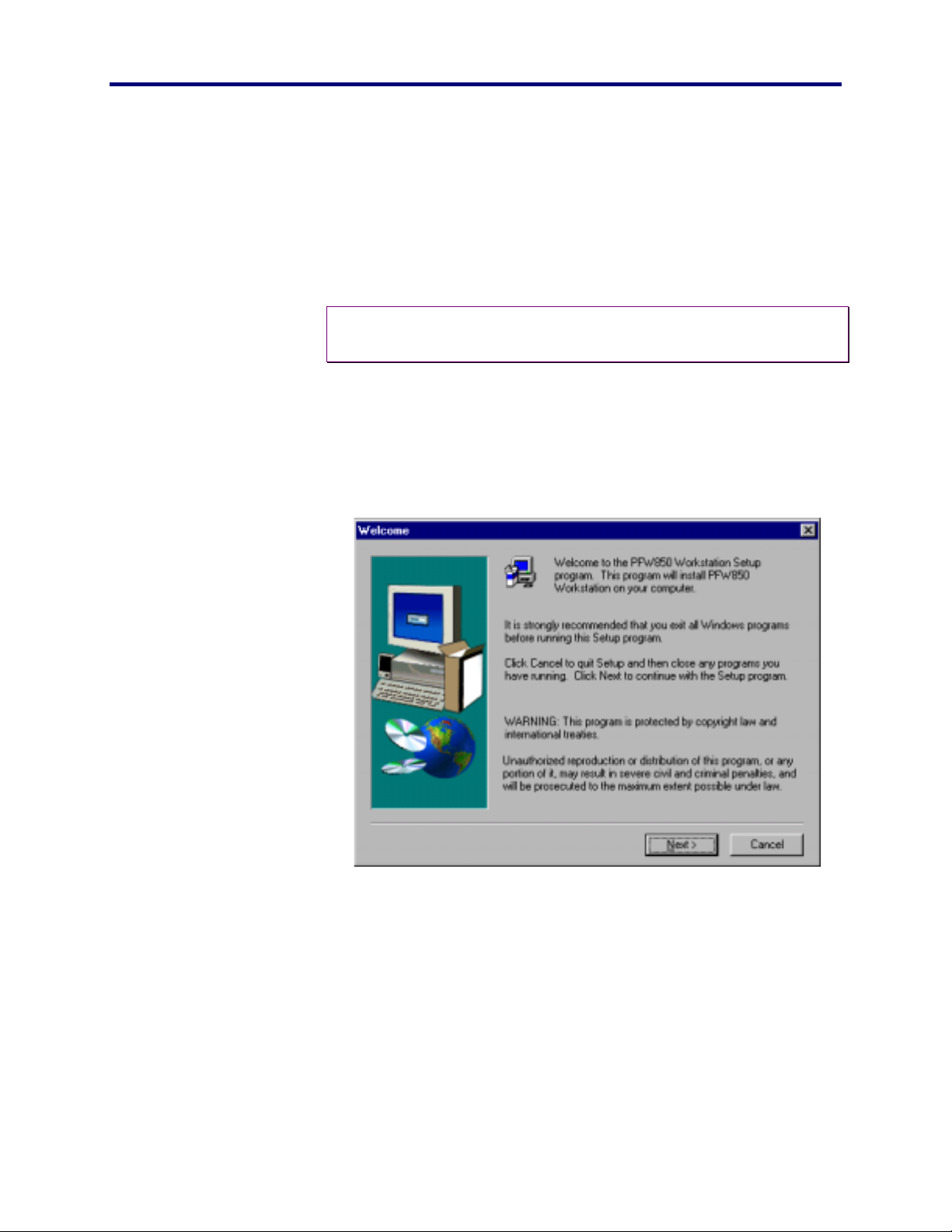
PFW850 Workstation\Setup.exe
This Setup Utility will begin the installation process with the
welcome screen.
PFW850 Workstation
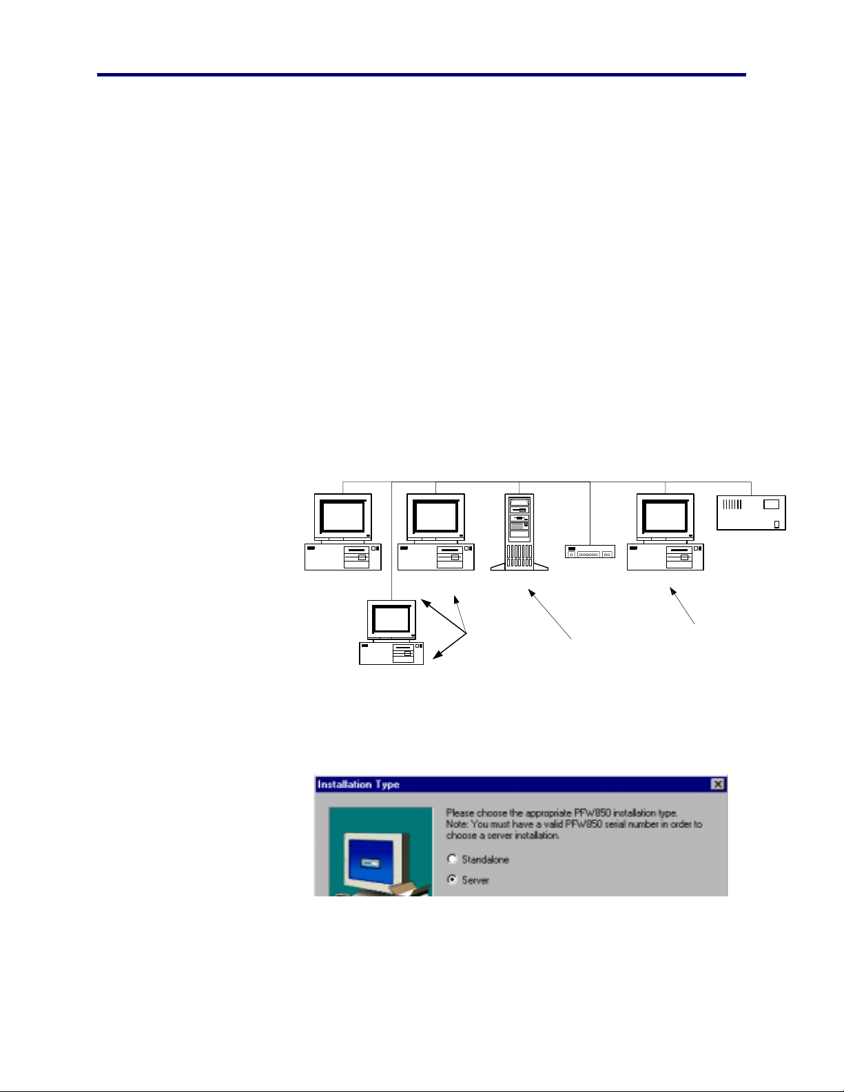
3. Click NEXT
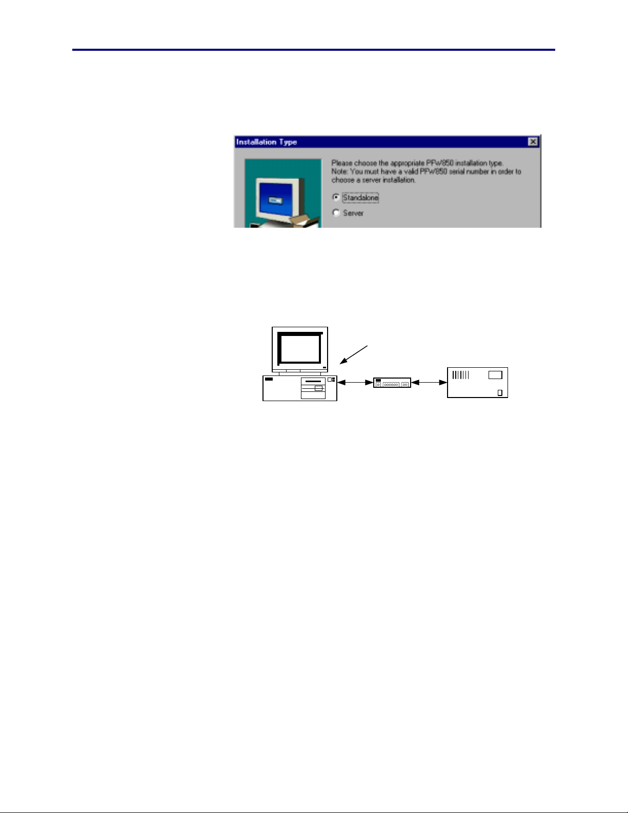
The next choice will be Stand-Alone or Server. Stand-Alone is for a
single licensed user having only one workstation. A server
installation will need a multi-user license key and require a network
file storage server.
The number of PFW850 workstations using the files generated by this
setup utility must not exceed the number of licenses purchased.
For a Stand-Alone version go on to step 4.
For Server installation, skip to step 10.
17 I
NSTALL
Page 18
Stand-Alone Installation
The Stand-Alone version of this application will reside on the same
PC as the setup utility. All database, floorplan, map, macro, trigger,
and readiness level files will be stored on a single PC to be used by a
single user.
All files stored
locally
Ethernet Hub
PFW850 Setup Utility
PFW850 Workstation
SX850 CPU
4. Choose Stand-Alone.
5. Click NEXT
18
Page 19
Panasonic
MECA TDC
NSTALL
I
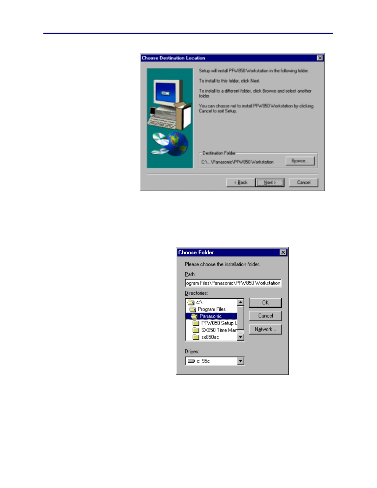
6. If a destination folder is desired other than the
default, type it here, or use the browse button to
select a destination.
7. Click NEXT
PFW850 Workstation
8. Type the location that houses the necessary data
folders or click the browse button.
This location will house the map, macro and readiness level folders
containing the necessary files. These files were created by the
PFW850 Setup Utility and must reside on the local PC hard-drive.
19 I
NSTALL
Page 20
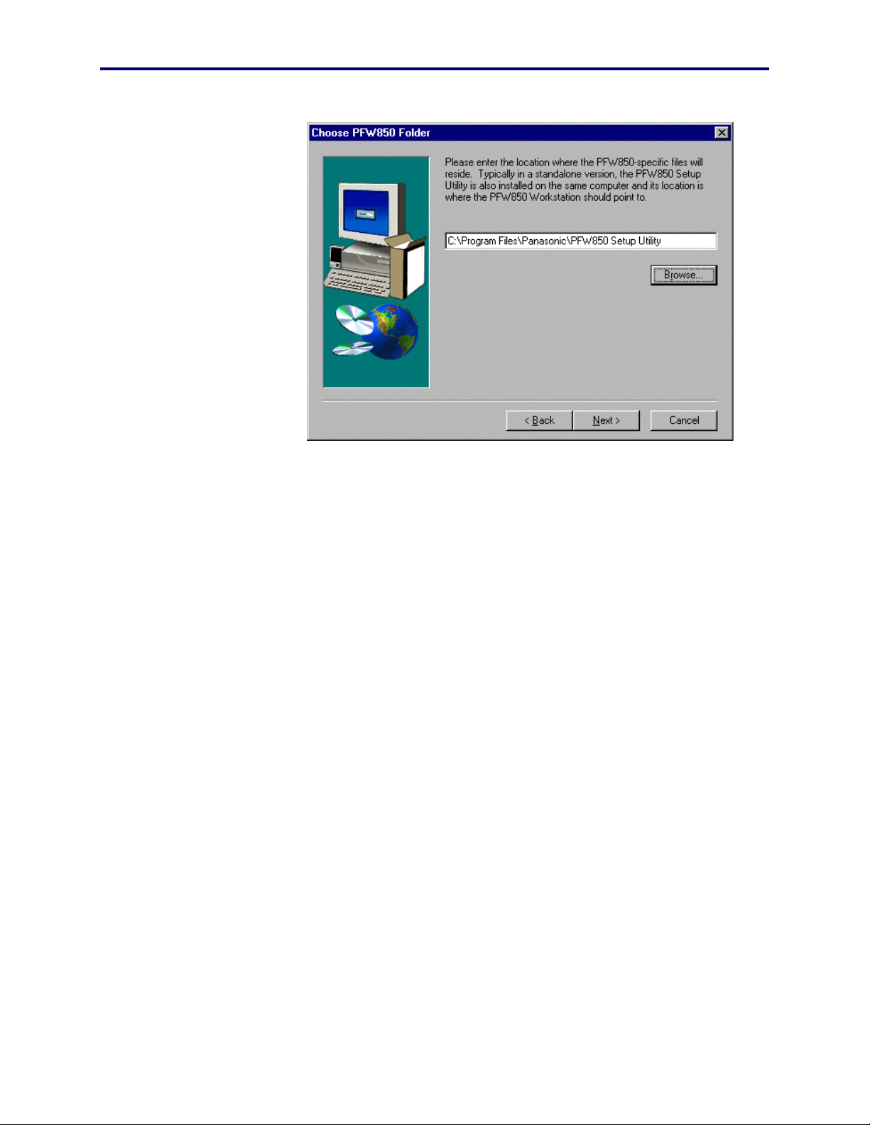
9. Click Next
Go to step 18 to continue installation with Text-to-Speech.
20
Page 21
Panasonic
MECA TDC
Server Installation
The Server version of this workstation application will reside on a PC
other than the setup utility. The intent is to share the map, floorplan,
macro, trigger, and readiness level files with multiple workstation
operators from a network fileserver.
Shared folders in this application is used to update centrally located
files making them readily accessible by all workstations to download
onto their perspective local drives, keeping all databases as up -todate as the Setup Utility.
Each workstation will monitor the server folders every 3 seconds for
changes by way of file comparison. When a difference is detected,
then automatically load a copy of the updated files onto its local harddrive independently.
NSTALL
I
PFW850 Workstation
10. Choose Server
Stored Locallly:
· Databases
Ethernet Hub
Stored Remotely:
· Floorplans
· Maps
· Readiness Levels
· Macros
· Triggers
SX850 CPU
PFW850 Setup UtilityPFW850 WorkstationPFW850 Workstation Server/Shared Drive
Stored Locallly:
· Databases
PFW850 Workstation
11. Click NEXT
12. Enter the
Name, Company and Serial Number
21 I
NSTALL
Page 22
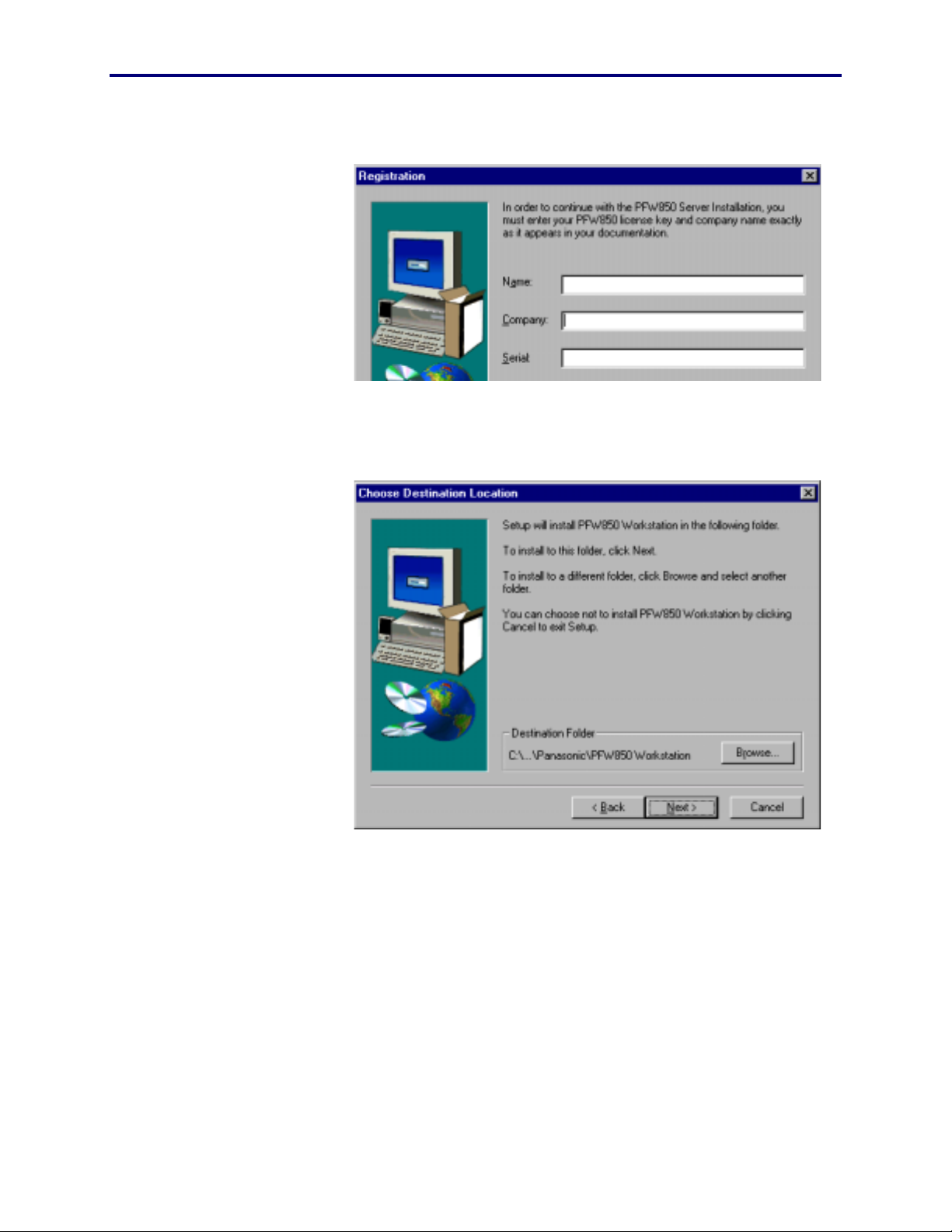
13. Click NEXT
14. If a destination folder is desired other than the
default, type it here, or use the browse button to
select a destination.
22
Page 23
Panasonic
MECA TDC
NSTALL
I
15. Click NEXT
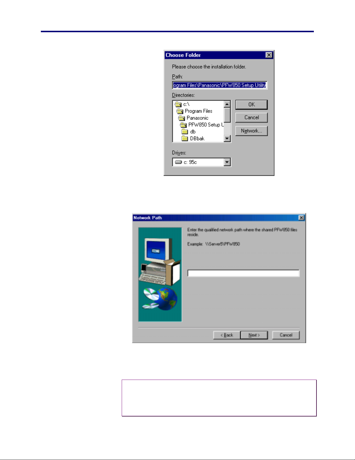
16. Enter the network path in which the shared files are
stored.
PFW850 Workstation
Note: Use the network UNC (universal naming convention) when
♦
entering the network path of the shared files previously installed
by the Setup Utility. See the Setup Utility Installation Manual for
detailed information.
23 I
NSTALL
Page 24

17. Click Next.
To continue the installation with Text-to-Speech, go on to step 18.
Install the Text-to-Speech Engine
To install the text-to-speech engine, read the entire license agreement.
You must agree with the terms in order to install the Text-to-Speech
Engine.
18. Click Yes to agree and continue text-to-speech
installation, or
19. Click No to cancel and continue on to speech
recognition installation.
Warning: If NO is selected, the text-to-speech engine will not
"
be installed, therefore not available.
Install the Speech Recognition Engine
To install the Speech Recognition engine, read the entire license
agreement. You must agree with the terms in order to continue the
Speech Recognition installation.
20. Click Yes to agree and continue the speech
recognition installation, or
21. Click No to cancel the speech recognition installation
and continue Workstation setup.
Warning: If NO is selected, the speech recognition engine will
"
not be installed, therefore not available.
24
Page 25
Panasonic
MECA TDC
Complete the setup
NSTALL
I
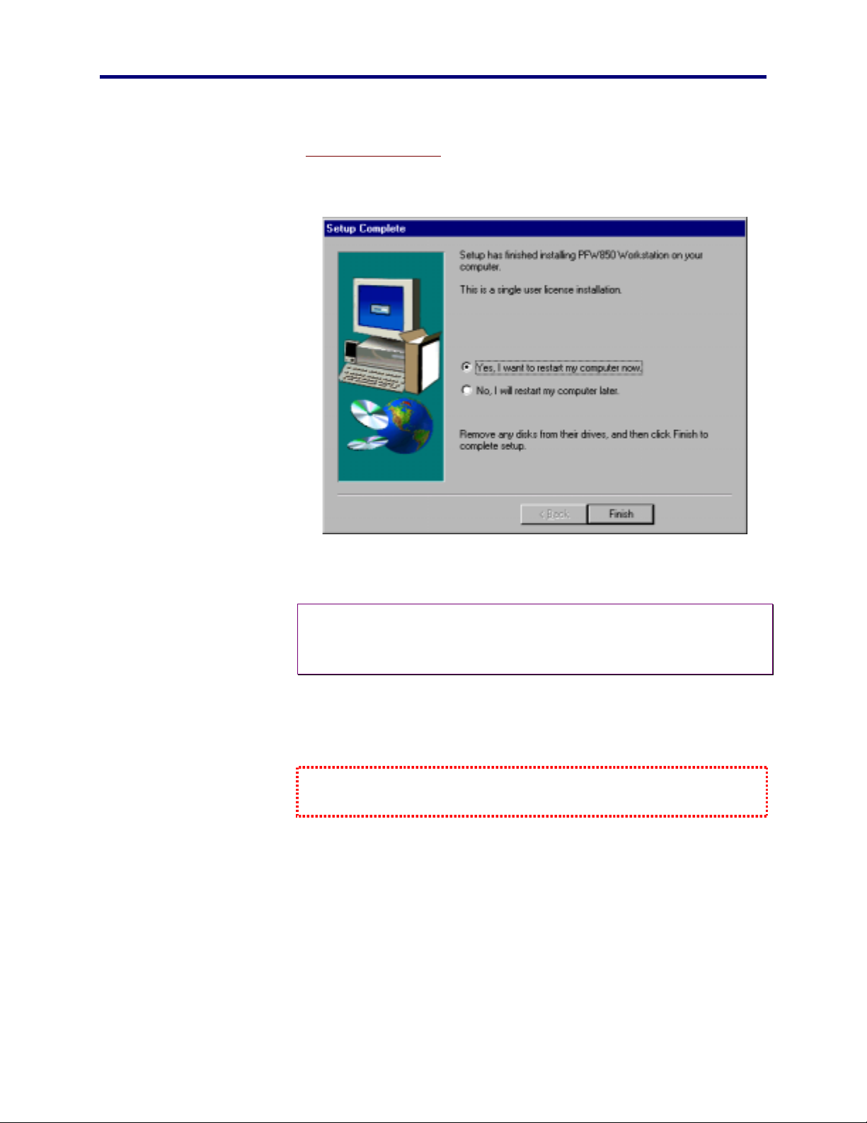
22. Click Yes to restart your computer.
Note: In some cases, such as a re-install, a reboot may not be
♦
necessary. In those cases, the re-boot dialog box will not
appear.
23. Click Finish.
Setup is complete; your computer will restart.
When you are able to come this far without an error, the Workstation
application is installed and operational. Go on to Start Up on page 28.
PFW850 Workstation
25 I
NSTALL
Page 26

FROM DISKETTES
1. Insert diskette 1 into the floppy drive.
2. From the Start menu, select Run.
3. Type
4. Respond to the dialog boxes.
a:\Setup
, then click Enter.
Refer to the Install
26
Page 27

Panasonic
MECA TDC
NSTALL
I
From CD-ROM section on page 17 for information on how to answer the
displayed dialog boxes.
5. Remove each diskette as it finishes, and replacing it
with the next one.
The last one asks you to click Finish in order to complete setup.
When you are able to come this far without an error, the Workstation
application is installed and operational. Go on to Start Up on page 28.
PFW850 Workstation
27 I
NSTALL
Page 28

S
TART
The work in Install, beginning page 15, must be complete before continuing
with this Start Up section.
After installation double-click on the available desktop icon or from
the Start menu, choose Panasonic/PFW850 Workstation.
DATABASE RETRIEVAL
At Startup
At this time, the application will retrieve the current database
information from the active system CPU and display the application
waiting for the operator to login.
U
P
During Operation
To ensure that the PFW850 workstation is always using the current
system data, automatic retrieval is provided. This takes the burden
off the operator to know if the data used is current. So, if the system
CPU databases are changed or updated at anytime during the
operation, the PFW850 workstation will detect a difference and
immediately retrieve a new copy of the databases automatically.
When this occurs, the operator must wait until the download is
complete before continuing operation.
28
Page 29
Panasonic
MECA TDC
LOGIN
TART UP
S
It is necessary for the security specialist-operator to login and out of a
controller for several reasons.
♦
For logging purposes, in the event records are needed.
♦
To insure each operator is subject to permission and class
of service privileges.
♦
To prevent unwanted individuals from controlling system
components.
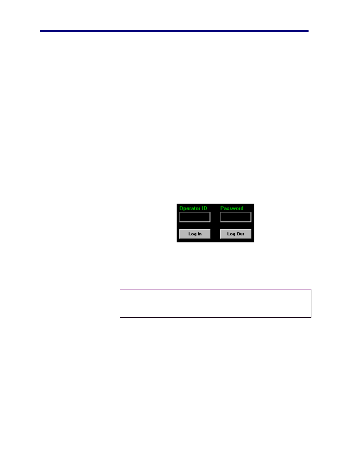
When the PFW850 workstation application opens, you will be
instructed to login.
1. Type your operator ID in the box provided,
2. Type your password.
3. Select the [Log in] button or press [Enter].
The application will validate your ID and password, then open the
main window, displaying the default map.
Note: The PFW850 can, however, act individually as a display monitor
♦
if the operator does not login provided a video card is installed
and connected to the SX850 system.
PFW850 Workstation
29 S
TART UP
Page 30

O
THE MAP
The map on the screen is a detailed representation of the facility under
surveillance, broken into areas or floors that show the location and
identity of possibly every camera and alarm in the system. The map is
planned and configured with icons representing cameras, alarms,
macros and links to other maps using the PFW850 Setup Utility. The
operator should become familiar with the map(s) in order to secure
the areas which (s)he is responsible.
The maps displayed on the screen have built-in intelligence. A map is
smart enough to know if a controller has permission to view its
components. The map will determine the controller -to- component
permissions and draw the icons on the screen accordingly.
For example, a map may have 20 cameras placed strategically by the
administrator during the setup phase. The operator, on the other hand,
may only see 15 camera icons because (s)he does not have the proper
permission to view the missing cameras. Because each PFW850 can
have different permissions, the same map can be slightly different
when viewed on different controllers as far as which components are
displayed and accessed.
PERATION
The section that displays the map on the screen has a dual purpose.
When connected to the system, the map section can switch to video
mode and display camera or recorder views.
In addition, the operator can choose “operator assist” mode, which
changes the map section to display both the map and video
simultaneously. In this case, the operator must manipulate the video
and components via a hardware controller (CU850)
30
Page 31

Panasonic
MECA TDC
THE KEYPAD
The keypad in the PFW850 is available for those operators who wish
to access and control components strictly by using the mouse. When
a section refers to “the keypad”, it means to click with the mouse the
desired numbers instead of the typing method via the PC keyboard.
Number pad
The number pad is available for the operator to click with the mouse
instead of using the PC Keyboard or external joystick.
Enter
The [Enter] key on the keypad works exactly like [Enter] on the PC
keyboard allowing the operator to choose a selection without using
the PC keyboard or trigger on the external joystick.
PERATION
O
Backspace
The backspace key displayed as [BkSp] will remove a character to the
left of the cursor. This works the same as the [Backspace] key on the
PC keyboard.
Clear
The [Clear] key will remove all characters in the highlighted section
allowing the operator to quickly empty the selection and enter another
value.
PFW850 Workstation
31 O
PERATION
Page 32

MAIN MENU
The main menu is available for selection and control of specific
components whether it is or is not visible on a map. Several buttons
are available for the setup of certain components in the system, such
as iris control on a camera. Many of the setup options are used
infrequently and can be accessed via this main menu.
Note: the control and actions will only take place if the proper
♦
permissions and service class privileges are met.
Select actions will describe how to gain access to a specific aspect of
a component. Control actions, on the other hand, will explain the
steps needed to manipulate the selection.
Alarm Control
Alarms play an essential role within an SCS. Alarms can
automatically trigger an event occurrence such as a camera spot or a
tour sequence as well as invoke an action. Actions will allow the
system to open or close a contact in the ALARM IO circuit that, for
example, will start a siren or possibly turn on a spotlight. It will also
alert the operator using a PFW850 controller in the map.
32
Page 33

Panasonic
MECA TDC
PERATION
O
ALARM STATES
The flow chart below will show five of the six possible alarm states.
Armed, Active, Acknowledged, Reset, and Clear. The disarm state is
not shown in the flowchart. The alarm must be allowed in the system
database in order for an operator to select this state. When an alarm is
put in disarmed by the operator, it must be re-armed manually.
No
ARMED
Yes
No
(1) Is Alarm
Triggered?
Is the Alarm
Manually Armed?
No
Yes
ACTIVE
CLEAR
No
Is the Alarm set to
No
(3) Is the Alarm
Acknowledged?
(3) Is the Alarm
Reset?
Yes
Auto Arm?
Yes
Yes
Yes
(2) Is the Alarm
Trigger complete?
ACK
No
RESET
No
(3) Is the Alarm
Reset?
Yes
PFW850 Workstation
Alarm State Decision
(1) Triggered:
Normally Open Contacts are Closed
Normally Closed Contacts are Open
(2) Trigger Complete:
Normally Open Contacts are Open
Normally Closed Contacts are Closed
(3) Can be Manual or Automatic
33 O
PERATION
Page 34

Alarms are color-coded on the map according to the current state,
such as active, armed, etc. The following table will describe the
meaning of each colored state. The clear and reset states are not
represented by a color.
Icon Color Alarm State
Disarmed, deactivated and cannot be triggered.
Blue
Green
Yellow
SELECT ACTIONS
Armed, ready for activation, or to be triggered.
Active, triggered and action has begun.
Red
Acknowledged, recognized but not rearmed.
Select an Alarm
To select an alarm, perform any of the following actions:
♦
If an alarm exists on a map, single-click on the alarm.
Tip: A blinking alarm on a map indicates the alarm is selected by the
•
local PFW850 operator.
♦
Click the [Alarm] button in the main menu, type the
number and click the select button. You may also use the
up or down arrows to select an alarm number.
34
Page 35

Panasonic
MECA TDC
PERATION
O
Note: up and down arrow keys will scroll through only the ID numbers
♦
configured and present in the database retrieved from the
system CPU.
♦
If an alarm is active, single-click on the Alarm tab.
Each active alarm will appear in the Alarm Tab. If active alarms are
present:
!
Double-click on the alarm. This will cause the
associated map to display.
!
This will also automatically select the alarm and
open the alarm window on the left. The operator
can then choose to acknowledge, disarm, or rearm the alarm.
!
When the alarm is selected, movement on the
joystick will manipulate the camera view
associated with that alarm.
!
Most of the PFW850 functions will be disabled
until the alarm is deselected and returned to
normal. See Deselect an alarm for more
information.
♦
Focus on the alarm frame by tab or arrow keys, and then
use the keypad to enter the alarm number.
When an alarm is selected, the status will be visible in the status
window.
Select Next Alarm
To move to the next alarm in a sequence click the alarm button in the
main menu, and then click the [Next] button.
Select Previous Alarm
To move to the previous alarm in a sequence click the [Previous]
button.
PFW850 Workstation
Deselect
When an alarm is selected, click the [Deselect] button in the main
menu window. This will remove the focus from the selected alarm,
allowing the operator freedom to select another alarm, or move to
another component.
35 O
PERATION
Page 36

CONTROL ACTIONS
Acknowledge
An alarm can only be acknowledged if it is active. Select the active
alarm, then click the acknowledge button in the main menu window.
Arm
Either when an alarm is in the disarmed or acknowledged state, select
the desired alarm and click the Arm button.
Disarm
Either when an alarm is in the armed or acknowledged state, select
the desired alarm and click the disarm button.
Reset
Alarm will reset back to the arm state if the following conditions are
met.
♦
Alarm condition not occurring (as an open door triggered
the alarm, but the door is now closed).
♦
Alarm is active or acknowledged
♦
Alarm
is
configured for “auto-arm”
Alarm will reset to the clear state if the following conditions are met:
♦
Alarm condition is not occurring (as an open door
triggered the alarm, but the door is now closed).
♦
Alarm is active or acknowledged.
♦
Alarm
Alarm Output
is not
configured for “auto-arm”.
Alarm output circuits are contacts provided as a momentary output to
enable or disable external devices, such as, a door opener, strobe
light, siren, etc. When an alarm output is selected, the contact will be
enabled for amount of time designated upon system setup.
36
Page 37

Panasonic
MECA TDC
PERATION
O
Select an Alarm Output
1. In the main menu, click on the [Alarm Output] button.
This will allow the operator to select an alarm by using the mouse or
PC keyboard.
2. Then click [Select] or use the [Enter] key.
Alarm output selection will enable the circuit contacts as follows:
!
Normally closed contacts will open.
!
Normally open contacts will close.
After the predetermined dwell time expires, the alarm output circuit
contacts will return to normal or become disabled.
!
Normally closed contacts will close.
!
Normally open contacts will open.
Area Select
An area (monitor surveillance area) is comprised of an array of
monitors and one or more system controllers and used as a tool to
organize a system of large capacity. Each controller is configured as
part of an area that the operator will be responsible to monitor tour
sequences, group presets, and group sequences that will run on
monitors within an assigned area.
An operator logged into a controller will be confined to a specific area
unless “area change” privileges are assigned by the administrator,
only then allowing a cross into another area. This section will explain
the process of changing areas and the limitations if the operator does
not have the privilege.
When the area button is not available (grayed-out) the operator does
not have sufficient area change permission or service class privileges.
If the area button in the main menu is available:
PFW850 Workstation
37 O
PERATION
Page 38

1. Click the [Area] button in the main menu.
2. Select the desired area.
3. Click the [Select] button or press [Enter].
The newly selected area will be displayed in the status box.
The operator is now free to select components or sequence numbers
confined within this selected area.
Camera
A camera is the lifeline within a surveillance system. Each camera is
either identified on a map, or called upon by the operator manually.
Depending upon the system type, there can be as many as 8192
cameras in the system.
Although a camera may be available, depending upon a specific set of
permission, a cameras view or control may be blocked at any given
location.
SELECT ACTIONS
Camera selection is one of the most frequent actions the operator will
make. Because of this, a special selection area is provided, along
with the standard process.
Select a Camera
To select a camera, perform any of the following actions:
♦
If a camera exists on a map, single-click on the desired
camera icon.
Tip: A blinking camera icon on a map indicates that camera is selected
•
by the local PFW850 operator.
This will cause the screen to automatically switch into video mode
displaying for the operator the camera video.
1. In the Camera Select box, enter the number of the desired
camera.
This can be accomplished in several ways.
38
Page 39

Panasonic
MECA TDC
PERATION
O
!
Typing the number in the camera select section with the
PC keyboard.
!
Click the keypad with the mouse.
!
Use the external joystick and enter a number. See
external joystick section for more information
2. Click the Select button or use the [Enter] key.
Note: Camera selection is bound to the database retrieved from the
♦
system CPU. That is only , the numbers displayed are those that
exist within the database, since the last retrieval. See Start Up
on page 28 for database retrieval information.
♦
Focus on the camera frame by tab or arrow keys, and then
use the keypad to enter the desired camera number.
Select Next Camera
♦
To move to the next camera in a sequence, click the
[Next] button in the Camera Select window.
Select Previous Camera
♦
To move to the previous camera in a sequence, click the
[Previous] button in the Camera Select window.
CONTROL ACTIONS
In order to control a specific camera, it must be selected. See select
actions above in the camera section for an explanation of the different
selection options. Keep in mind that there are many different types of
cameras on the market, each possessing different features. The
controls will only operate if the camera has that particular feature,
such as wiper, defrost, zoom, etc. The operator must become familiar
with the types of cameras the (s)he is responsible for monitoring.
PFW850 Workstation
39 O
PERATION
Page 40

There are several different ways to control a camera, provided a
movable camera is selected. Use the mouse and click buttons, use the
mouse and click on the virtual joystick, or use an external joystick.
Virtual Joystick Control
In order to fully control all aspects of the PFW850 using the mouse, a
virtual joystick is provided for camera movement. To control the pan
and tilt features of a camera, click inside the circle and drag to the
edge in the direction desired. The camera will respond as if using a
hardware controller.
Pan
Pan means to move a camera from side-to-side horizontally.
Tilt
Tilt means to move a camera up and/or down vertically.
Zoom
To zoom a camera means to move the lens to wide angle or telephoto
positions. This will bring the video image in for a closer look [Tele],
or move it farther away [Wide] allowing the operator to view a larger
area.
Focus
In order to focus a camera, use the [FAR] and [NEAR] buttons on the
virtual joystick. Click the [AUTO] button to automatically focus a
camera to the closest object detected.
40
Page 41

Panasonic
MECA TDC
PERATION
O
CAMERA CONTROL SETTINGS
Some cameras have features available that are used by an operator
less frequently than the select, zoom, pan/tilt, or focus. The selected
camera must have the feature available and can be accessed by
clicking the camera button in the main menu.
Auto Pan
Setting the Auto Pan feature to ON will cause the selected camera to
automatically move from left to right and back again. This feature
may be used to scan a large area such as a parking lot or auditorium.
The camera will constantly move until one of following is performed:
♦
Auto Pan feature is disabled or turned OFF via the camera
settings.
♦
Move the virtual joystick in any direction.
♦
Move the external joystick in any direction.
Wiper
The wiper feature can be turned on for cameras exposed to the
weather. The operator must select a camera, then turn the wiper on
and/or off via the [ON] and [OFF] buttons.
Defrost
The defrost feature can be turned on for cameras exposed to the
weather. The operator must select a camera, then turn the defroster
on and/or off via the [ON] and [OFF] buttons.
PFW850 Workstation
Aux 1
Some cameras provide auxiliary contacts so external devices can be
accessed manually by an operator or automatically by a macro or
41 O
PERATION
Page 42

alarm. For more information on Auxiliary contacts, see the user
manual supplied with the specific camera model.
Aux 2
Some cameras provide a second set of auxiliary contacts so external
devices can be accessed manually by an operator. See Aux 1 above.
Iris
An operator can control the amount of light that enters the camera
lens by using the iris control, such as open the lens for more light or
close for less light.
Click on the camera button in the main menu, then select the camera
other button to access the iris control. Use the [OPEN] button to open
the lens (allow more light), and [CLOSE] to close the lens (allow less
light). The [AUTO] button is used for automatic iris adjustment.
Camera Menu Options
Some cameras are equipped with an on-screen menu feature. See the
user manual supplied with the camera model that has this feature.
The buttons in this window will correspond with the hardware
controller actions explained in that guide.
42
Page 43

Panasonic
MECA TDC
PERATION
O
To view the camera menu, click the [ON] button. This will turn the
OSD off and turn the Camera Menu on.
Note: The operation of the control buttons may change with each
♦
different camera model. The description below is a general
description, see
.
models
the operators manual for the specific camera
Up/Down arrows:
Right/Left arrows:
Double Right/Left arrows:
Will scroll through menu items on the screen.
Will scroll through settings on the selected item
Will go to another menu depending on the
item or camera model
Reset:
sets the selected menu item to the factory default value.
Use the reset button to also enter the SPECIAL menu on some camera
models.
Reset All:
sets ALL menus to the factory default value.
Camera Preset
Beyond what the System Administrator does when setting up the
SCS, operators of PFW850 workstation establish and identify
individual camera presets to the system. A camera preset is a
particular combination of azimuth (direction), lens focus and, (if a
zoom lens, focal length) and iris setting that yields a certain view.
Having specific presets available will enable the operator to quickly
switch to a specific camera view without having to PTZF manually.
PFW850 Workstation
Note: Not all cameras have preset positioning available, such as non-
♦
moveable cameras. See the manufacturer guide supplied with
each individual camera to determine if this feature included
available and number of presets available.
43 O
PERATION
Page 44

SELECT ACTIONS
Before camera presets can be selected, they must be configured, or
set. To set camera presets see Control Actions below.
Select Preset
After selecting a monitor and camera to display video, use the
following methods to select a preset:
1. Type the desired preset number.
2. Use the up and down arrows to scroll.
3. Use the keypad to select a preset number.
4. Click [Select] or press [Enter].
When a preset selection is made, the camera transmitting video to the
screen will move to the selected preset position. This will not prevent
the operator from controlling the camera.
CONTROL ACTIONS
Set Preset
Select a preset number using a method described in the Select Preset
section. Using the joystick, aim the camera at the desired location
and click the SET button.
Verify setting by moving the camera from its present location and
click select. The camera will return to the position that you set for the
displayed preset number.
Group Preset
A Group Preset is a collection of monitor-camera pairings, whereby
in a single shot, a group of monitors will display video output from
cameras at specific preset positions.
44
Page 45

Panasonic
MECA TDC
PERATION
O
SELECT ACTIONS
Select Group Preset
When selecting a group preset, the selection will be confined within
the same MSA (monitor surveillance area) as the controller. If the
operator wishes to select a group preset in another controller’s MSA,
(s)he must enter that area before selecting the group preset. See
Area Select on page 37.
1. Click the [Group Preset] button in the main menu.
2. Type the desired group preset number or use the up
and down arrows to scroll to the desired number.
Note: Group Preset selection is bound to the database retrieved from
♦
the system CPU. That is only , the numbers displayed are those
that exist within the database in a specific MSA, since the last
retrieval. See Start Up on page 28 for database retrieval
information.
3. Click the [Select] button or press [Enter].
PFW850 Workstation
45 O
PERATION
Page 46

Group Sequence
A Group Sequence is an automated series of Group Presets. It
combines several Group Presets, separated by specific periods of time
called Dwells.
SELECT ACTIONS
When selecting a group sequence, the selection will be confined
within the same MSA (monitor surveillance area) as the controller. If
the operator wishes to select a group sequence in another controller’s
MSA, (s)he must enter that area before the selection is made. See
Area Select on page 37.
Select Group Sequence
1. Click the [Group Sequence] button in the main menu.
2. Type the desired group sequence number or use the
up and down arrows to scroll to the desired number.
Note: Group Sequence selection is bound to the database retrieved
♦
from the system CPU. That is only , the numbers displayed are
those that exist within the database in a specific MSA, since the
last retrieval. See Start Up on page 28 for database retrieval
information.
3. Click the [Select] button or press [Enter].
The group sequence will run in order of how the group presets were
entered into the database by the administrator. The group sequence
number followed by an “R” will be displayed in the OSD of the
monitors involved.
Stop Group Sequence
Stops the group preset from running; cancels the action. The group
sequence number will be removed from the OSD.
46
Page 47

Panasonic
MECA TDC
PERATION
O
Joystick Settings
It may be necessary to change the settings of the external joystick (for
recommended model see Optional hardware in the Platform section
on page 16) and the virtual joystick to the operator preference.
Standard
This setting will affect the both external and virtual joysticks. Select
STANDARD to cause movement to be the typical, as up is up and
down is down.
Reverse
This setting will also affect both external and virtual joysticks. Select
REVERSE to cause the movement to be opposite the standard
movement, as up is down and down is up. Much like the flight
control of video games.
Dead Zone
Dead zone will affect the external joystick sensitivity only.
A higher number percentage will cause the joystick to become less
sensitive, that is increasing the dead zone creating larger range of play
(no camera movement) from center to the outer limit.
A lower number percentage will cause the joystick to become more
sensitive, that is decreasing the dead zone creating a smaller range of
play (no camera movement) from center to the outer limit.
PFW850 Workstation
47 O
PERATION
Page 48

Login/Logout
OPERATOR LOGIN
In order to view a map or any video onto the PFW850, or control
components, an operator must login with an ID and password. When
an operator will be away from the controller, (s)he should logout.
This will prevent unauthorized users from accessing the system.
OPERATOR LOGOUT
Using the mouse, simply click on the logout button. The user is
immediately logged off the system. The map will be removed,
however, the video will remain and the PFW850 can continue to be
used as a standard monitor, to be used by another controller.
See the
48
Page 49

Panasonic
MECA TDC
PERATION
O
Login on page 29 for information on how to re-enter or login to the
system.
Monitor
A Monitor is generally described as a CRT (cathode ray tube)
dedicated to viewing images generated by one or more of the
components of surveillance system. In this case, the PFW850 has
video capabilities and can be selected as a monitor, assuming the
proper hardware (happauge video card) is installed and is connected
to the SCS. This workstation is also capable of selecting other
monitors connected to the system, keeping in mind the MSA,
permission, priority, and class of service privileges.
SELECT ACTIONS
When selecting a monitor, the selection will be confined within the
same MSA (monitor surveillance area) as the controller. If the
operator wishes to select a monitor in another controller’s MSA, (s)he
must enter that area before the selection is made. See
Area Select on page 37.
PFW850 Workstation
49 O
PERATION
Page 50

Select Monitor
Monitor selection is one of the most frequent actions the operator will
make. Because of this, a special selection area is provided, along
with the standard process.
To select a monitor, perform the following actions:
1. Type the monitor number or
2. Use the up and down arrow buttons to scroll to the desired
monitor ID number.
3. Click the [Select] button or press [Enter].
Note: Monitor selection is bound to the database retrieved from the
♦
system CPU. That is only , the numbers displayed are those that
exist within the database in a specific MSA, since the last
retrieval. See Start Up on page 28 for database retrieval
information.
♦
Focus on the monitor frame by tab or arrow keys, and
then use the keypad to enter the desired monitor number
and press [Enter].
Select Next Monitor
To move to the next monitor in a sequence, click the [Next] button in
the monitor Select window.
Select Previous Monitor
To move to the previous monitor in a sequence, click the [Previous]
button in the monitor Select window.
50
Page 51

Panasonic
MECA TDC
PERATION
O
CONTROL ACTIONS
In the main menu, select the monitor button. The following control
actions are available to the operator.
Monitor Lock
It is possible to lose control of a seized monitor due to the last come,
first serve rule. Because of this rule, an operator can inadvertently
accept or lose responsibility of specific cameras or alarms that are
displayed on a monitor. To avoid this, the operator is able to lock a
monitor, preventing the rule. Upon locking a monitor, the operator
prevents other operators with the same or lower priority from seizing
the locked monitor. An “L” will be displayed on the locked monitor,
which will alert other operators that the monitor is unavailable.
In this case, the operator can lock a monitor and move on to another
monitor leaving the specified monitor in the locked condition,
however, after controlling components displayed on particular
monitor, the operator should unlock his or her locked monitor. This
will allow other operators to seize that particular monitor. If the
operator logs out of the controller, all monitor locks enabled by the
operator will be removed.
In order to lock a monitor, the operator must seize the desired monitor
(see Select Monitor) and click the Monitor button in the main menu.
Then click the Monitor Lock ON button. An “L” will be displayed
showing that the monitor is locked. To unlock a monitor, make sure
that the monitor is seized and click the Monitor Lock OFF button.
The displayed “L” will be removed indicating that the monitor is open
for other operators.
OSD functions
Each monitor will show textual information about the component
being displayed. The operator is permitted to show or hide any or all
of the following information:
♦
Global OSD: All textual information shown on the screen
will be displayed or hidden when using the [ON] or [OFF]
buttons respectively. OSD settings will have no affect on
PFW850 Workstation
51 O
PERATION
Page 52

the camera number, time, and date and cannot be turned
off.
♦
Camera Title: Display or hide Camera number and Name
(given by the administrator) by using the [ON] or [OFF]
buttons.
♦
General Status: Tour and alarm information as well as
which keyboard has the monitor seized can be displayed
or hidden using the [ON] or [OFF] buttons.
♦
Monitor Status: Monitor number and area associated with
the particular monitor can be displayed or hidden by
using the [ON] or [OFF] buttons.
Recorder
Recording devices can, as an option, be connected to the surveillance
system. If the optional recording feature is available, the operator
may view and control the actions of specified video recording
devices, such as VCRs. Although a recorder may be available,
depending upon a specific set of permissions, a recorder’s view or
control may be blocked at any given location.
SELECT ACTIONS
A recorder in play mode acts as a camera in the system, displaying
video onto a monitor. However, it is possible to control or review the
video in the same manner as you would on your VCR at home.
Select Recorder
Recording devices connected to the system can be manipulated in the
same manner as you would using the remote control at home. Select
the recorder using the following method:
1. Click the [Recorder] button in the main menu.
2. Type the desired recorder number or use the up and
down arrows to scroll to the desired number.
3. Click the [select] button.
4. Select a control action.
52
Page 53

Panasonic
MECA TDC
PERATION
O
Record
Stop
Pause
Play
Fast
forward
Rewind
Step
Forward
Select Next Recorder
To move to the next recorder in a sequence click the [Recorder]
button in the main menu, and then click the [Next] button.
Select Previous Recorder
To move to the previous Recorder in a sequence click the [
Recorder] button in the main menu, then click the [Previous] button
CONTROL ACTIONS
When selecting a control action, the selected monitor will display the
action accordingly to let the operator know which action is being
performed.
PFW850 Workstation
Power On
Turns the power on to the selected recorder.
Power Off
Turns the power off to the selected recorder.
Stop Play
Stops the control action, such as play, fast forward, and rewind on the
selected recorder.
53 O
PERATION
Page 54

Pause
Pause a recorder play action to temporarily put the action at rest.
Play
Runs the videotape to review the video recorded.
Rewind
Wind back in reverse the videotape on the selected recorder.
Fast Forward
Advance rapidly forward the videotape on the selected recorder.
Step Forward
Advance forward on a frame-by-frame basis the video on the selected
recorder when in pause mode.
Record
Reproduce the video transmitted by a specific camera on the selected
recorder.
54
Page 55

Panasonic
MECA TDC
PERATION
O
Speech Settings
TEXT-TO-SPEECH
Text-to-speech is an optional feature supplied with the PFW850
installation Disk. This enables the operator to hear the goings-on of
the system without actually selecting components. Such as when a
database update is being performed, an alarm becomes active, video is
lost the system will respond by speaking to the operator the activity.
Here the operator will enable/disable the text-to speech feature, as
well as control the speed at which the voice speaks.
These settings will not be available if the text-to-speech engine has
not been installed. See the Install the Text-to-Speech Engine on
page 24 for installation information.
Speech Response Enable/Disable
If installed, click on the [Speech Settings] button. To enable or
disable this feature using the [ON] and [OFF] buttons provided. By
default, this feature is turned on.
PFW850 Workstation
Speed
The speed of the spoken voice can be changed using the slide bar to
slow or speed up the speaking voice in this feature. Each operator
will manipulate or control the system at his or her own speed, the
speed control is available for the operator to customize the PFW850
workstation. This is a personal preference and can be changed as
different operators login, such as shift changes.
55 O
PERATION
Page 56

SPEECH RECOGNITION
The PFW850 allows several ways to manipulate the system. Along
with automatic macros, or using the mouse, keyboard, or external
joystick controls, speech recognition is available. With the required
hardware (sound card & microphone) installed, the operator can
simply speak specific commands and the system will recognize those
commands and respond accordingly.
These settings will not be available if the text-to-speech engine has
not been installed. See the Install the Speech Recognition Engine
on page 24 for installation information.
Enable/Disable
If installed, click n the [Speech Settings] button. To enable or
disable this feature using the [ON] and [OFF] buttons provided. By
default, this feature is turned off.
Microphone
In order for speech recognition to work, a microphone is necessary.
There are many different type, shapes, and sizes at all costs. Consider
the environment and determine what type of microphone is needed.
When a microphone is chosen, it will be necessary to calibrate it to
the operators voice.
Buying a microphone for speech recognition
One of the best ways to increase accuracy for speech recognition is to
have the right microphone. Here is a list of the different types of
microphones and some information about them.
♦
Built-into the computer/monitor - Microphones built-into
computers or computer monitors work for command &
dictation because they are too far away and pick up a lot
of noise.
♦
Built-into the keyboard - Microphones built-into
keyboards do not work well for speech recognition
because they are too far away and pick up a lot of noise.
♦
Clip-on - Clip-on microphones clip onto your shirt, just
microphones. In addition, the cord sometimes gets in the
way.
56
Page 57

Panasonic
MECA TDC
♦
Close-talk - You wear close-talk microphones on your
head so that the microphone is as close to your mouth as
possible. These work the best for speech recognition and
dictation because they hear only the person speaking and
not any background noise. Unfortunately, the cord
sometimes gets in the way.
♦
Desktop - Desktop microphones usually rest in a
microphone stand. If you keep the microphone pointing
towards you and about 6" (15cm) from your mouth, they
work well, but only in quiet rooms.
♦
Earpiece - Earpiece microphones rest on your ear. These
work well for speech recognition and dictation but not as
well as close-talk microphones. Unfortunately, the cord
sometimes gets in the way.
PERATION
O
♦
Hand-held - Although hand-held microphones pick up
very little noise, they are not convenient for most speech
recognition purposes because they must be held 4" (10
cm) away from the user's mouth.
♦
Handset – These microphones look like normal telephone
handsets, but they plug into the microphone jack rather
than the telephone jack. Handsets get good accuracy.
♦
Rest on the computer - Microphones that rest on the
computer do not work well for dictation because they are
too far away and pick up a lot of noise, but they will work
for command and control.
You can buy a microphone from many local electronics and computer
stores, or mail order it. When buying a microphone, you should
consider the following:
♦
How much are you willing to pay? Very cheap
microphones do not provide good recognition accuracy.
Although high-priced microphones will get slightly higher
accuracy compared to mid-priced microphones, most of
the benefit is in additional comfort and noise-resistance.
PFW850 Workstation
57 O
PERATION
Page 58

♦
Where will you be using speech recognition? If you are
speaking in a quiet room, a close-talk or handset
microphone is best, but other types of microphone (e.g.
desktop) may also give good results. However, if you are
speaking in a noisy room or a cubicle environment, a
close-talk or handset microphone is essential for good
performance.
♦
Is the microphone comfortable? If you have to wear a
microphone, make sure it’s comfortable since you may be
wearing the microphone for several hours each day.
♦
Will the microphone work with your sound card? Not all
microphones work with all sound cards. You should refer
to your sound card’s documentation for a list of
compatible microphones. If it doesn’t contain a list, then
look for microphones specifically designed to be used
with computers.
Calibrate the microphone
In the main menu, click on the speech settings button.
Under the Speech Recognition, click on the Mic button.
This will start the microphone wizard. Follow the steps and answer
the questions correctly. Use the on-line help for further information
on installing and calibrating the microphone.
Commands
In order for the PFW850 Workstation to recognize the specific
commands, the operator must speak the intended number, followed by
the component. Such as “One-thousand one; Camera”. The number
will be displayed in the number field of the keypad when recognized,
then when the component command is spoken, the number will be
inserted into the correct field and the intended choice will be selected.
The operator must keep in mind, the permissions and service class
privileges of which (s)he is restricted. If a permission is denied the
desired component, the PFW850 Workstation will ignore the spoken
command.
Supported Commands
!
Camera
!
Preset
!
Monitor
!
Group Preset
58
Page 59

Panasonic
MECA TDC
PERATION
O
!
Group Sequence
!
Tour Sequence
!
Area Select
!
Alarm
!
Alarm Output
!
Recorder
Tour Sequence
A Tour Sequence is an automated sequence of steps, whereby, in a
single shot, a single monitor displays video output from a series of
cameras that have gone to specific preset positions. A tour sequence
can be invoked in several ways, manually called by an operator,
automatically by a macro, or automatically by an alarm action.
SELECT ACTIONS
When selecting a tour sequence, the selection will be confined within
the same MSA (monitor surveillance area) as the controller. If the
operator wishes to select a tour sequence in another controller’s MSA,
(s)he must enter that area before the selection is made. See
Area Select on page 37.
Select Tour Sequence
Select the tour sequence using the following method:
1. Click the [Tour Sequence] button in the main menu.
2. Type the desired tour preset number or use the up and
down arrows to scroll to the desired number.
Note: Tour Sequence selection is bound to the database retrieved from
♦
the system CPU. That is only , the numbers displayed are those
that exist within the database in a specific MSA, since the last
retrieval. See Start Up on page 28 for database retrieval
information.
PFW850 Workstation
3. Click the [Select] button or press [Enter].
4. Select a control action.
59 O
PERATION
Page 60

Cancel
Run Forward
Increment
Pause
Run Reverse
Decrement
The tour sequence will run in order of how the cameras were entered
into the database by the administrator. The tour sequence number
followed by an “R” will be displayed in the OSD of the monitors
involved.
Select Next Tour Sequence
To move to the next tour in sequence perform the following:
1. Click the [Tour Sequence] button in the main menu,
and then click the [Next] button.
2. Select a control action.
A “T” and the selected number followed by “R” will be displayed on
the OSD of the monitors involved in the selected sequence indicating
which group sequence is running.
Select Previous Tour Sequence
To move to the previous tour in sequence perform the following:
1. Click the [Tour Sequence] button in the main menu,
and then click the [Previous] button.
2. Select a control action.
A “T” and the selected number followed by “R” will be displayed on
the OSD of the monitors involved in the selected sequence indicating
which group sequence is running.
CONTROL ACTIONS
Cancel Tour Sequence
Stops the tour from running, cancel the action. The tour sequence
number will be removed from the OSD.
60
Page 61

Panasonic
MECA TDC
PERATION
O
Pause tour Sequence
Pause a tour sequence to temporarily put the action at rest. A “P” will
be displayed on the OSD of the monitors displaying the tour
sequence.
Resume Tour Sequence
Click the [RUN FORWARD] or [RUN REVERSE] button to
continue a tour sequence that has previously been paused. An “R”
will now be displayed in the OSD to indicate the tour sequence in
again running.
Run Tour Sequence in Forward
Runs the selected tour sequence in the order that is placed in the
system database. In other words, the tour sequence will run in the
same order of how the cameras were entered into the database by the
administrator. The tour sequence number followed by an “R” will be
displayed in the OSD of the monitors involved. There is no
indication of which order, forward or reverse, the tours are running.
Run Tour Sequence in Reverse
Reverse the order in which a particular tour Sequence will run. In
other words, the tour sequence will run in the opposite order of how
the cameras were entered into the database by the administrator. The
tour sequence number followed by an “R” will be displayed in the
OSD of the monitors involved. There is no indication of which order,
forward or reverse, the tours are running.
Increment Tour Sequence
Step up the tour Sequence to the next ID number within the area.
This will not automatically stop the current Sequence running. It will
simply initiate the next sequence in order, provided permission is
granted.
PFW850 Workstation
61 O
PERATION
Page 62

Decrement Tour Sequence
Step down the tour Sequence to the next ID number within the area.
This will not automatically stop the current Sequence running. It will
simply initiate the next sequence in order, provided permission is
granted.
Video Capture
Video capture is a tool that the operator can use to take a snapshot of
the current video frame displayed in the local PFW850 window. This
feature can be very useful in surveillance system, as the snapshot will
be saved in BMP file format and then can be emailed, saved to
diskette and recalled for future use.
To capture a snapshot of the current video displayed, perform the
following steps:
Select a camera view using the local PFW850 monitor.
ACTIONS
Click on the VIDEO capture button in the main menu.
This will open the video capture options window and if a map is
displayed, automatically switch to video mode. Use the following
buttons to capture a snapshot of the live video frame, refresh the file
list, view a previously captured still picture, or end the video-snapshot
view. Click the MAIN button to return to the main menu.
62
Page 63

Panasonic
MECA TDC
PERATION
O
Capture
Takes a snapshot, of the video displayed in the video window. It will
automatically save the snapshot to a file in the PFW850
Workstation/Capture folder on the local PFW850 hard-drive.
The snapshot filename will consist of PC date and time on which the
snapshot was taken.
Warning: The filename will reflect the current date and time of
"
the Local PFW850 windows setting. For information
on changing the Windows setting see the Windows
user guide supplied with the local PC.
View
In order to view a snapshot previously captured, double-click on the
desired filename or click to highlight the desired BMP file in the list
and click the VIEW button. This will cause the video window to
change from live video to the snapshot chosen.
End View
After a snapshot has been captured, or viewed, the operator must click
the END VIEW button in order for the video window to close the
snapshot and return to the live video feed transmitted from the
selected camera.
Refresh
If, for any reason, the files have been moved, added, or deleted, the
Video Capture & Review window will not reflect the changes. The
operator must click the REFRESH button to update the file list.
Delete
The delete feature is available for the operator to remove a capture
file when it is no longer needed. The delete button is available for the
operators convenience, so that (s)he does not have to manipulate the
files through the windows explorer. Here, the snapshot can be viewed
before the decision to delete is made.
Highlight the desired capture file and click the delete button.
Warning: This will permanently remove the file from the
"
Workstation hard-drive. There are no restore
feature available.
PFW850 Workstation
63 O
PERATION
Page 64

Video Settings
Set the video that will be processed by the installed video card in the
local PFW850 workstation PC. This window will only be available if
the recommended Happauge video card is installed.
The selections may vary according to the version of Happauge video
card installed. Not all versions perform the same functions. Refer to
the installation manual included with the video card installed.
CONFIGURE
These settings will vary according to the video card installed. Refer
to the installation manual included with the installed video card.
Click on the buttons available to enable or disable specific video
formats and input types supported by the video card version.
IMAGE CONTROL
These settings will vary according to the video card installed. Refer
to the installation manual included with the installed video card.
Slide bars are provided for the operator to click and drag to increase
or decrease the perspective option. Use the default button to set all
options at 50 percent.
64
Page 65

Panasonic
MECA TDC
CURRENT STATE
Whether selecting a camera, monitor, alarm, sequence, etc. the
window shown below will display the current state of each
component. Each item will display either the selected ID and/or its
current state. See each section individually for a detailed explanation
of component states.
In addition, when using the external joystick, this window will be
used to control components and make selections. See External
Joystick section for more information on selecting components.
PERATION
O
PFW850 Workstation
Alarm:
!
Displays the ID number, state, and contact
information of the currently selected alarm
Area:
!
Displays the area that the PFW850
workstation is confined to or current area selected
by the operator.
Camera:
!
Displays the logical number of the
selected camera.
Camera Preset:
!
This field is used for the external
joystick to select a camera preset for the camera
displayed. There is no indication of current status
displayed in this field.
Group Preset:
!
This field is used for the external
joystick to select a group preset. There is no
indication of current status displayed in this field.
Group Sequence:
!
This field is used for the
external joystick to select a group sequence.
65 O
PERATION
Page 66

!
!
!
!
ASSIST MODE
There is no indication of current status displayed
in this field.
Monitor:
Displays the current selected local
monitor number within the displayed area.
Operator ID:
Displays the Operator ID number
and name currently logged into the PFW850
Workstation.
Recorder:
Displays the selected Recording device
and its current state presented (such as PLAY,
REWIND, etc.) on the chosen monitor.
Tour Sequence:
Displays the selected Tour
Sequence local number its current state presented
(such as RUNNING, PAUSE, etc.) on the chosen
monitor within the displayed area.
When placing the PFW850 into Operator Assist Mode, it will display
simultaneously, the map and video that must be controlled by a
hardware keyboard. This allows an operator to view the location of a
camera and/or alarm while also being able to view the video at the
same time. Because of the limited desktop space, components cannot
be controlled by the mouse or external joystick in this mode. The
operator must access components using a hardware keyboard.
The operator, from a hardware controller (CU-850), must access the
monitor designated for the PFW850. The Workstation must also be
set in the Operator Assist mode. The operator would select
components normally. The advantage of the Operator Assist mode is
the map will be visible for the component selected, and the status
messages for system, alarm, macro, and video loss will still be
available.
When the PFW850 workstation is in the Operator Assist mode, the
operator is prevented from manipulating the components from the
application itself. To restore the applications operation, select normal
mode.
66
Page 67

Panasonic
MECA TDC
STATUS TABS
The status section is divided into tabbed windows in order to report
messages that will be important to the operator. When a message
occurs, a beep will sound alerting the operator that a message has
been received. In most cases, when a message is present, the
appropriate tab will come to the front to allow the operator quick view
of the situation.
The operator can also click on the tab to view messages in the
following sections.
PERATION
O
System Status
The system status tab will display all messages pertaining to the
PFW850 system operation.
The following message types will be displayed:
General system messages
♦
: Displays when a system
error occurs. When this type of message occurs, the
system has detected a fault and the operator should
contact service personnel.
Operator interaction messages
♦
: Displays when the
operator attempts an action that is invalid or not allowed.
Such as selecting a camera that does not exist or selecting
a camera without the proper permission. Also displays
when the workstation changes status or information must
be relayed to the operator. Such as when a login is
successful, the voice response feature is enabled or
disabled, etc.
File transfer messages
♦
: Displays when a file transfer
occurs or is expected. File transfers occur when maps,
macros, readiness levels, triggers, or floorplans are
changed in the specified shared folder. Also, databases
are retrieved from the active system CPU each time the
application is started or when a change is detected.
Messages are reported for successful retrieval or when a
problem occurs.
PFW850 Workstation
67 O
PERATION
Page 68

The operator should become familiar with what these messages mean
because they will not remain on the screen. The messages will be
displayed for 8 seconds, then will be removed. Some messages can
be very important and let the operator know that a malfunction has
occurred. Keep a pencil and paper nearby and write down these
important messages. Service personnel may need to know what
messages have been displayed in order to determine a problem. See
the System Messages section for a complete description of the
messages.
Macro Status
Reports each macro action executed by this workstation and displays
if the step was successful or displays an error if any step cannot be
executed. This section will also report the macro name, status, and
start and end times of the executed macro.
Video Loss
Reports video loss from any camera in the system that has been
configured in the system CPU database. The installer may have to
adjust the video loss threshold within the Admin Console in order to
eliminate erroneous messages.
68
Page 69

Panasonic
MECA TDC
PERATION
O
Active Alarms
Because not all alarms appear on the displayed or any map, active
alarms will be reported and can be viewed in this section. Doubleclick on the alarm in the list to automatically select and open the
alarm window in the main menu. The operator can then perform the
desired alarm action, such as acknowledge, reset, etc.
Also, When using multiple maps, double-click on the active alarm.
The PFW850 will search the maps for the selected alarm. If the alarm
appears on a map, that map will be displayed automatically and the
alarm selected.
The alarm must be deselected to return the PFW850 to normal
operation.
Timed Macros
Reports all macros that will be executed by this workstation on a
timed basis. When the specified time and date occurs, use the macro
tab to view the status of the macro steps to insure that each step was
executed correctly.
PFW850 Workstation
69 O
PERATION
Page 70

Readiness Level
A readiness level is a specific group that macro/trigger pairs are
assigned. Each pair must have a readiness level appointed that will
have been previously created by the administrator.
This workstation will monitor the designated triggers assigned to the
level displayed here, and when detected, will execute its associated
macro. The operator may click on another readiness level to change
the level at which the workstations will monitor the designated
triggers, however is not recommended unless otherwise instructed by
a supervisor or administrator.
A readiness level will be assigned macros that a particular
workstation will run when it detects the associated trigger. For
example, when a specific alarm is detected, the assigned workstation
will perform actions designated by the macro instructions and display
certain camera views on specific monitors automatically. The
workstation will only perform the macro actions when the designated
readiness level is displayed. So, careful planning is needed on the
administrator’s part, and the operator should not change the readiness
level unless standard operating procedures warrant the change. See
the Macro Execution section for further information.
70
Page 71

Panasonic
MECA TDC
PERATION
O
About
Display general information about this software, such as version
number. In addition, the IPA displayed is the address of the active
system CPU.
PFW850 Workstation
71 O
PERATION
Page 72

MACRO EXECUTION
A macro can be executed in two different ways. If a macro icon
exists on a map, it can be manually executed by the operator.
Macros can be automatically executed by workstation according to
the configuration setup by the administrator using the Setup Utility.
It will also provide a mechanism to configure actions that take place
automatically (behind the scenes) based upon specific events called
Macros. The events that invoke the administrator defined actions are
called triggers and will run a macro according to pre-defined
readiness levels.
The readiness levels will enable an administrator to define actions
which will only be used within the specified level, thus allowing for
pre-defined actions to take place during critical times or in critical
spaces, while ignoring events that happen during normal conditions.
Macros defined will invoke a series of actions automatically such as,
placing a camera view onto a monitor or running a Tour Sequence on
a particular monitor. Macros can be triggered manually by an
operator when placed on a map, or run automatically when specific
events occur, such as a door opening, or motion detected. Macros
should be well planned taking into account permissions, areas,
privileges, etc.
72
Page 73

Panasonic
MECA TDC
XTERNAL JOYSTICK
E
J
OYSTICK
Components of the SX850 Security Surveillance System can be
controlled several ways explained in previous sections. This section
will discuss control using an external joystick, specifically the MS
Sidewinder Precision Pro model.
Shown below is the button mapping associated with the
recommended external joystick. The buttons used are the Hat Switch,
Button 1 (trigger), Buttons 2, 3 and 4 only. All other buttons are not
used.
(E
XTERNAL
)
PFW850 Workstation
73 E
XTERNAL JOYSTICK
Page 74

Component Selection
Change Number
The status window shown below has a dual purpose. It will show the
status of several different components, as well as serve as a
mechanism to select components solely with the external joystick.
Follow the description in the paragraphs below for information on the
button mapping and directions for using the status window and
external joystick.
1. Using the Hat Switch, move the switch to the right or left to
move the cursor to a desired component location in the
status window.
The desired component section will turn red to show the operator
which is the component to be changed.
Hat switch
Select Function
Point Of View
2. Then move the hat switch up or down to the desired
component number.
3. Finally, press the trigger [Enter] button to make the selection.
74
Page 75

Panasonic
Focus Near
Focus Far
MECA TDC
XTERNAL JOYSTICK
E
Camera Control
Pan/Tilt
Hat Switch
Point Of View
(POV) Control
Button 3
Button 2
Auto Focus
Front View
Button 4
After a monitor and camera has been selected, move the joystick in all
directions to place the movable camera to the desired view.
Zoom
After a monitor and camera has been selected, twist the joystick to the
left for a telephoto view or to twist to the right for a wide-angle view
of the selected movable camera.
Focus
After a monitor and camera has been selected, press button 3 to focus
the movable camera near, and use button 4 to focus far. Press button
2 to invoke the automatic focus feature for the specific camera.
Hat Switch
(POV)
Button 1
Trigger (Enter)
Button 2
Auto Focus
Side View
PFW850 Workstation
75
XTERNAL JOYSTICK
E
Page 76

76
Page 77

Panasonic
MECA TDC
YSTEM MESSAGES
S
S
YSTEM
M
ESSAGES
System messages will be displayed in the system status tab on the
screen. When a message appears in the window, a sound can be
heard. If the system status tab is not visible when the message occurs,
the tab will automatically be brought to the front so the operator can
view the message and act accordingly is necessary.
below. System messages are classified in three different categories as
listed
♦
General system: messages generated by the system due to
some malfunction in software.
♦
Operator interaction: message generated due to an action
performed by the operator.
♦
File Transfer: messages generated by the workstation
while performing a file transfer of maps, macros,
readiness levels, triggers, floorplans, or system databases.
PFW850 Workstation
77 S
YSTEM MESSAGES
Page 78

GENERAL
If any of the following messages are displayed, the operator should
contact the system administrator immediately. These messages may
appear due to a system fault, or outdated software.
CODE Displayed Message CODE Displayed Message
A Invalid monitor sequence ID 16 Invalid sequence type
B Invalid alarm control code 2A Invalid priority error
C Invalid camera control code 2B Invalid system request error
E Invalid sequence control code 22 Remote OS9 system down
01 Invalid or unrecognized message type 25 Remote system error
02 Invalid message format 26 KIP duplicated message error
03 Invalid message sequence number 27 Can’t find ID
1F Invalid camera menu control error 31 Camera type error
12 Invalid ID select mode 32 Camera configuration access error
13 Invalid alarm output control mode 33 Monitor configuration access error
14 Invalid VCR control mode 35 Monitor kernel communication error
78
Page 79

Panasonic
CODE Displayed Message Description
Invalid
MECA TDC
OPERATOR INTERACTION
The message listed in the table below will appear due to operator
interaction. These messages will be informational and let the user
know that the action performed was denied for a reason, such as
object does not exist or the permission is denied. It will be important
to remember that each message will be removed from the screen
about 8 seconds after it appears. Ask you system administrator for a
list of valid IDs or permissions.
YSTEM MESSAGES
S
D Invalid alarm output ID
F Invalid camera preset
04 Invalid alarm ID
05 Invalid logical camera ID
06 Invalid group sequence ID
07 Invalid operator ID
08 Invalid password
10 Invalid group preset
11 Invalid controller ID
15 Invalid VCR ID
09 Invalid logical monitor ID
23 Invalid area number error
Invalid characters in Operator ID field
Invalid characters in the Password field
Invalid characters in Monitor Select field
An alarm output circuit has been selected that does not exist.
A camera preset has been selected that does not exist.
An alarm has been selected that does not exist.
A camera has been selected that does not exist.
A group sequence has been selected that does not exist.
An operator has attempted to login using an ID that does not exist.
An operator has attempted to login using a password that does not
exist.
Operator has selected a group preset number that does not exist.
A VCR has been selected that does not exist.
A monitor has been selected that does not exist.
An area has been selected that does not exist.
Operator has entered invalid characters in the operator ID field.
Delete invalid characters and enter a valid number.
Operator has entered invalid characters in the password field. .
Delete invalid characters and enter a valid number.
Operator has entered invalid characters in the monitor select field. .
Delete invalid characters and enter a valid number.
PFW850 Workstation
Invalid characters in Tour Sequence field
Invalid characters in Recorder Select field
Invalid characters in Alarm Select field
Invalid characters in Camera Preset Select field
79
Operator has entered invalid characters in tour sequence field. .
Delete invalid characters and enter a valid number.
Operator has entered invalid characters in the recorder select field.
. Delete invalid characters and enter a valid number.
Operator has entered invalid characters in the alarm select field. .
Delete invalid characters and enter a valid number.
Operator has entered invalid characters in the camera preset field. .
Delete invalid characters and enter a valid number.
YSTEM MESSAGES
S
Page 80

CODE Displayed Message Description
Invalid characters in Camera Select field
Operator has entered invalid characters in the camera select field. .
Delete invalid characters and enter a valid number.
Permissions
Invalid characters in Area Select field
Invalid characters in Alarm Output field
Invalid characters in Group Preset field
Invalid characters in Group Sequence field
1A Controller to monitor permission error
1B Group sequence permission error
17 Camera video to controller permission error
18 Camera control permission error
19 Camera to monitor permission error
20 Operator to controller permission error
Operator has entered invalid characters in the area select field. .
Delete invalid characters and enter a valid number.
Operator has entered invalid characters in the alarm output field. .
Delete invalid characters and enter a valid number.
Operator has entered invalid characters in the group preset field. .
Delete invalid characters and enter a valid number.
Operator has entered invalid characters in the group sequence
field. (valid characters 0-9)
Operator has selected a monitor using a controller that does not
have the rights or proper permission.
Operator has selected a group sequence using a controller that
does not have the rights or proper permission.
Operator has selected a camera using a controller that does not
have the rights or proper permission.
Operator has attempted to control a camera using a controller that
does not have the rights or proper permission.
Operator has selected a camera to be displayed on a monitor that
does not have the rights or proper permission.
Operator has attempted to logon to a controller without the rights or
proper permission.
Logon/Logoff
1C Alarm permission error
28 VCR video to monitor permission error
29 Controller to VCR video/control permission
error
21 Regular operator cannot change area
You do not have area select capability
Welcome [Operator name]
Operator [ID] logged in at [time]
1D Operator is not logged on error
1E Controller to alarm IO permission error
You must enter an operator ID.
Operator has selected an alarm using a controller that does not
have the rights or proper permission.
Operator has selected a VCR to be displayed on a monitor that
does not have the rights or proper permission.
Operator has attempted to control a VCR that is displayed on a
monitor using a controller that does not have the rights or proper
permission.
An operator with out “area change” privileges attempted to change
areas.
System automatically disables “area select” button when privilege is
denied to operator, however when “area select” voice command is
requested this message will appear.
Displays each time an operator successfully logs in.
An operator has attempted to control the workstation without
logging in. This could be a result of a automatic logoff or system
failure (switchover).
Operator has selected an Alarm Output using a controller that does
not have the rights or proper permission.
Login button is pressed without entering an operator ID
80
Page 81

Panasonic
CODE Displayed Message Description
MECA TDC
You must first logout before logging in
YSTEM MESSAGES
S
Attempt to login after an operator is already logged in.
Action
Invalid Operator
Invalid Password
License Violation: XX users on a XX user
license
30 Camera busy error
34 Monitor busy error
Alarm must be active or acknowledged to be
reset
No alarm selected
No camera selected
No monitor is selected
Cannot perform this action while an alarm is
seized
No monitor selected or Monitor is busy
Displays if an invalid operator ID is entered.
Displays if a valid operator is entered, but the password is invalid
Displays when the maximum number of logged in users have been
exceeded.
The camera selected is being used by another device with a higher
priority, such as another controller, operator or alarm.
The monitor selected is being used by another device with a higher
priority, such another controller, operator or alarm.
Operator cannot reset an alarm in any state other than Active or
Acknowledge. See Alarm States for more information.
An attempt to perform an alarm action with no alarm selected
An attempt to go to or set a camera preset with no camera seized
Anytime an action is attempted that requires a monitor t o be
selected, and a monitor is NOT first selected.
System does not allow most functions to be performed while in
alarm mode. Affected buttons are disabled, however when a voice
command is requested this message will appear.
When a macro executes and the action requires a monitor, but the
monitor is not selected or is busy.
No camera selected or camera is busy
Voice activation on/off
When a macro executes and the camera preset action attempts to
execute but there is no camera selected or the camera is busy.
Displays when voice activation is turned on or off.
PFW850 Workstation
81
YSTEM MESSAGES
S
Page 82

FILE TRANSFER
Each time the application starts-up, it will retrieve databases from the
active system CPU. In addition, every three seconds, the workstation
checks the shared folder for changes in the maps, macros, triggers,
etc. When these conditions are met, a file transfer is performed.
Whether from the system CPU or from a shared folder, the system
will report any problems with the transfer. In some cases, the system
may be busy and will require a wait period. It may be very important
to write down which message was displayed, as it will be removed
from the screen in 8 seconds. If after a few minutes, the workstation
does not recover, make note of the specific message displayed and
call your system administrator. The administrator will need to know
the message displayed in order to take corrective action.
CODE Displayed Message Description
24 All links are in busy state
Could not obtain remote IP address. You can either
retry communication or end this application.
Voice Activation failed
Error loading captured image
New floorplan retrieved: [filename]
New macro retrieved: [filename]
New map retrieved: [filename]
Reloading current map: [filename]
New readiness level retrieved: [filename]
New trigger retrieved: [filename]
Retrieval failed: [filename]
Failed to switch to Assist Mode
Appears upon initial start up or upon login if the workstation cannot find
an active CPU on the network.
Voice Recognition failed upon initialization (when voice recognition is
turned on initially or on application startup).
Attempt to view a saved image file that is corrupt or does not contain the
proper image format.
When a floorplan is added to the shared folder, the workstation will
detect, download and report the automatic action.
When a macro is added to the shared folder, the workstation will detect,
download and report the automatic action.
When a map is added to the shared folder, the workstation will detect,
download and report the automatic action.
When a new map is detected and determined to be the current displayed
map, the workstation map will be closed and reloaded automatically.
When a readiness level is added to the shared folder, the workstation will
detect, download and report the automatic action.
When a trigger is added to the shared folder, the workstation will detect,
download and report the automatic action.
Download of the requested file fails due to the file in use, file corrupt,
insufficient HDD space, etc.
Assist mode makes a priority request to the system. If this request fails,
the workstation cannot move to assist mode.
Error deleting local database files
Prior to a database retrieval, a backup copy is made, then the local copy
is deleted. If the delete fails, this message will appear.
82
Page 83

Panasonic
CODE Displayed Message Description
MECA TDC
FTP error # [number & description]
During the database retrieval process and an error occurs, this message
will appear.
S
YSTEM MESSAGES
Logged off by system at [time]
No free links try again later
Cannot locate the shared drive [shared path]
containing the PFW850 specific files
Could not retrieve necessary information from the file
PFW850.ini at [remote path]. Contact administrator
The serial number with in the file PFW850.ini at
[shared path] is invalid. Contact administrator
The floor plan graphic [filename] caused an error
during loading.
Can’t run macro, system in wrong readiness level
Operator is logged off automatically, such as inactivity.
System is overloaded and very busy. Wait a few seconds and make the
attempt again.
Displays in the server version when the specified shared drive is not
accessible or the files are missing within the specified path.
Displays in the server version when the specified shared drive containing
the PFW850.ini is not accessible or the file is missing.
Displays in the server version when the specified shared drive containing
the PFW850.ini is not accessible, the file is missing, or the wrong serial
number has been entered.
Floorplan file may not exist or may be corrupt. No background will be
loaded.
Displays when an operator attempts to execute a macro assigned to a
readiness level that the workstation is not assigned. See executing
macros section for further information.
PFW850 Workstation
83
YSTEM MESSAGES
S
Page 84

84
Page 85

Panasonic
MECA TDC
G
ACRONYMS
CPU – central processing unit, part on an SCS
GUI – graphical user interface
IP – internet protocol
IPA – internet protocol address
KIP – keyboard interface protocol
LCPU – local CPU
MSA – monitor surveillance area
PTZF – a group acronym representing the four camera-control
functions: Pan, Tilt, Zoom, and Focus
SCS – surveillance control system
VCR – videocassette recorder
LOSSARY
LOSSARY
G
PFW850 Setup Utility
85 G
LOSSARY
Page 86

TERMS
acknowledge – as in an alarm, let the SCS know that a specific alarm
alarm – a programmed association between an event and an action
alarm identification number – a decimal number that uniquely
identifies an alarm within the system.
alarm output – a set of contacts that can be configured and
area –
arm – to prepare or ready an alarm
assist mode – see
camera – a device which transmits a picture to be televised or
camera preset – a predetermined camera position.
central processing unit (CPU) – that part of a Surveillance Control
com port – the communications port on a PC, a workstation, server or
component – a device used in the SX-850 SCS, such as, camera,
controller – an operators tool for selecting and aiming a surveillance
database – a collection of information specific to a component that
decrement – the act or process of decreasing; a negative increment.
deselect – to unselect or remove from selection.
has been recognized.
(normally an automated sequence).
on a video camera, and this event triggers a pre-programmed
action, such as a camera preset that is executed automatically by
the system. A user can also control an alarm.
physically connected to an external device and perform an action
when opened or closed, such as turn on a spotlight, or sound a
siren.
monitor surveillance area (MSA).
see
operator assist
recorded in motion.
System (SCS) that controls the functioning of the entire system,
which it also enables. Operating on either active or standby status,
if active, it is the Main CPU; if in standby, it is the Redundant (or
Backup) CPU.
other data terminal equipment. This port is sometimes referred to
as the serial, RS-232, DB-9 or DB-25 port (depending on if it has
9 or 25 pins).
monitor, alarm, system controller, alarm input/output or VCR.
camera. Can be either a GUI screen image, or a physical device
with a set of alphanumeric keys and a joystick.
the SCS uses for proper operation.
Example
: Motion is detected
86
Page 87

Panasonic
MECA TDC
LOSSARY
G
device number – com port which the external or foreign device is
connected.
disarm – to deactivate an alarm
Ethernet controller – a system controller that communicates
via
an
Ethernet physical-layer interface.
floorplan – a diagram or graphical representation of a room, floor or
building, usually drawn to scale of a facility under surveillance.
focus – the position of a viewed object or the adjustment of an optical
device necessary to produce a clear image.
group preset – a collection of monitor-camera pairings, whereby in a
single shot, a group of monitors will display video output from
cameras at specific preset positions.
group sequence – an automated sequence of Group Preset steps.
GUI controller – a system that provides a user with a PC-based
graphical user interface (GUI) controller.
hardware – the mechanical, magnetic, or electrical device necessary
for conducting activity.
hardware controller - the mechanical used for controlling
components within the system.
increment – the act or process of increasing.
internet protocol (IP) address – a unique 32-bit identifier for a
specific TCP/IP computer or other device (such as a printer) on a
network. IP addresses are in dotted decimal form, with each of the
four address fields assigned a value from 1 to 255.
Example:
128.127.50.224
iris – a composite diaphragm with a central aperture readily
adjustable for size, used to regulate the amount of light admitted
to a lens or optical system.
joystick – a lever used to control the movement of an object such as a
camera, or cursor on the monitor.
keyboard – when it is not the keyboard part of a PC, a
this context could be another name for a
controller. See
keyboard
in
controller.
keyboard controller –
usually
a controller.
controller.
See
keyboard interface protocol –
login/logon – the process of identifying and authenticating oneself to
the system.
logout/logoff – to type in the needed keystrokes for ending a session.
macro – a single computer instruction that represents a sequence or
series of instructions or keystrokes.
main CPU – the central processing unit of an SCS (Surveillance
Control System) operating in the “active” mode, providing
PFW850 Workstation
87 G
LOSSARY
Page 88

centralized control of the entire system. It is backed up by a
redundant CPU operating in standby mode, and capable of taking
over at any instant upon instruction from the management switch.
map – a floorplan that contains objects and components which an
operator can click and invoke actions.
map link – an icon or button that, when clicked, will change the view
to another map.
monitor – a CRT (cathode ray tube) dedicated to viewing images
generated by one or more of the components of a surveillance
system.
monitor area –
monitor surveillance area (MSA) – an administrator’s selective
grouping of several locally-numbered monitors and one or more
controllers. A control/communications center for security will
contain one or more MSA(s).
object – an icon placed on a map or in a macro, such as a component,
tour, or map link.
operator – a human who accesses the system, selects resources, and
controls successfully selected system resources.
operator assist –displays simultaneously, the map and video that
must be controlled by a hardware keyboard.
on-screen display –text displayed on a monitor of the video
displayed.
pan – to swivel or move a motion picture camera horizontally in
order to keep a moving subject in view or record a panorama.
pause – to temporarily stop or rest and action.
pc keyboard – a control panel connected to the local computer in
order to type or control actions on the computer monitor or
screen.
readiness level – a level at which a workstation will be assigned to
monitor triggers, when detected will execute a macro.
recorder – a device or apparatus that records images by optical
means; records the output of a video camera.
resume – to go on or continue after a pause or interruption.
select – to make a choice; pick.
server – a shared computer on the local area network that is used as a
repository and distributor of data.
speech recognition – pre-determined list of spoken words that a
machine will recognize as commands and respond appropriately.
stand-alone – a device that can perform independently of something
else, having a single user an no network server.
monitor surveillance area.
see
88
Page 89

Panasonic
MECA TDC
LOSSARY
G
Surveillance Control System (SCS) – Large scale matrix system
which performs functions such as camera control, switching,
automatic alarm processing, and provides on-screen display.
system administrator – a person who manages a network system by:
configuring system hardware, programming system features,
monitoring system status, controlling overall system operation,
and reviewing system logs.
system controller – (
or just
“controller”) a device that controls a WJSX850 system. Typically, a system controller is an input/output
device operating by itself, or by a user. Any device that conforms
to the System Controller I/F specifications can be a system
controller.
system resources – are objects such as monitors, cameras, alarms,
digital outputs,
control by a user.
. Most system resources are available for direct
etc
configured memory available for
Also:
performing various tasks within a PC operating system.
telephoto – used to produce relatively large images from small or
distant objects; to bring closer.
text-to-speech – technology for converting textual (ASCII)
information into synthetic speech output.
tilt – to assume a sloping position or direction; move a camera up or
down in the vertically.
tour sequence– an automated sequence of steps, whereby, in a single
shot, a single monitor displays video output from a series of
cameras that have gone to specific preset positions.
trigger – an act or event that initiates a reaction or series of reactions.
video – transmission and reception of an image in motion.
virtual – simulated by computer software.
wide angle – having a wide range of view, generally 45º or more;
move a camera view further away.
workstation – a computer which the PFW-850 system controller
software resides and is used by a surveillance operator to view
video and control system components.
zoom – to bring a subject into close-up or cause it to recede without
loosing focus; combination of telephoto and wide angle.
PFW850 Workstation
89 G
LOSSARY
Page 90

90
Page 91

Panasonic
MECA TDC
I
NDEX
LOSSARY
G
A
About..........................................70
Active Alarms............................68
Alarm
introduction................................12
Alarm Actions
next ...........................................34
previous.....................................34
select an alarm..........................33
Alarm Control............................31
acknowledge.............................35
arm............................................35
control actions...........................35
deselect.....................................34
disarm.......................................35
reset..........................................35
Alarm Icons
color description........................33
Alarm Output.............................35
Alarm States..............................32
Area............................................36
Assist Mode...............................
C
Camera
auto pan....................................40
aux 1.........................................40
aux 2.........................................41
control actions...........................38
defrost.......................................40
focus..........................................39
introduction................................12
iris..............................................41
menu options.............................41
pan............................................39
select actions............................37
select next.................................38
select previous..........................38
settings......................................40
tilt action....................................39
wiper..........................................40
zoom.........................................39
Camera Menu.............................41
Camera Preset...........................42
control actions...........................43
introduction................................13
select.........................................43
select actions............................43
set .............................................43
Current State .............................64
65
D
Database Retrieval ...................27
at startup...................................27
during operation........................27
Document Convention.............8
note...........................................9
tip notice...................................9
warning.....................................9
G
Glossary....................................84
acronyms..................................84
terms.........................................85
Group preset
select........................................44
select actions............................44
Group Preset.............................43
Group Sequence.......................45
cancel.......................................45
select........................................45
I
Installation.................................15
CD-ROM...................................16
completing setup......................25
database...................................15
diskettes ...................................26
introduction...............................14
network.....................................21
platform.....................................15
prerequisites.............................15
requirements.............................15
server........................................21
setup utility................................15
speech recognition engine........24
stand-alone...............................18
text-to-speech engine...............24
Introduction...............................7
alarm.........................................12
camera......................................12
executing macros.....................13
installation.................................14
interactive response.................12
sequences................................13
text-to-speech...........................13
voice commands.......................13
voice recognition.......................13
J
Joystick.....................................46, 72
button mapping.........................
camera control..........................
72
74
PFW850 Setup Utility
91 G
LOSSARY
Page 92

component selection.................
external.....................................72
focus..........................................
pan/tilt........................................
virtual.........................................39
zoom.........................................
Joystick Settings
dead zone.................................46
reverse......................................46
standard....................................46
K
Keypad.......................................30
backspace.................................30
clear ..........................................30
enter..........................................30
number pad...............................30
L
Login...........................................28, 47
Logout........................................48
M
Macro..........................................13
Macro Execution .......................71
Main menu .................................31
Map.............................................29
introduction................................12
Microphone
buying........................................55
calibrate.....................................57
types..........................................55
Monitor.......................................48
control actions...........................50
lock............................................50
lock actions...............................51
lock disable...............................50
lock enable................................50
next ...........................................49
OSD functions...........................50
previous.....................................49
select.........................................49
select actions............................48
O
Operation...................................29
alarm control.............................31
alarm output..............................35
alarm states...............................32
area select.................................36
camera......................................37
group preset..............................43
group sequence........................45
group sequence select..............45
joystick settings.........................46
login/logout................................47
main menu................................31
map...........................................29
monitor......................................48
recorder.....................................51
speech settings.........................54
status.........................................66
tour sequence...........................58
video capture.............................61
video settings............................63
73
74
74
74
Operator Assist.........................
Operator Login..........................47
Operator Logout.......................48
OSD Functions
camera title...............................51
general status...........................51
global........................................50
monitor status...........................51
R
Readiness level.........................69
Recorder....................................51
control actions..........................52
fast forward...............................53
next...........................................52
pause........................................53
power off...................................52
power on...................................52
previous....................................52
record........................................53
rewind.......................................53
select........................................51
select actions............................51
step forward..............................53
stop...........................................52
Requirements
hardware...................................15
operating system......................16
optional hardware.....................16
settings.....................................16
S
Sequence
group sequence........................45
introduction...............................13
tour............................................58
Speech Recognition.................55
enable/disable..........................55
Speech Response.....................54
commands................................57
microphone...............................55
speed........................................54
Speech Settings........................54
Startup.......................................27
database retrieval.....................27
login..........................................28
State...........................................64
Status......................................... 66
about.........................................70
active alarms ............................68
readiness level..........................69
timed macros............................68
video loss..................................68
System Status...........................
T
Text-to-Speech..........................54
Timed macros...........................68
Tour Sequence..........................58
cancel.......................................59
control actions..........................59
decrement.................................61
forward......................................60
increment..................................60
65
66
92
Page 93

Panasonic
MECA TDC
NDEX
I
next ...........................................59
pause........................................60
previous.....................................59
resume......................................60
reverse......................................60
select actions............................58
V
Video Capture............................61
delete........................................62
end view....................................62
refresh.......................................62
view...........................................62
Video Loss.................................68
Video Settings
configure...................................63
image control............................
Vidoe settings...........................63
Virtual Joystick
control.......................................39
focus.........................................39
pan............................................39
telephoto...................................39
tilt action ...................................39
wide angle ................................39
zoom.........................................39
Voice Command
introduction...............................13
63
PFW850 Workstation
93 I
NDEX
Page 94

Panasonic
Matsushita Electric Corporation of America
MECA Technology Development Center
Systems Development Division — Technical Services Department
Secaucus, New Jersey 07094
Printed in U.S.A.
PFW850 Workstation
082399PFW850WS109276
Page 95

PFW850 Setup Utility
Software Version 0.2.X
for use with the SX850 Surveillance Control System
Installation and Configurati on
Document Version 1.0.9236
for System Administrators installing and configuring
PFW850 Setup / Map Creation Utility
Panasonic
Panasonic
PanasonicPanasonic
Matsushita Electric Corporation of America
MECA Technology Development Center
Systems Development Division — Technical Services Department
Secaucus, New Jersey 07094
PFW850 Setup Utility 062999PFW850SU109236
®®®®
Page 96

Panasonic
Panasonic
PanasonicPanasonic
MECA TDC
ONTENTS
C
ELCOME
W
INTRODUCTION 4
DOCUMENT CONVENTION 5
HAT AND HOW
W
WHAT THIS UTILITY DOES 7
HOW IT WORKS 8
The Map 8
Interactive Response 8
Individual Cameras 8
Alarms 8
Macros 8
INSTALLATION 9
4
? 7
ONTENTS
C
NSTALL
I
PLATFORM 10
FROM CD-ROM 10
FROM DISKETTES 19
IRST TIME OPERATION
F
TILITY SETUP
U
AP CREATION
M
FLOORPLANS 23
COLLECT INFORMATION 24
GET THE DATABASES 24
BUILD THE MAP 25
10
Hardware Requirements 10
Operating System 10
Recommended Display Settings 10
Stand-Alone Installation 12
Server Installation 15
Local 18
Remote 18
22
23
Requirements 23
Create a New Map 25
Modify an Existing Map 26
Cameras 28
Alarms 28
Map Links 29
20
ONTENTS
C
PFW850 Setup Utility
2
Page 97

Panasonic
Panasonic
PanasonicPanasonic
MECA TDC
Macros 30
Delete a Map 31
ELATIONSHIPS
R
MACRO 33
TRIGGER 34
READINESS LEVEL 34
ASSIGNMENT 34
ACRO CREATION
M
COLLECT INFORMATION 35
BUILD THE MACRO 35
Create a Macro 36
Add objects 36
Edit Objects 39
Delete Objects 40
Modify an Existing Macro 40
Fix Up Macro 40
Delete a Macro 40
33
35
ONTENTS
C
RIGGER CREATION
T
CREATE A TRIGGER 41
MODIFY A TRIGGER 49
REMOVE A TRIGGER 49
EADINESS LEVEL
R
CREATE READINESS LEVEL 50
REMOVE A READINESS LEVEL 51
SSIGNMENT
A
PUTTING IT ALLTOGETHER 52
Assign a Trigger to a Macro 52
View Macro Assignments 55
Edit Macro Assignments 56
Remove Macro Assignments 58
LOSSARY
G
ACRONYMS 60
TERMS 61
NDEX
I
65
52
60
41
50
ONTENTS
C
PFW850 Setup Utility
3
Page 98

Panasonic
Panasonic
PanasonicPanasonic
MECA TDC
ELCOME
W
W
INTRODUCTION
Welcome to the PFW850 Setup Utility. This guide is organized with a
focus on use. In other words, this document is created not in
alphabetical order, but in a logical manner. First, an explanation of
What, How, and Why you would use this utility. You will be required to
Install the Software, get databases, and create maps. In addition, you
may also create an automatic sequence of actions called macros with
associated triggers.
This utility is broken into sections, map creation, macro creation, trigger
creation, readiness level and macro assignments with an explanation of
their relationships. You will understand how to use this setup utility in
order to share the maps and macros among the PFW850 workstation
users.
It will be important to keep the maps, macros and triggers up to date and
syncronized with the system data as configurations change, such as
moving, adding or deleting components.
ELCOME
ELCOME
W
PFW850 Setup Utility
4
Page 99

Panasonic
Panasonic
PanasonicPanasonic
MECA TDC
ELCOME
W
DOCUMENT CONVENTION
This guide uses the following conventions when describing the use and
operation of this product.
♦ Menu options, field names and text that you must enter in a
dialog box or window appear in
♦ If a word stands for something else, it appears in italics, as in
the following example:
Drive:\directory\filename.ext
You would enter the actual drive, directory and file name rather than the
words drive, directory and filename.ext.
♦ Keys with name consisting of more than one character
appear within brackets, as in
the brackets; simply press the indicated key.
this type style
[Alt]
, or
[Enter].
.
Do not type
♦ When you see
guide, press and hold down the
while you press the specified key. Then release both keys.
For example, to enter
enter the letter “A” key simultaneously.
♦ Some keyb oards have a [Return ] key rather than an
key. This guide users
♦ Function Keys are the “F” keys along the top of your
keyboard. This document refers to Function Keys by
putting brackets around the key such as
key.
♦ File name references appear in all capitals letters, as the
“The file name is
is part of a procedure, it appears in all lower case letters as
in “ At the Windows command line, type
[Enter].
press
♦ Within the windows environment, there are often several
ways to select an option. For example, to select OK, you
can do any of the following:
[Alt]
key, or
SETUP.EXE
Click on OK with the mouse.
!
[Shift]
[Ctrl]
[Enter]
key or
[Alt], [Shift],
A, presss the
to indicate both.
.” However, if a file name
[Ctrl]
Key in this
or
[Ctrl]
[F1]
for the “F1”
Setup.exe
[Ctrl]
key and
[Enter]
key
and
ELCOME
W
Press
!
Press
!
This document uses the term select to indicate any of these
actions, as in “Select the OK button”.
♦ The term “Drag” in this document refers to the process of
clicking and holding down the left mouse button while
PFW850 Setup Utility
O
[Alt]
[Enter]
5
Page 100

Panasonic
Panasonic
PanasonicPanasonic
MECA TDC
ELCOME
W
moving the mouse pointer on screen. The term “Drop”
means to release the mouse button at the completion of this
process.
This Document also uses unique text formatting to describe various
features, capabilities, or problems, described below:
This box will refer you to a different section with systematic instructions for filling
out specific data. Such as, repetitive instructions for some sections or steps are
explained in only one section.
♦ Note: Text with this appearance is a special instruction, rule or side
comment related to the topic.
• Tip: Text with this appearance offers suggestions or hints to make
using this setup utility easier.
"
Warning: Text with this appearance suggests potential
problems or situations that you might encounter
when attempting to do something in this setup
utility.
ELCOME
W
PFW850 Setup Utility
6
 Loading...