

Panasonic NV-VP31EBEBL Operating Instructions
DVD/CD Player / Video Cassette Recorder
NV-VP31EB/EBL
(Model suffix: 'EB' for UK model, 'EBL' for Ireland model)
Operating Instructions
DVD/CD PLAYER
EJECT
AV ENHANCER
PULL-OPEN
NV-VP31
MUSIC WITH PICTURE
Before connecting the device, operating it or adjusting settings please read these operating instructions
completely; especially the safety precautions on pages 3.
OPEN / CLOSE
2.0 DIGITAL OUT
PAL
Contents Page
Safety Precautions 2-3
Included Assessories / Sales and Support Information 4
Remote Remote Control - Codes / Inserting batteries
Front Panel / Sockets 6-7
Remote control functions 8-10
Connecting with 21-pin Scart cable 11
Connecting with Audio-Videocable 12
VCR Auto Setup 13
Connecting with RF cable 14-15
VCR Auto Setup with RF cable
Connecting to Satellite Receiver, Set Top Box 16-17
DVD-Connectors 18
Checking the Settings after Auto Setup 19
Removing Interference / Changing RF-output channel 20
VCR menu control 21
VCR Playback / Tracking control 22-23
General convenient functions / Tape Care 24-25
Recording 26-32
Timer recording 27-28
Recording with INTELLIGENT TIMER 29
Recording with VIDEO Plus+ 30-31
Recording with external recording controls 32
Manual Functions 33-39
Manual Tuning 33
Changing the name of TV stations 34
Changing the order of TV stations or deleting a station 34
Creating a new station table 35
Shipping condition / factory defaults 35
Others menu / Owner ID 36-37
Clock setting / NICAM sound system 38-39
DVD-QUICK SETUP 40
DVD Playback functions 41-46
VCR-DVD functions 47
Navigation Menu 48-49
HighMAT / CD Text 50
DISPLAY menu 51-53
SETUP menus 54-55
Information 56-57
Country codes 58
Before requesting service 59-61
Specifications 63
Index last page
15
5
Important Safety Warnings
!
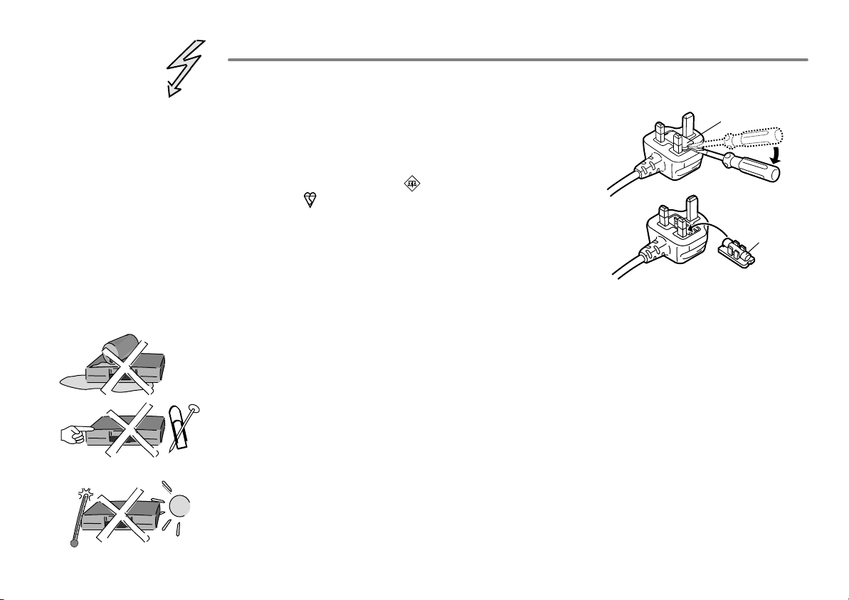
The moulded three pin mains plug is supplied for your safety and convenience and must
NOT be cut off.
!
A 5 amp fuse is fitted in the mains
plug. If the fuse has to be replaced,
it must be of the same rating and
approved by ASTA or BSI to BS1362.
Check for the ASTA mark or the
BSI mark on the body of the fuse.
To replace the fuse, open the fuse
compartment with a screwdriver as
shown and replace the fuse and the
cover securely.
!
To prevent electric shock, do not remove cover. No user serviceable parts inside.
1.Open the fuse
cover with a
screwdriver.
2.Replace the
fuse and close
or attach the
fuse cover.
Refer servicing to qualified service engineer only.
!
WARNING: To reduce the risk of fire, electric shock or product damage, do not expose
this apparatus to rain, moisture, dripping or splashing and that no objects filled with
liquids, such as vases, shall be placed on the apparatus.
!
Do not insert metal object into the slots or openings of the unit.
!
This unit is not disconnected from a.c. mains while it remains connected
to a live mains outlet, even if it has been turned off.
Fuse cover
Fuse
(5 ampere)
!
The socket outlet shall be installed near the equipment and easily accessible or the mains
plug or an appliance coupler shall remain readily operable.
!
This unit is intended for use in moderate climates.
2
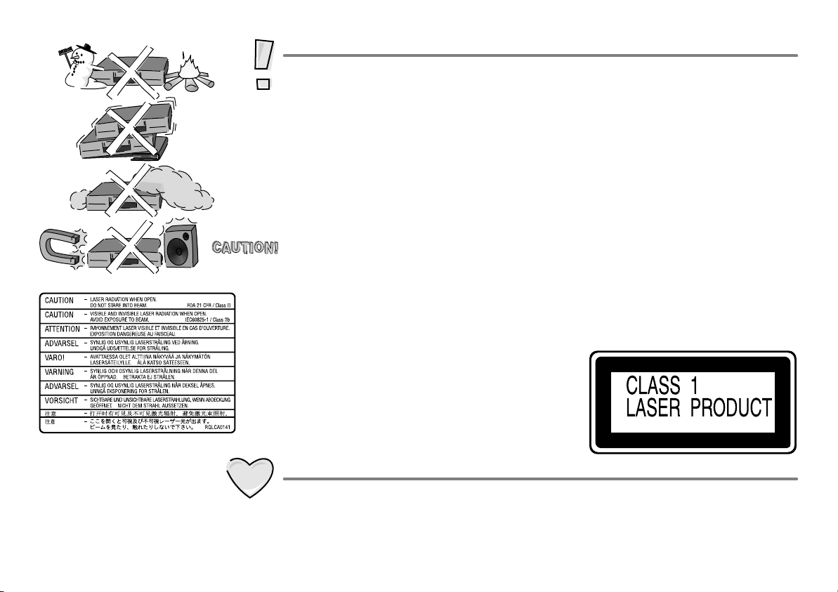
Inside of product
Caution
!
Avoid exposing the unit to direct sunlight or other heat sources.
!
Avoid sudden change in temperature or humidity, dew or condensation may
form, causing malfunction.
!
Dispose of batteries in accordance with the instructions given in this book.
!
Place the unit on a flat, stable surface. Do not place heavy object on top of the unit.
!
Your attention is drawn to the fact that recording of pre-recorded tapes or discs
or other published or broadcast materials may infringe copyright laws.
!
This unit is designed for indoor use only.
!
Do not use in area with strong magnetic fields, e.g. near transmitting antenna.
!
This product may receive radio interference caused by mobile telephones during
use. If such interference is apparent, please increase separation between the
product and the mobile telephone.
!
Do not install or place this unit in a bookcase, built-in cabinet or in another
confined space. Ensure the unit is well ventilated. To prevent risk of electric
shock or fire hazard due to overheating, ensure that curtains and any other
materials do not obstruct the ventilation vents.
!
Do not obstruct the unit’s ventilation openings with newspapers, tablecloths,
curtains, and similar items.
!
Do not place sources of naked flames, such as lighted candles, on the unit.
!
Dispose of batteries in an environmentally friendly manner.
!
This product utilizes a laser. Use of controls or
adjustments or performance of procedures
other than those specified herein may result in
hazardous radiation exposure. Do not open
covers and do not repair yourself.
Refer servicing to qualified personnel.
Care and Maintenance
Back of product, see page 18.
!
The cabinet can be wiped clean with a damp cloth, disconnect from mains before
cleaning. Do not use detergent or solution containing benzol or petroleum.
!
Video heads clogging can occur with use, when this happens picture and sound
will become distorted during playback. Purchase a head cleaning tape or consult
your dealer. Note that video head cleaning is not covered by the warranty.
3
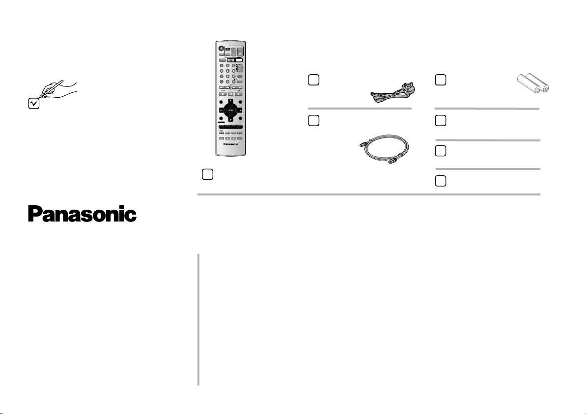
Included Accessories
Check that you have
the accessories and
items shown
Sales and Support Information
VHS/ DVD
AUDIO
VHS/DVD
OUTPUT
CANCEL/RESET
PROG PLAY
DIRECT NAVIGATOR
TOP MENU
DISPLAY
PROG/CHECK
AV ENHANCER
GROUP
TV
AV
VHS
INDEX/SKIP
PAUSE/SLOW
I-TIMER
P. MEMORY
MUSIC WITH
PICTURE
EXT LINKJET REW
ZOOM
VHS/DVD/TV
EUR7720X20
Included
VOLUME
CH
DVD
TRACKING/V-LOCK
ccessories
VIDEO Plus+
INPUT
P
O
REPEAT
SLOW/
SEARCH
FFREW
MENU
PLAY LIST
MENU
EXIT
RETURN
OFF TIMER
REC MODE
PLAY MODE
SETUP
REC
REC CHECK
DUBBING
QUICK REPLAY
A
Remote control
EUR7720X20
AC Mains Lead
RJA0044-3C
RF cable
K2KF2BA00001, VJA0728-A
or K1TWACC00001
Batteries for the
Remote Control
R6 size
Operating Instructions
RQTD0126-B
Quick Start Guide
RQCAD0016
Guarantee Card
Customer Care Centre
!
For UK customers:
08705 357357.
!
For Republic of Ireland customers:
01 289 8333.
!
Visit our website for product
information www.panasonic.co.uk.
!
E-mail:
customer.care@panasonic.co.uk.
4
Direct Sales at Panasonic UK
!
Order accessory and consumable items for your product with ease and
confidence by telephoning our Customer Care Centre
Mon - Friday 9:00am - 5:30pm (Excluding public holidays).
!
Or go on line through our Internet Accessory ordering application at
www.panasonic.co.uk.
!
Most major credit and debit cards accepted.
!
All enquiries, transactions and distribution facilities are provided directly by
Panasonic UK Ltd.
!
It couldn´t be simpler!
!
Also available through our internet is direct shopping for a wide range of
finished products, take a browse on our website for further details.
Remote
!
Some television set models of the
listed manufacturers can not be
operated using this remote
control.
Remote Control - Codes
You may operate television sets with this remote control, by changing its code.
!
Press and hold TV Stand-by.
!
Enter your television set’s two-digit code. If the television set does not operate
correctly, try entering an alternative code.
This set up must be repeated after changing batteries.
Brand Code Brand Code Brand Code Brand Code
Panasonic 01-04,45 GOODMANS 05,06,31 NOKIA 25-27 SANYO 21
AIWA 35 GRUNDIG 09 NORDMENDE 10 SBR 06
AKAI 27,30 HITACHI 22,23,31,40-42 ORION 37 SCHNEIDER 05,06,29-31
BLAUPUNKT 09 INNO HIT 34 PHILIPS 05,06 SELECO 06,25
BRANDT 10,15 IRRADIO 30 PHONOLA 31,33 SHARP 18
BUSH 05,06 ITT 25 PIONEER 38 SIEMENS 09
CURTIS 31 JVC 17,39 PYE 05,06 SINUDYNE 05,06,33
DESMET 05,31,33 LOEWE 07 RADIOLA 05,06 SONY 08
DUAL 05,06 METZ 28,31 SABA 10 TELEFUNKEN 10-14
ELEMIS 31 MITSUBISHI 06,19,20 SALORA 26 THOMSON 44
FERGUSON 10 MIVAR 24 SAMSUNG 31,32,43 TOSHIBA 16
GOLDSTAR/LG 31 NEC 36 SANSUI 05,31,33 WHITE WESTINGHOUSE 05,06
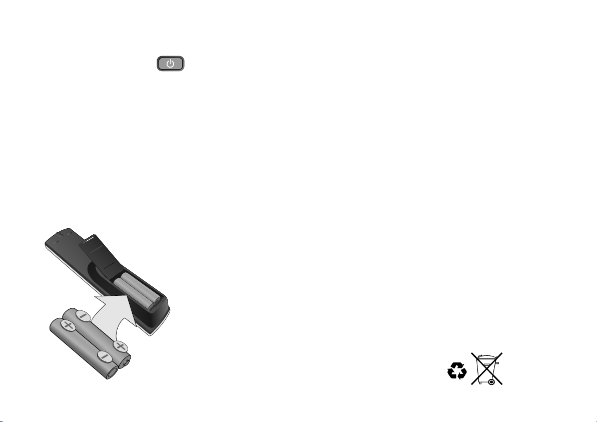
Inserting batteries into the remote control unit:
The batteries last for about a year, depending on how often you use the RC unit.
!
Do not mix old with new batteries or batteries of different types.
!
Only use batteries without any harmful substances (such as lead, cadmium, mercury).
!
Do not use rechargeable type batteries.
!
Remove the batteries if the remote control unit will remain unused for longer
periods of time.
!
Do not heat or short-circuit the batteries.
!
Immediately remove used-up batteries and replace with batteries
of type AA, UM3 or R6.
!
Be sure to put in the batteries the right way round (+and -).
Dispose of batteries, packaging material and the unit
according to statutory regulations. They must not
be thrown into the household refuse.
5
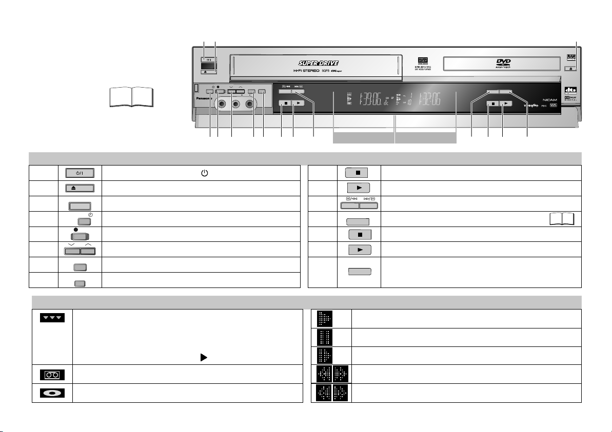
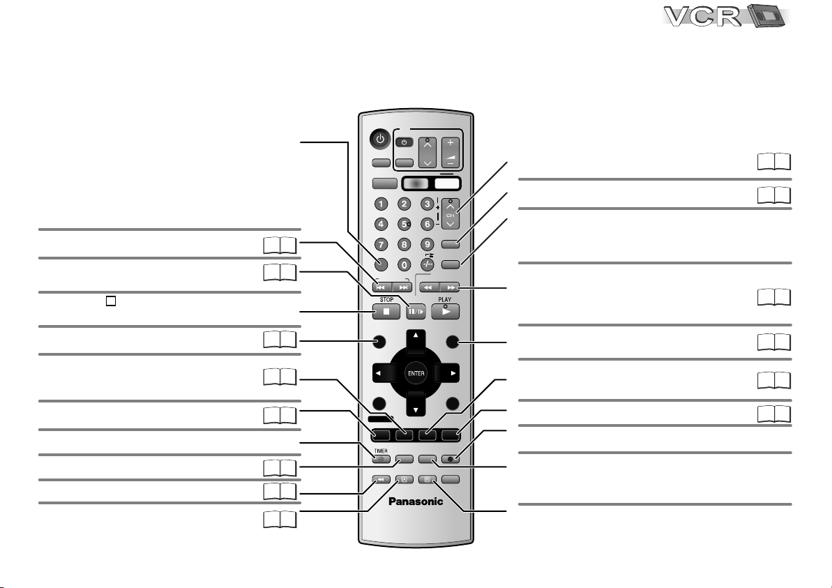
Front Panel
VCR= Video Cassette Recorder
Detailed information
is available on the
specified pages.
Page
1 2
EJECT
TIMER REC
PULL-OPEN
NV-VP31
3
DVD/CD PLAYER
OPEN / CLOSE
REC
VIDEO
QUICK
CH
JET REW
ERASE
AUDIO
R
L/MONO
AV3 IN
NV-VP31
MUSIC WITH PICTURE
AV ENHANCER
2.0 DIGITAL OUT
PAL
4
6 7
5
9 10 11 13 14
8
VCR Display
DVD Display
12
15
Device control
1
2
3
4
5
6
7
8
EJECT
OPEN / CLOSE
TIMER REC
CH
JET REW
QUICK
ERASE
Standby/on switch /I
To eject a video cassette.
Opens and closes the disc tray.
Activates the recording timer.
REC
Record button
Selects a channel.
Fast rewind to the beginning of the tape.
Erases a video cassette.
10
11
12
13
14
15
9
MUSIC WITH PICTURE
AV ENHANCER
VCR Stop button
VCR Playback button
Fast winding / JET SEARCH
MUSIC WITH PICTURE
47
DVD Stop button
DVD Playback button
Automatically optimises and adapts the audio and video
settings to the disc used. The Picture and Audio menus
are not available when this function is enabled.
Display
Active picture signal. The symbol appears on the VCR or
Playback
DVD display. Use the VHS/DVD OUTPUT button to switch
over the picture signal. To directly change the VCR or DVD
output use the VHS, DVD toggle switches in combination
with a function button (e.g. PLAY ).
A video cassette is in.
A disc is in.
Pause playback (still image)
Slow motion
Forward/Backward search
VCR: Fast winding
6
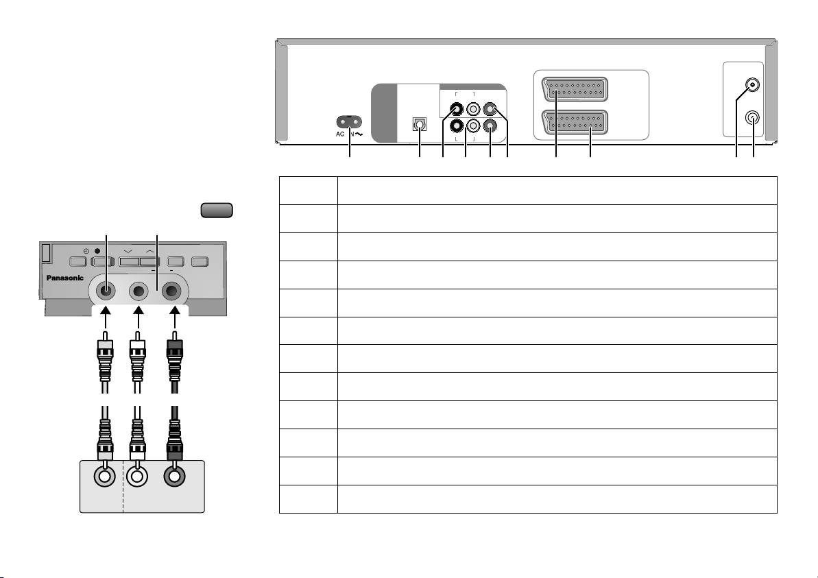
Sockets
Connection to AV3 (front panel)
!
Connect your external unit (e.g. a video
camcorder) with the front panel input.
Just seize the L/Mono port for mono
recording of the audio signal.
!
Use INPUT to select A3.
1211
AUDIO
JET REW
R
NV-VP31
R
QUICK
ERASE
AV3 IN
TIMER REC
PULL-OPEN
NV-VP31
REC
VIDEO
VIDEO
OUT
External equipment
(e.g. Video movie camera)
CH
L/MONO
AudioVideo
L
AUDIO OUT
INPUT
REPEAT
2
3
4
5
6
7
8
9
10
11
12
DIGITAL AUDIO
(PCM/BITSTREAM)
DVD OUT
OPTICAL
1 2 3 4 5 6 7 8 109
1
AC Input socket (Power supply)
DVD Optical Digital Out terminal
VCR/DVD AUDIO OUT socket
DVD AUDIO OUT socket
DVD VIDEO OUT socket
VCR/DVD VIDEO OUT socket
AV1 21-pin Scart socket
AV2 21-pin Scart socket
RF IN socket (Aerial input)
RF OUT socket (Aerial output)
AV3 VIDEO IN socket
AV3 AUDIO IN socket
VCR/DVD OUT
AUDIO
R L
R L
AUDIO
VIDEO
VIDEO
AV 1
(TV)
AV 2
(DECODER/
EXT)
RF IN
RF OUT
L = AUDIO output left channel
R = AUDIO output right channel
L = AUDIO output left channel
R = AUDIO output right channel
L = AUDIO output left channel (Mono)
R = AUDIO output right channel
7
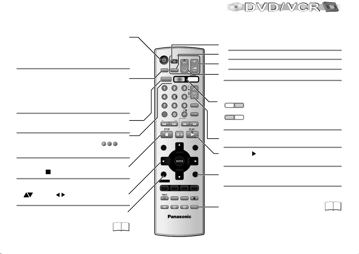
Remote control
General functions
Stand-by/on switch
Press to switch the unit from on to stand-by mode
or vice versa. In stand-by mode, the unit is still
consuming a small amount of power.
Switching this appliance into stand-by mode does
not disconnect it from the mains.
Press the button a couple of times to select
Sound mode.
VCR: stereo (L R), left channel (L -),
right channel (- R), mono (- -) playback
DVD: Select the appropriate audio channel (L R) or
track, which depends on the disc you use
Output signal select button to toggle between
VCR and DVD (for AV1, VCR/DVD OUT)
Numeric keypad
1
Direct input via numeric key pad (18= )
8
CANCEL/RESET: Undoes entries or selections
VHS/ DVD
AUDIO
VHS/DVD
OUTPUT
CANCEL/RESET
INDEX/SKIP
PROG PLAY
DIRECT NAVIGATOR
TOP MENU
TV
AV
VHS
PAUSE/SLOW
CH
SLOW/
SEARCH
VOLUME
DVD
TRACKING/V-LOCK
VIDEO Plus+
INPUT
1O
REPEAT
FFREW
MENU
PLAY LIST
MENU
TV functions
TV set On/Off switch.
TV set AV input selection.
TV set volume control.
To select the respective TV program memory location.
Remote control's VHS/DVD toggle switches to toggle
between VCR and DVD functions
VHS
DVD
VCR functions are enabled.
VHS
DVD
DVD functions (blue labels) are enabled.
Channel selector
Press PLAY to start playback.
To eject cassette or disc
Press STOP for more than 3 seconds.
OSD menu selection buttons.
!
DVD: to select JPEG, WMA or MP3 groups
( ) or titles
!
ENTER: Selects or saves a setting.
VCR:
().
Press the button repeatedly to display
the time, tape counter or remaining tape.
DVD:
To display the DISPLAY menu
8
DISPLAY
EXIT
RETURN
Quits a menu.
PROG/CHECK
AV ENHANCER
GROUP
52
OFF TIMER
I-TIMER
PLAY MODE
P. MEMORY
MUSIC WITH
REC CHECK
PICTURE
EXT LINKJET REW
QUICK REPLAY
ZOOM
VHS/DVD/TV
EUR7720X20
REC MODE
SETUP
REC
DUBBING
To copy a DVD RAM to VHS cassette.
47
Remote control
VCR functions
Tape counter
The tape counter will be automatically reset to
[0:00:00] when you insert a video cassette.
!
Or you can press the CANCEL/RESET button on
the remote control unit to manually reset the tape
counter to [0:00:00].
Finding the start of a recording.
Pause a recording session.
Still or slow motion playback.
Press STOP to stop recording,
playing back or winding.
Plays back programmed recordings.
Defines programmes transmitted to
the same program memory location
at the same time.
To display the Timer recording menu.
Activates the recording timer.
MUSIC WITH PICTURE
47
For fast rewinding to the beginning of the tape.
To record using the external recording
level control.
A: To delete tagged station.
VHS/ DVD
TV
VOLUME
AUDIO
VHS/DVD
OUTPUT
CH
AV
VHS
DVD
TRACKING/V-LOCK
Tracking control of disturbed
images during playback
Video Plus+ menu
23
30
AV input select button
PAUSE/SLOW
VIDEO Plus+
1O
SLOW/
SEARCH
INPUT
REPEAT
FFREW
24
22
CANCEL/RESET
INDEX/SKIP
Pressing the INPUT button a couple of times will
select A1, A2, A3 (front) or dc (DVD internal).
Goes from Stop into Fast Forward or Fast
Rewind mode. Forward and backward search
24
during playback.
OFF TIMER
PLAY MODE
REC CHECK
QUICK REPLAY
MENU
PLAY LIST
MENU
EXIT
RETURN
REC MODE
SETUP
REC
DUBBING
Displays the VCR menu.
Switches the unit into stand-by mode
after the set time.
Sets the tape speed.
Video recording
You will be displayed either the Timer recording
menu or an information on the current recording.
Toggles between TV reception and video
playback channel.
21
24
26
PROG PLAY
28
29
28
24
32
DIRECT NAVIGATOR
TOP MENU
DISPLAY
PROG/CHECK
AV ENHANCER
GROUP
I-TIMER
P. MEMORY
MUSIC WITH
PICTURE
EXT LINKJET REW
ZOOM
VHS/DVD/TV
EUR7720X20
B: Move tagged station.
9
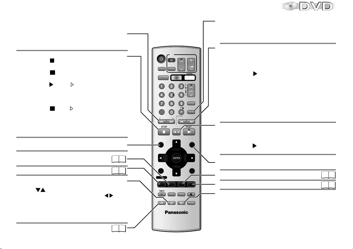
Remote control
DVD functions
Skip chapters, titles or frames
!
Press SKIP during playback or in pause mode.
Stop playback
!
Press STOP twice.
Resume
!
Press STOP during playback
to store the current position on the disc.
!
Press PLAY while [ ] is flashing on the
display. Playback will be resumed at the point
where you stopped it.
Cancel the Resume function
!
Press STOP until [ ] is disappears from
the display.
D
Opening the disc tray or the unit going into
stand-by mode also clears the stored position
on the disc.
Displays the DVD-RAM menu.
Displays the main menu.
Resumes playback at stored position
following an interruption.
AV ENHANCER
Zoom
!
Press ZOOM during playback.
Press to set the zoom factor,
to select a Zoom mode: ENTER plus .
Restore factory setting
!
Press ZOOM until x1.00 is shown.
The zoom functionality may be restricted
depending on the disc format.
Group Search
10
For some disc formats
not all of the described
DVD functions are
available.
VHS/ DVD
TV
VOLUME
AV
PAUSE/SLOW
I-TIMER
P. MEMORY
MUSIC WITH
PICTURE
EXT LINKJET REW
ZOOM
VHS
CH
OFF TIMER
PLAY MODE
REC CHECK
QUICK REPLAY
DVD
TRACKING/V-LOCK
VIDEO Plus+
INPUT
1O
REPEAT
SLOW/
SEARCH
MENU
PLAY LIST
MENU
EXIT
RETURN
REC MODE
SETUP
REC
DUBBING
FFREW
AUDIO
VHS/DVD
OUTPUT
CANCEL/RESET
INDEX/SKIP
PROG PLAY
DIRECT NAVIGATOR
TOP MENU
43
53
DISPLAY
PROG/CHECK
AV ENHANCER
GROUP
Repeat
!
Press REPEAT during playback.
There is no mode for repeatedly playing back
entire discs.
Slow motion (backwards/forwards)
!
Press SLOW in Pause mode.
Keeping the button pressed increases the speed of
search at 5 steps.
!
Press PLAY to resume normal playback.
D
VCDs do not support reverse slow motion playback.
Search
!
Press SEARCH during playback.
Keeping the button pressed increases the speed
of search at 5 steps.
Pause playback (still image)
!
Press PAUSE during playback.
Playback stops at the current picture frame.
!
Press PLAY to resume playback.
Displays a Playlist
Displays the menu.
Random playback/Program play
Displays the SETUP menu.
Scene replay
!
Press QUICK REPLAY during playback.
Every push of the button replays a couple of
44 45
54
seconds of the current track or programme.
VHS/DVD/TV
EUR7720X20
52
However, you cannot go back to before the
beginning of a title.
D
QUICK REPLAY is not supported by all discs.
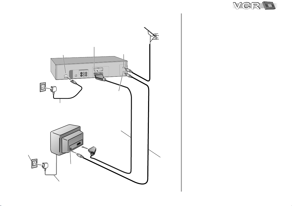
Connecting with 21-pin Scart cable (Fully wired)
AC mains socket
1
AC IN~
AC IN
5
5
AC mains lead
VCR / DVD
L
T A U
I
G
I
D
T
B S A
M/
C
P I
(
T
U
O
D
V
D
I
T
P
O
AC mains lead
TV
Aerial input
AV1
21-pin Scart socket
T
O
V
/D
RDU
C
V
O
E
D
I
V
I O
D
U
A
L
R
O
I
D
A
)
M
R
T E
L
R
O
E
D
I
V
O
D
U
A I
L
A
C
RF IN
Aerial input
1
V
A
)
V
T
(
2
AV
R/
E
D
O
C
E
D
(
)
T
X
E
RF OUT
Aerial output
21-pin Scart cable
4
Aerial
2
Follow the steps described below.
Ensure TV Power is disconnected
1
from AC Mains socket.
N
R
I
F
U
O
T
F
R
Connect aerial to the RF IN (Aerial
2
input) connector of the VCR/DVD.
Connect the VCR/DVD´s RF OUT
3
(Aerial output) to the TV set’s
Aerial in connector.
Connect the VCR/DVD’s AV1 socket
4
(21-pin Scart socket) to the TV set’s
Scart In socket.
Connect VCR/DVD and TV set to
5
RF coaxial cable
3
the AC mains socket.
Follow the steps for VCR Auto Setup
on page 13.
11
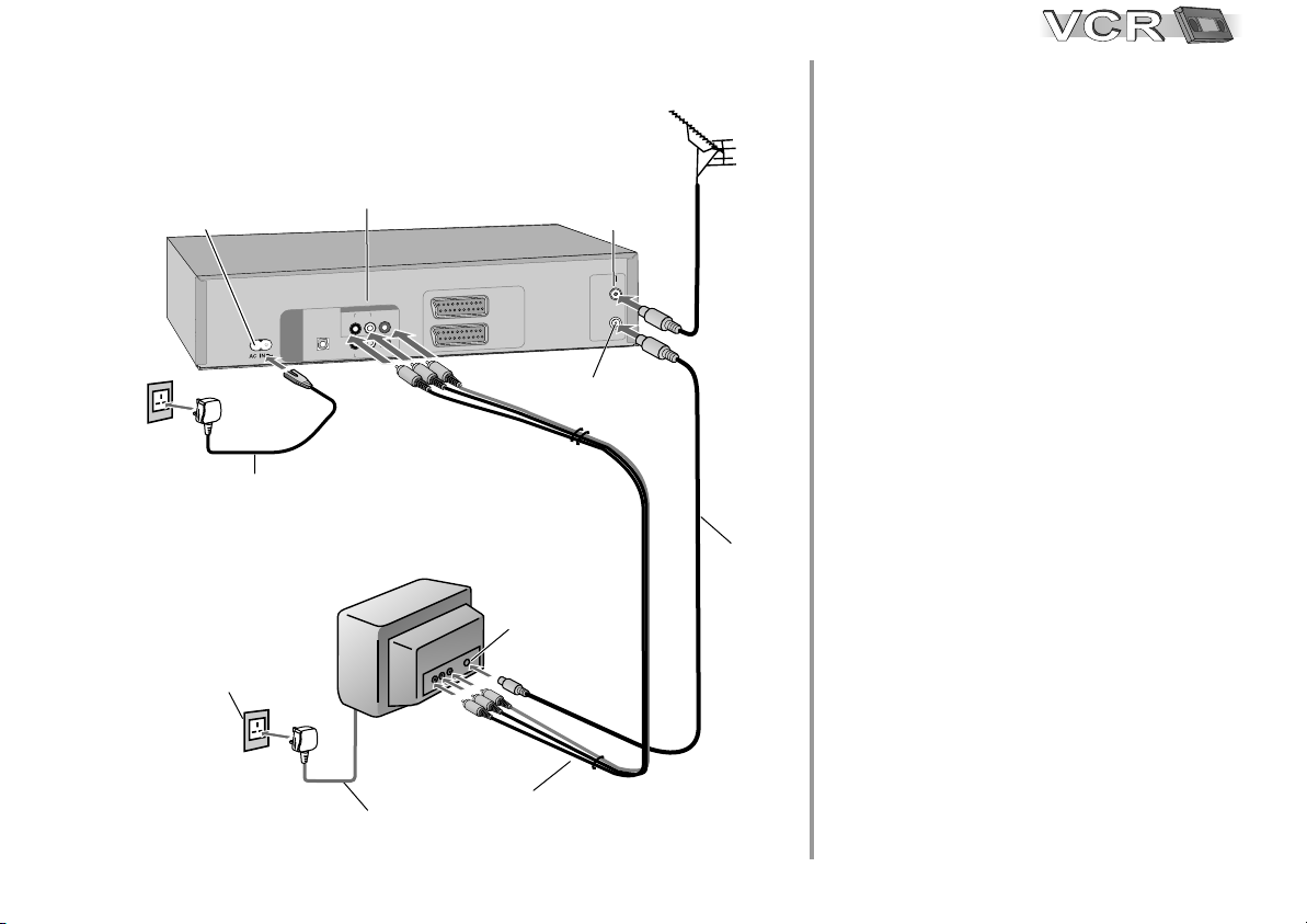
Connecting with Audio-Videocable
AUDIO (R/L) / VIDEO
Audio / Videooutput
AC IN~
5
AC mains socket
1
AC mains lead
AC IN
VCR/DVD
1
AV
)
V
T
O
D
V U T
D
/
C
V R
ED OV
I
O
I
U
A D
L
R
O
I
U
A
GT L A D
DI I
)
M
E
T A
S
I
B
/
M
C T R
P
(
T
U
O
V
DD
L
R
O
E
D
I
V
O
D I
U
A
A
CL
I
T
P
O
TV
(
2
V
A
/
R
DE
CO(
E
D
)
T
X
E
Aerial input
RF OUT
Aerial
RF IN
Aerial
N
I
F
R
OU
T
F
R
output
input
RF coaxial
3
cable
Aerial
2
Follow the steps described below.
Ensure TV Power is disconnected
1
from AC Mains socket.
Connect aerial to the RF IN (Aerial
2
input) connector of the VCR/DVD.
Connect the VCR/DVD´s RF OUT
3
(Aerial output) to the TV set’s
Aerial in connector.
4
Connect the VCR/DVD OUT
(AUDIO R/L, VIDEO) sockets of the
VCR/DVD to the TV input.
Connect VCR/DVD and TV set to
5
the AC mains socket.
12
5 AC mains lead
4
Audio (L/R) / Videocable
Follow the steps for VCR Auto Setup
on page 13.
Auto Setup
Tuning : Ch 21
EXIT
: exit
Owner ID
PIN number :
Name :
House No :
Postcode :
You now have the opportunity
help the police crack crime
:select : store
MENU EXIT
: return : exit
Datum / ZeitClock set
MANUAL
Time : 12 : 00 : 00
Date : 11. 6. 04
****
**************
***********
***********
to enter your details and
see instruction book.
ENTER
VCR Auto Setup with 21-pin Scart cable / Audio-Videocable
(Automatic tuning)
!
Turn on your television set.
!
With the Stand-by/on switch turn on the VCR/DVD.
Automatic tuning for all available TV stations begins.
Approximate duration is 5 minutes.
!
After Automatic tuning has finished, press EXIT.
The Owner ID screen will appear.
VCR Display
Owner ID
You can complete the Owner ID now or skip this step and do it later. To do it
later, press the EXIT button. Your VCR is now ready to use. Optionally, you can
have a QUICK SETUP following VCR Auto Setup for the DVD player (page 40).
!
To set the Owner ID now, press the Numeric buttons or to enter a fourdigit PIN number.
!
Press , to correct the digit.
!
Make sure that you will remember the PIN number (make a note of it).
!
Press the ENTER button twice to confirm.
!
Enter the [Name], [House No] and [Postcode] in the same way.
!
Press the ENTER button to confirm each entry.
!
Press the EXIT button to leave the Owner ID screen.
!
You will now see the TV picture. Your VCR/DVD is now ready to use.
Optionally, you can have a QUICK SETUP following VCR Auto Setup for the
DVD player (page 40).
If the clock setting menu appears
(Auto clock set was not possible due to a weak signal)
!
Press to set the correct time and date.
!
Press the ENTER button to finish this setting.
D
Mind that a wrong date or time will influence the programmed recording of TV
programmes (don't forget to change summer time and winter time).
D
If Auto Setup has previously been completed the VCR will not start Auto Setup
automatically. In this case you can re-start Auto Setup again. See page 35.
D
If you want to cancel Auto Setup before it has finished, press the EXIT button.
You can restart Auto Setup again. See page 35.
13
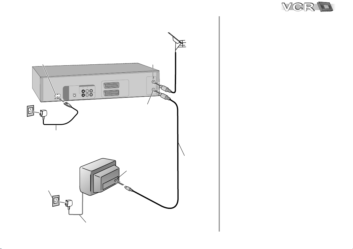
Connecting with RF cable
You can connect the VCR/DVD to your
TV set by using a RF cable.
AC IN~
4
AC mains socket
1
AC mains lead
AC IN
VCR/DVD
O
U
D
V
D
/
C T
VR
E
D O
I
V
O
IA
D
U
L
R
O
IG
U
A D
L
A
T
I I
D
)
M
E
T A
IT R
B
/
M S
C
P
(
UT
O
D
V
D
L
R
O
E
D
I
V
O
I
D
U
A
L
A
I
T
P
O C
TV
1
V
A
)
V
T
(
2
V
A
R/
E
D
O
DE
( C
T
X )
E
Aerial input
RF OUT
Aerial
RF IN
Aerial
N
I
F
R
OU
F
R
output
T
input
Aerial
2
RF coaxial cable
3
Follow the steps described below.
Ensure TV Power is disconnected
1
from AC Mains socket.
Connect aerial to the RF IN (Aerial
2
input) connector of the VCR/DVD.
Connect the VCR/DVD´s RF OUT
3
(Aerial output) to the TV set’s
Aerial in connector.
Connect VCR/DVD and TV set to
4
the AC mains socket.
14
Follow the steps for VCR Auto Setup
on page 15.
4 AC mains lead
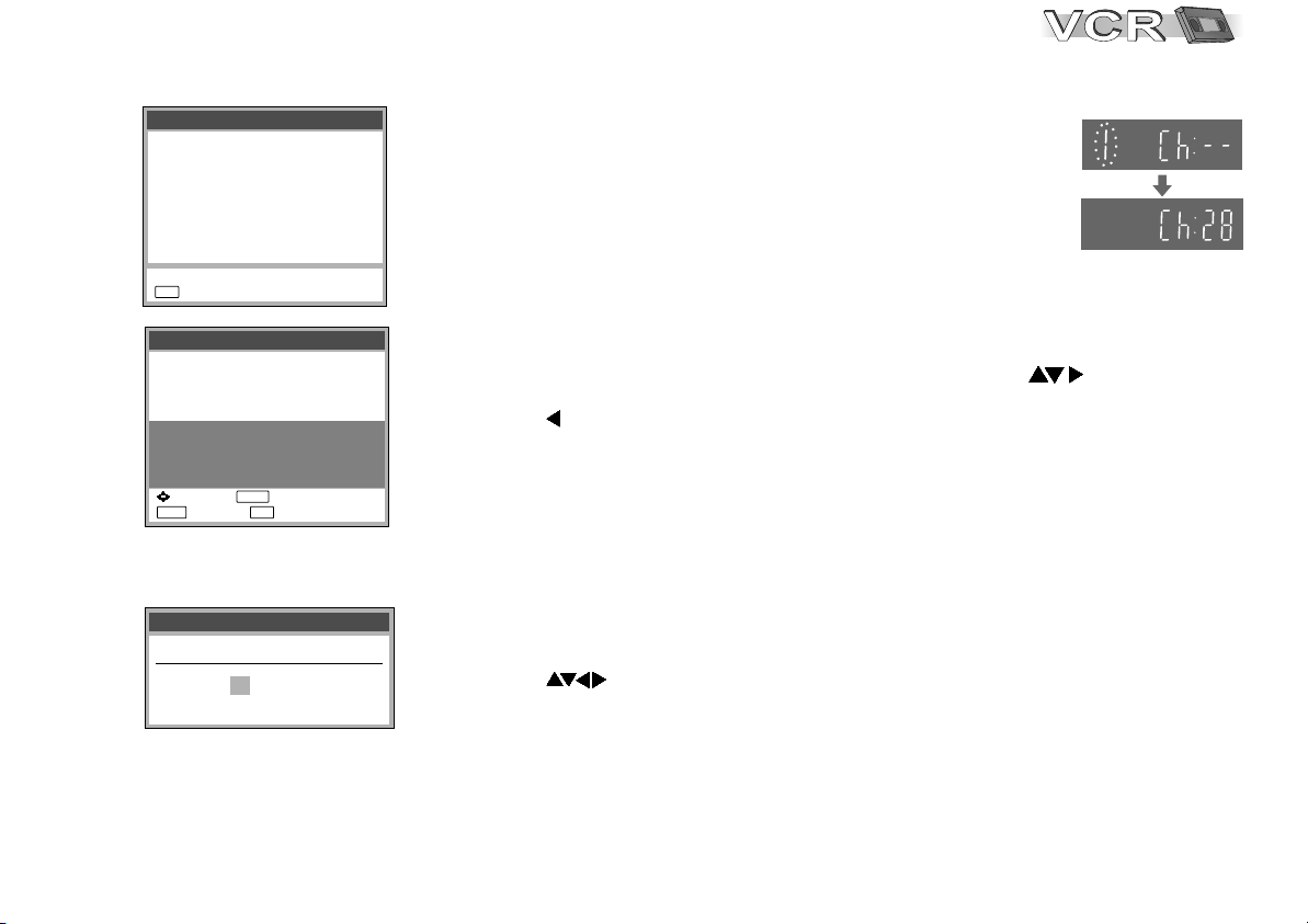
VCR Display
Auto Setup
Tuning : Ch 21
EXIT
: exit
Owner ID
PIN number :
Name :
House No :
Postcode :
You now have the opportunity
help the police crack crime
:select : store
MENU EXIT
: return : exit
Datum / ZeitClock set
MANUAL
Time : 12 : 00 : 00
Date : 11. 6. 04
****
**************
***********
***********
to enter your details and
see instruction book.
ENTER
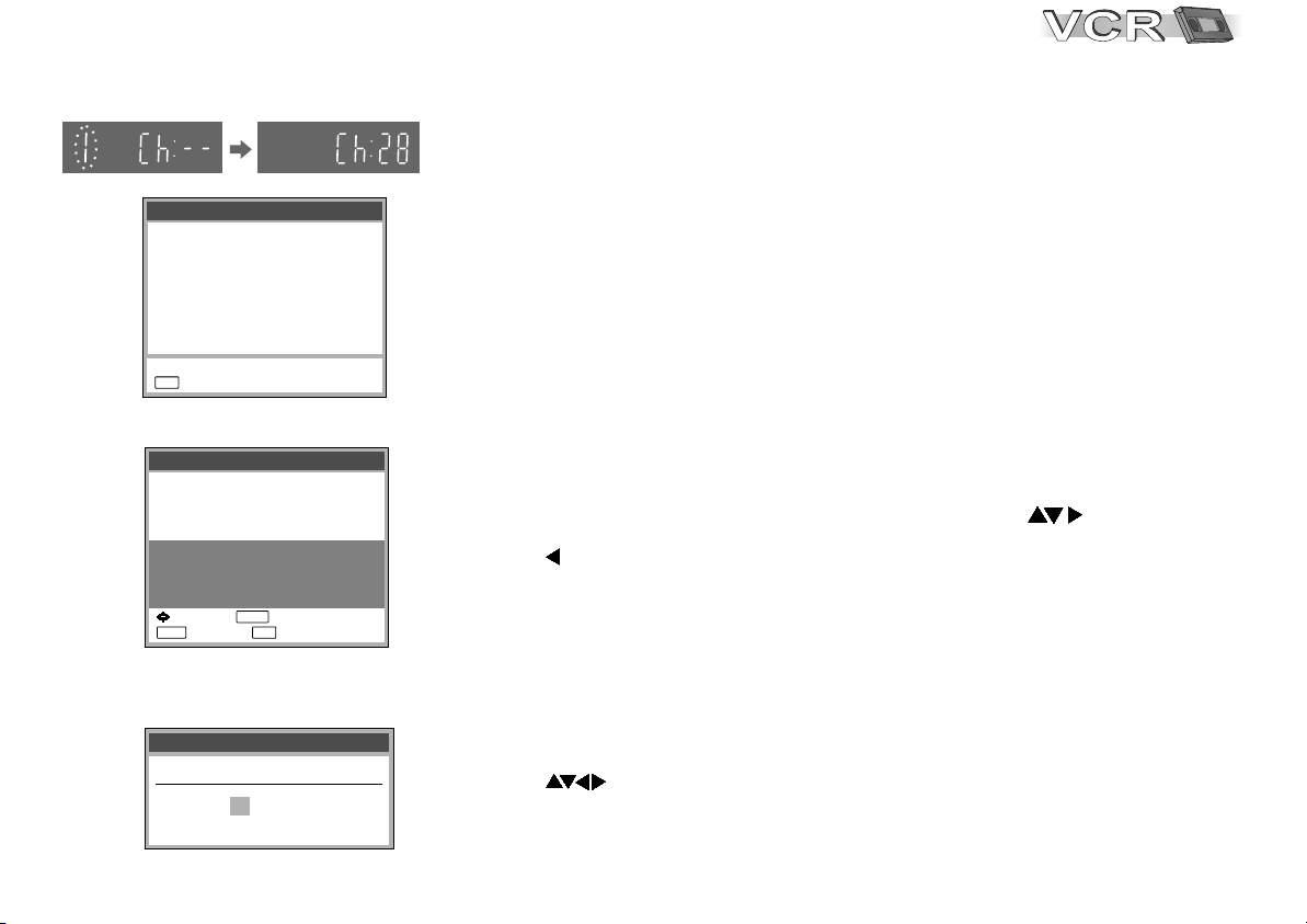
VCR Auto Setup with RF cable (Automatic tuning)
!
Turn on your television set.
!
With the Stand-by/on switch turn on the VCR/DVD. Automatic tuning for all
available TV stations begins. Approximate duration is 5 minutes.
!
After Automatic tuning has finished, press EXIT. The Owner ID screen will appear.
- While Auto Setup is running the first digit of the VCR display will flash. After a
while it will stop flashing and the RF output channel number will be displayed.
- Select an unused channel pre-set on your TV and tune it to the RF output
channel number shown on the VCR display (or until you can clearly see the
Auto Setup screen). Store the new video playback channel (refer to the
instructions for your TV).
D
In some cases, the RF output channel may interfere with the TV stations
transmitted in your area. This may prevent you from seeing the On-Screen
Display clearly. Please see page 20 for removing the interference before
restarting Auto Setup (page 35).
Owner ID
You can complete the Owner ID now or skip this step and do it later. To do it
later, press the EXIT button. Your VCR is now ready to use. Optionally, you can
have a QUICK SETUP following VCR Auto Setup for the DVD player (page 40).
!
To set the Owner ID now, press the Numeric buttons or to enter a fourdigit PIN number.
!
Press to correct the digit.
!
Make sure that you will remember the PIN number (make a note of it).
!
Press the ENTER button twice to confirm.
!
Enter the [Name], [House No] and [Postcode] in the same way.
!
Press the ENTER button to confirm each entry.
!
Press the EXIT button to leave the Owner ID screen.
!
You will now see the TV picture. Your VCR is now ready to use. Optionally, you can
have a QUICK SETUP following VCR Auto Setup for the DVD player (page 40).
If the clock setting menu appears
(Auto clock set was not possible due to a weak signal)
!
Press to set the correct time and date.
!
Press the ENTER button to finish this setting.
D
Mind that a wrong date or time will influence the programmed recording of TV
programmes (don't forget to change summer time and winter time).
15
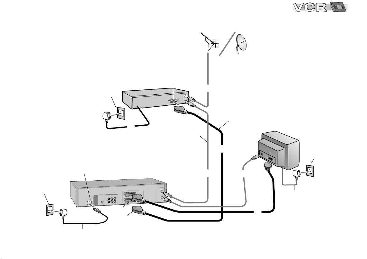
Connecting to Satellite Receiver, Set Top Box
Connecting to Satellite Receiver, Set Top Box
You can connect a Set Top Box to receive digital broadcast
You can connect a Set Top Box to receive digital broadcast
by aerial (DVB-T) signals, a satellite receiver
by aerial (DVB-T) signals, a satellite receiver
(digital/analogue) or a decoder to decrypt encrypted
(digital/analogue) or a decoder to decrypt encrypted
programmes.
programmes.
Aerial
16
16
1
AC mains socket
AC mains socket
1
AC IN~
U
D
V
D OT
4
AC mains lead
(supplied)
External unit
To AC Mains socket
VCR / DVD
T
U
D
V
/D
R
C
V O
E
D
I
VO
D
U
A I O
L
R
O
I
A
L
A U
T
I
IG D
D
)
M
A
E
R
T
S
T
I
B
/
M
C
P
(
L
R
O
E
D
I
V
O
I
D
U
A
L
A
C
TI
P
O
(AV1)
(AV2)
21-pin Scart socket
3
21-pin Scart cable
4
RF cable
(supplied)
2
3
N
FI
1
A V
)
V
T
(
2
V
A
CO
E
D
(
T
E
R
T
U
O
F
R
/
R
DE
)X
3
2
TV
AC mains lead
4
AC mains socket
1

Follow the steps described below.
Ensure TV Power, External unit Power and VCR/DVD Power are disconnected
1
from AC Mains socket.
2
Connect a 21-pin scart cable (fully wired) to the AV2 21-pin scart socket on the
VCR/DVD and to the 21-pin scart socket on the External unit.
Connect a 21-pin scart cable (fully wired) to the AV1 21-pin scart socket on the
VCR/DVD and to the 21-pin scart socket on the TV set.
Connect aerial to the Aerial in connector of the External unit.
3
Connect the External unit´s Aerial out connector to the VCR/DVD’s RF IN (Aerial input).
Connect the VCR/DVD´s RF OUT (Aerial output) to the TV set’s Aerial in connector.
4
Connect the External unit, VCR/DVD and TV set to the AC mains supply.
Switch on the TV set and VCR/DVD.
5
Set the VCR menu settings for AV2 according the connected External unit (See page 32).
Switch on the External unit. Then follow page 13 for VCR Auto Setup with 21-pin
6
Scart cable.
D
[RGB] means separate Red/Green/Blue colour signals. If you connect a TV equipped with RGB input
capability to the AV1 socket on this VCR/DVD, and a decoder equipped with RGB output capability to
the AV2 socket, RGB signals will pass through the VCR/DVD to the TV when the VCR/DVD is in
stand-by mode. The RGB signals cannot be recorded or produced by this VCR/DVD.
17

DVD-Connectors
Before connecting
!
Verify that all devices to be connected
up are unplugged from the AC mains.
DVD OUT
Optical digital
audio cable
Digital connectors (OPTICAL)
To play programmes with a 5.1-channel surround sound,
connect the digital audio output ( OPTICAL ) with an
external Multi-channel Dolby Digital Decoder, for example.
Prerequisites for making recordings with an external digital recorder
- The original disc must not be copy-protected.
- The recorder must be able to process signals with a scanning
frequency of 48 kHz/16 bit.
- You cannot make MP3/WMA recordings.
D
Adapt the Audio SETUP menu settings to the following:
PCM Digital Output: [up to 48 kHz]
Dolby Digital / DTS Digital Surround / MPEG: [PCM]
D
Deactivate function Advanced Surround.
Push in the jack all the way into the
socket with this side facing up.
OPTICAL
Amplifier (example)
55
53
DIGITAL AUDIO
(PCM/BITSTREAM)
OPTICAL
RF IN
RF OUT
Red
VCR/DVD OUT
AUDIO
R L
R L
AUDIO
VIDEO
VIDEO
AV 1
(TV)
AV 2
(DECODER/
EXT)
YellowWhite
DVD ports
Connection to a TV set without a scart
socket or to an amplifier component
AUDIO IN
VIDEO
IN
R L
Amplifier or
TV set (example)
To be able to hear sound in stereo or Dolby Pro Logic quality,
attach an amplifier or an analogue audio component supporting
these features.
To avoid sound quality problems deactivate function
Advanced Surround when you attach an amplifier with
Dolby Pro Logic functionality.
(home cinema):
53
18
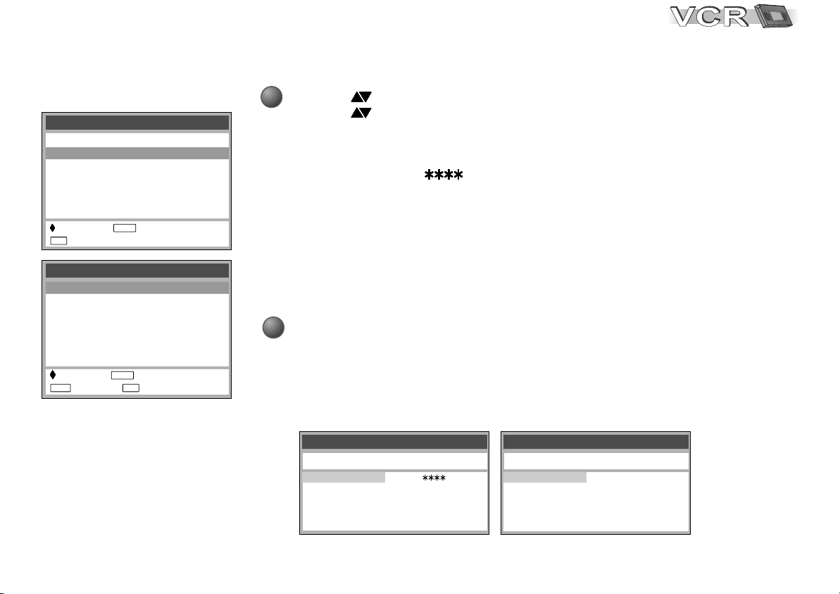
Checking the Settings
after Auto Setup
Menu
Timer recording
Tuning
Clock set
Others
:select : access
EXIT
: exit
Tuning
Manual
Auto Setup
Shipping condition
Owner ID
: select : access
MENU EXIT
: return : exit
ENTER
ENTER
MENU
PLAY LIST
MENU
EXIT
RETURN
!
Press the MENU button to display the OSD Main menu on the TV screen.
!
Press to select Tuning then press the ENTER button.
!
Press to select Manual then press the ENTER button to display the list of
tuned TV stations and confirm that all available TV stations have been set
correctly.
D
If station name is [ ]:
The asterisks indicate that a station was found during Auto Setup but has not
been named (due to weak signal).
The stations in the list with asterisk will need to be named manually see page 34.
D
If station name is [- - - -]:
The dashes represent unused channel positions.
The stations in the list with dashes will need to be set manually. See page 33.
!
Press the EXIT button to exit the On Screen Display.
When the station names and/or channel numbers have not been set correctly,
see page 34 for details.
When no station has been found, confirm all connections of the VCR again and
restart the Auto Setup. See page 35 for details.
TV Reception Channels
Tuning
Pos Name Ch Pos Name Ch
1 BBC1 22
2 BBC2 23
3 ITV 24
4 CH4 25
5 CH5 26
Example of UK model Example of Ireland model
6 30
7 - - - - - - 8 - - - - - - 9 - - - - - - 10 - - - - - - -
Tuning
Pos Name Ch Pos Name Ch
1 RTE1 2
2 NET2 4
3 TNG 6
4 BBC1 22
5 BBC2 23
6 ITV 24
7 CH4 25
8 CH5 26
9 - - - - - - 10 - - - - - - -
The reception
channels are
different for UK
and Ireland.
19
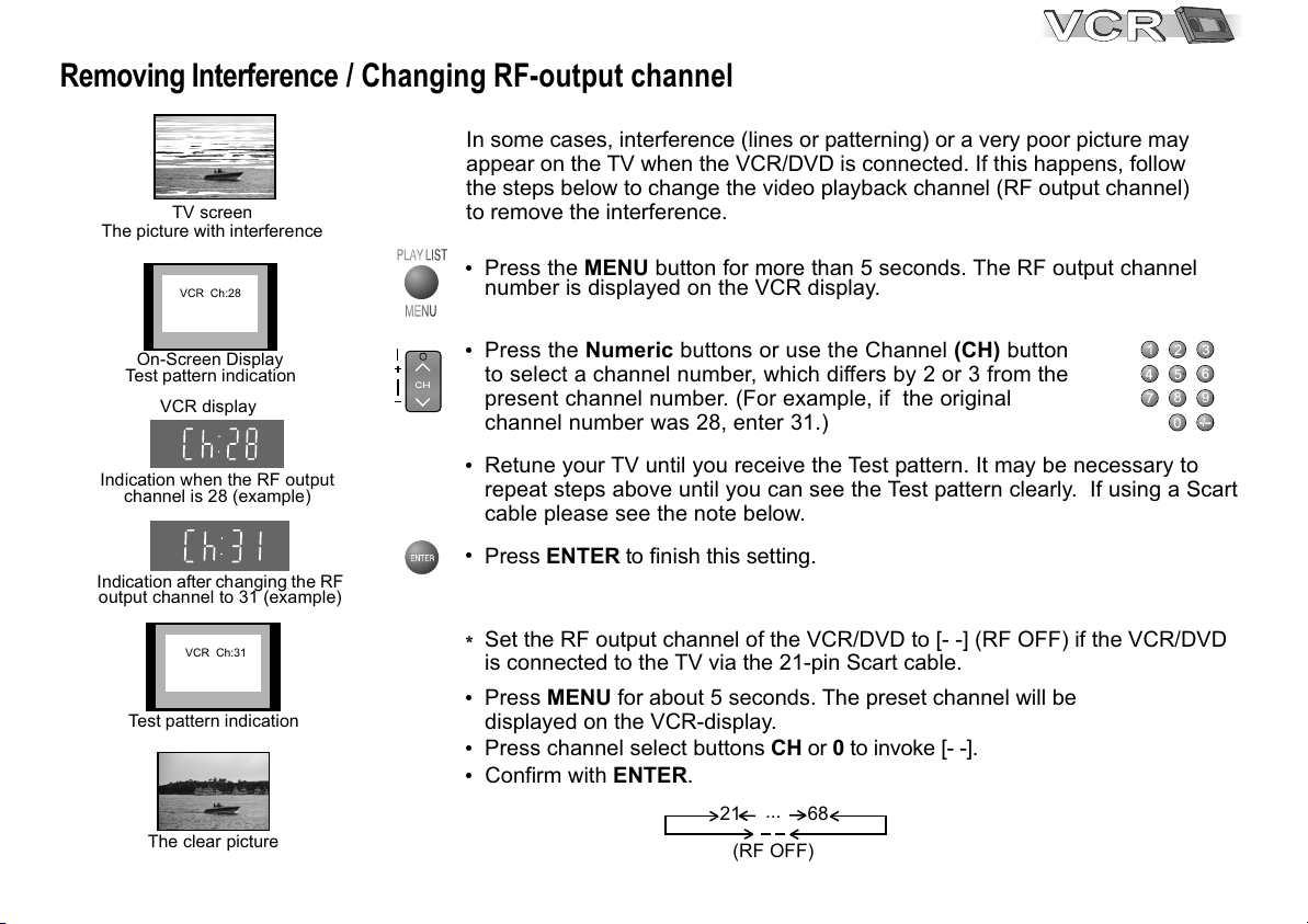
Removing Interference / Changing RF-output channel
In some cases, interference (lines or patterning) or a very poor picture may
appear on the TV when the VCR/DVD is connected. If this happens, follow
the steps below to change the video playback channel (RF output channel)
The picture with interference
Indication when the RF output
Indication after changing the RF
output channel to 31 (example)
TV screen
VCR Ch:28
On-Screen Display
Test pattern indication
VCR display
channel is 28 (example)
VCR Ch:31
Test pattern indication
The clear picture
20
PLAY LISTPLAY LIST
TRACKING/V-LOCK
to remove the interference.
MENU
!
Press the MENU button for more than 5 seconds. The RF output channel
number is displayed on the VCR display.
MENUMENU
!
Press the Numeric buttons or use the Channel (CH) button
to select a channel number, which differs by 2 or 3 from the
present channel number. (For example, if the original
channel number was 28, enter 31.)
!
Retune your TV until you receive the Test pattern. It may be necessary to
repeat steps above until you can see the Test pattern clearly. If using a Scart
cable please see the note below.
!
Press ENTER to finish this setting.
D
Set the RF output channel of the VCR/DVD to [- -] (RF OFF) if the VCR/DVD
is connected to the TV via the 21-pin Scart cable.
!
Press MENU for about 5 seconds. The preset channel will be
displayed on the VCR-display.
!
Press channel select buttons CH or 0 to invoke [- -].
!
Confirm with ENTER.
...
21
(RF OFF)
8 9
68
 Loading...