

Panasonic KX-FT57E Service manual
ORDER NO. KM79905280C2
KX-FT57E
INTRODUCTION
PERSONAL FACSIMILE
KX-FT57E
(for United Kingdom)
WARNING
This service information is designed for experienced repair technicians only and is not designed for use by the general public.
It does not contain warnings or cautions to advise non-technical individuals of potential dangers in attempting to service a product.
Products powered by electricity should be serviced or repaired only by experienced professional technicians.
Any attempt to service or repair the product or products dealt with in this service information by anyone else could result in serious
injury or death.
C
1999 Kyushu Matsushita Electric Co., Ltd.
All rights reserved. Unauthorized copying and distribution is a violation of law.
|1 |

KX-FT57E
The serial number contents of 11 digits. The serial number may be found on the bottom of the unit.
INTRODUCTION
TABLE OF CONTENTS
Page
SAFETY PRECAUTIONS.......................................................................................................................................5
INSULATION RESISTANCE TEST ........................................................................................................................5
FOR SERVICE TECHNICIANS ..............................................................................................................................5
BATTERY CAUTION ..............................................................................................................................................6
FITTING CAUTION.................................................................................................................................................6
AC CAUTION..........................................................................................................................................................7
PERSONAL SAFETY PRECAUTIONS ..................................................................................................................8
SPECIFICATIONS..................................................................................................................................................9
CCITT NO.1 TEST CHART ..................................................................................................................................10
LOCATION OF CONTROLS ................................................................................................................................11
FEATURES...........................................................................................................................................................12
CONNECTION......................................................................................................................................................13
INSTALLATION ..............................................................................................................................................14~17
COMPONENT LOCATIONS.................................................................................................................................18
MAINTENANCE ITEMS..................................................................................................................................18, 19
CLEANING THE INSIDE OF THE UNIT...............................................................................................................20
TROUBLESHOOTING GUIDE
TROUBLESHOOTING SUMMARY ......................................................................................................................22
USER RECEIVERABLE ERRORS.......................................................................................................................23
TROUBLESHOOTING DETAILS................................................................................................................... 24~91
PROGRAMMING AND LISTS ....................................................................................................................... 92~97
TEST FUNCTIONS.........................................................................................................................................98, 99
ADJUSTMENTS
TABLE OF TEST EQUIPMENTS AND TOOLS ................................................................................................101
ADJUSTING THE FEEDER PRESSURE...........................................................................................................101
CCD ADJUSTMENTS ............................................................................................................................... 102~104
DOCUMENT READ START POSITION ADJUSTMENT............................................................................104, 105
|2 |

DISASSEMBLY INSTRUCTIONS
DISASSEMBLY INSTRUCTIONS ............................................................................................................. 108~116
HOW TO REPLACE THE FLAT PACKAGE IC ..................................................................................................117
CIRCUIT OPERATIONS
CONNECTION DIAGRAM..................................................................................................................................119
GENERAL BLOCK DIAGRAM ...................................................................................................................120, 121
CONTROL SECTION ................................................................................................................................ 122~127
FACSIMILE SECTION............................................................................................................................... 127~135
DIGITAL SPEAKER PHONE CIRCUIT ..............................................................................................................136
MODEM SECTION .................................................................................................................................... 137~143
EXPLANATION OF ANALOG SECTION BLOCK DIAGRAM.....................................................................144, 145
NCU SECTION ...........................................................................................................................................146~149
KX-FT57E
INTRODUCTION
ANALOG GATE ARRAY.............................................................................................................................150, 151
OPERATION PANEL..........................................................................................................................................152
LCD COG TYPE .................................................................................................................................................153
POWER SUPPLY BOARD SWITCHING SECTION...................................................................................154~156
FOR THE SCHEMATIC DIAGRAMS..................................................................................................................157
PRINTED CIRCUIT BOARD (DIGITAL BOARD) ................................................................................................159, 160
SCHEMATIC DIAGRAM (DIGITAL CIRCUIT).............................................................................................................161
SCHEMATIC DIAGRAM (ANALOG CIRCUIT)............................................................................................................162
PRINTED CIRCUIT BOARD (ANALOG BOARD) ...............................................................................................163, 164
SCHEMATIC DIAGRAM (CCD)...................................................................................................................................165
PRINTED CIRCUIT BOARD (CCD) ............................................................................................................................165
PRINTED CIRCUIT BOARD (SWITCHING POWER SUPPLY BOARD) ....................................................................166
SCHEMATIC DIAGRAM (SWITCHING POWER SUPPLY CIRCUIT) ........................................................................167
PRINTED CIRCUIT BOARD (OPERATION PANEL BOARD) ....................................................................................168
SCHEMATIC DIAGRAM (OPERATION PANEL CIRCUIT).........................................................................................169
TERMINAL GUIDE OF IC'S TRANSISTOR AND DIODES .........................................................................................170
TOOLS........................................................................................................................................................................ 171
CABINET, MECHANICAL AND ELECTRICAL PARTS LOCATION ...................................................................172~177
ACCESSORIES AND PACKING MATERIALS............................................................................................................178
REPLACEMENT PARTS LIST ........................................................................................................................... 179~189
|3 |

KX-FT57E
INTRODUCTION
Page
Safety Precautions ................................................................................... 5
Insulation Resistance Test ....................................................................... 5
For Service Technicians........................................................................... 5
Battery Caution......................................................................................... 6
Fitting a Plag to the Mains Lead............................................................... 6
AC Caution ............................................................................................... 7
Personal Safety Precautions .................................................................... 8
Specifications ........................................................................................... 9
ITU-T Test Chart No. 1........................................................................... 10
Location of Controls ............................................................................... 11
Features ................................................................................................. 12
Connection ............................................................................................. 13
Installation ........................................................................................ 14~17
Component Locations ............................................................................ 18
Maintenance Items ........................................................................... 18, 19
Cleaning the Inside of the Unit ............................................................... 20
|4 |
KX-FT57E
SAFETY PRECAUTIONS
1. Before servicing, unplug the power cord to prevent an electric shock.
2. When replacing parts, use only the manufacturer’s recommended components.
3. Check the condition of the power cord. Replace if wear or damage is evident.
4. After servicing, be sure to restore the lead dress, insulation barriers, insulation papers, shields, etc.
5. Before returning the serviced equipment to the customer, be sure to perform the following insulation resistance
test to prevent the customer from being exposed to shock hazards.
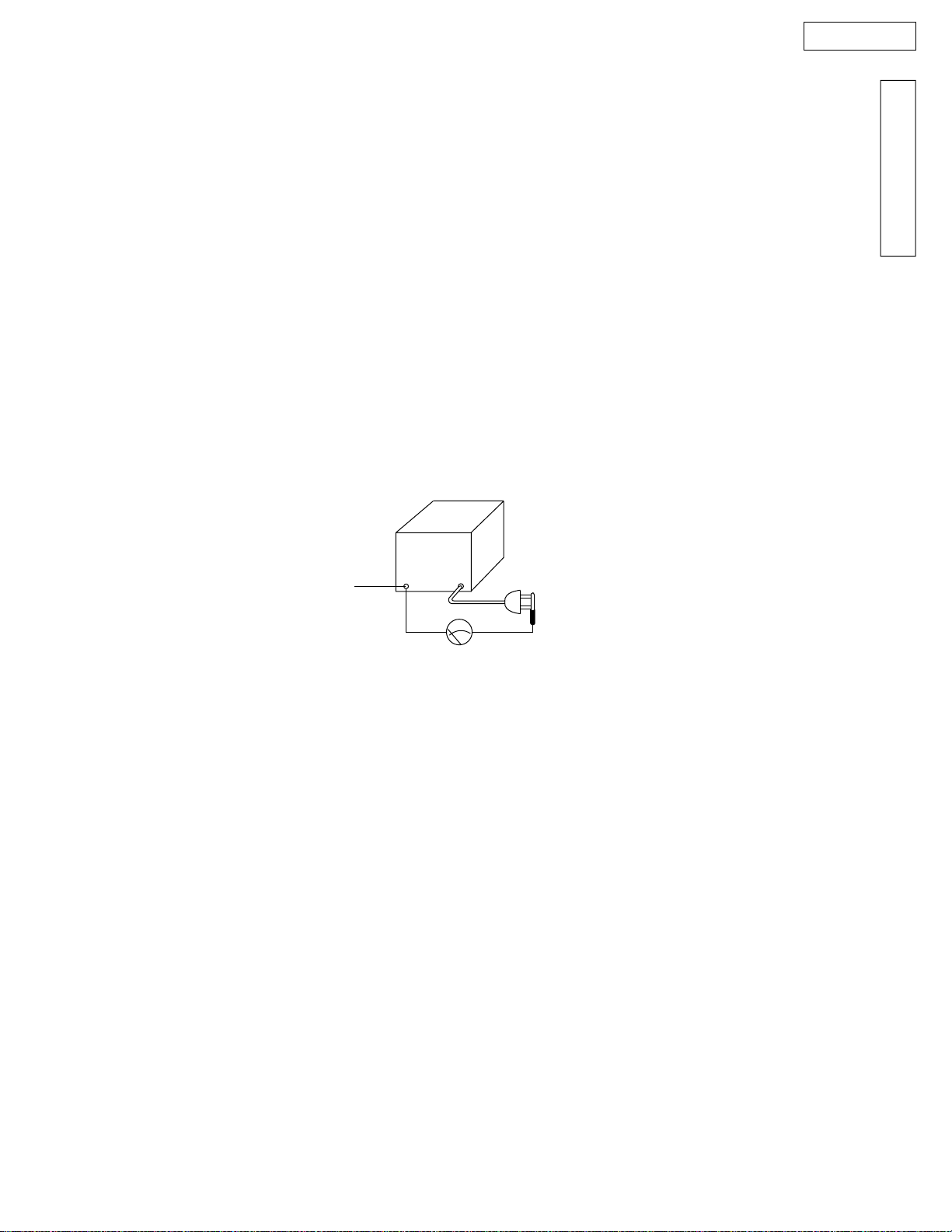
INSULATION RESISTANCE TEST
1. Unplug the power cord and short the two prongs of the plug with a jumper wire.
2. Turn on the power switch.
3. Measure the resistance value with an ohmmeter between the jumpered AC plug and each exposed metal cabinet part.
(screwheads, control shafts, handle brackets, etc.)
Note: Some exposed parts may be isolated from the chassis by design. These will read infinity.
4. If the measurement is outside the specified limits, there is a possibility of a shock hazard.
The equipment should be repaired and rechecked before it is returned to the customer.
INTRODUCTION
Exposed
metal
part
Ohmmeter
Resistance = more than 5M 
(at DC 500 V)
FOR SERVICE TECHNICIANS
ICs and LSIs are vulnerable to static electricity.
When repairing, the following precautions will help prevent recurring malfunctions.
1) Cover the plastic parts boxes with aluminum foil.
2) Ground the soldering irons.
3) Use a conductive mat on the worktable.
4) Do not touch the IC or LSI pins with bare fingers.
|5 |
KX-FT57E
BATTERY CAUTION
SAFETY CAUTIONS FOR LITHIUM BATTERY
(FOR UNITED KINGDOM)
THE LITHIUM BATTERY IS A CRITICAL COMPONENT
TYPE NUMBER CR2032 (BATT) MANUFACTURED BY MATSUSHITA
CR2032 (BATT) SONY
IT MUST NEVER BE SUBJECTED TO EXCESSIVE HEAT OR DISCHARGE. IT MUST THEREFORE ONLY BE FITTED
IN EQUIPMENT DESIGNED SPECIFICALLY FOR ITS USE.
REPLACEMENT BATTERIES MUST BE OF AN APPROVED TYPE AND MANUFACTURER AS INDICATED ABOVE.
THEY MUST BE FITTED IN THE SAME MANNER AND LOCATION AS THE ORIGINAL BATTERY, WITH THE CORRECT
POLARITY CONNECTIONS OBSERVED.
DO NOT ATTEMPT TO RE-CHARGE THE OLD BATTERY OR RE-USE IT FOR ANY OTHER PURPOSE. IT SHOULD BE
DISPOSED OF IN WASTE PRODUCTS DESTINED FOR BURIAL RATHER THAN INCINERATION.
WARNING
THE LITHIUM BATTERY IN THIS EQUIPMENT MUST ONLY BE REPLACED BY QUALIFIED PERSONNEL. WHEN
NECESSARY, CONTACT YOUR LOCAL PANASONIC SUPPLIER.
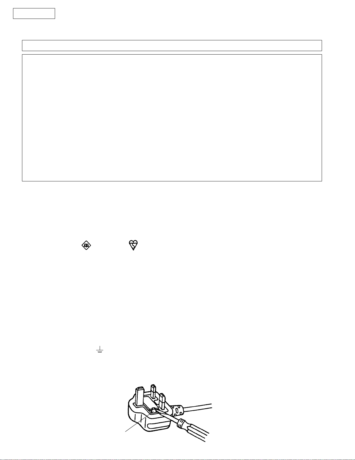
FITTING A PLUG TO THE MAINS LEAD
This appliance is supplied with a moulded three pin mains plug for your safety and convenience.
A5 amp fuse is fitted in this plug. Should the fuse need to be replaced please ensure that the replacement fuse has rating of
5 amps and that it is approved by ASTA or BSI to BS1362.
Check for the ASTA mark or the BSI mark on the body of the fuse.
If the plug contains a removable fuse cover you must ensure that it is refitted when the fuse is replaced. If you lose the fuse cover
the plug must not be used until a replacement cover is obtained. A replacement fuse cover can be purchased from your local
Panasonic Dealer.
IF THE FITTED MOULDED PLUG IS UNSUITABLE FOR THE SOCKET OUTLET IN YOUR HOME THEN THE FUSE SHOULD
BE REMOVED AND THE PLUG CUT OFF AND DISPOSED OF SAFELY.
THERE IS A DANGER OF SEVERE ELECTRICAL SHOCK IF THE CUT OFF PLUG IS INSERTED INTO ANY 13 AMP SOCKET.
If a new plug is to be fitted please observe the wiring code as shown below.
WARNING : THIS APPLIANCE MUST BE EARTHED.
IMPORTANT : The wires in this mains leads are colored in accordance with the following code:
Green-and-yellow: Earth
Blue: Neutral
Brown: Live
As the colors of the wires in the mains lead of this appliance may not correspond with the colored markings identifying the
terminals in your plug, proceed as follows.
The wire which is colored GREEN-AND-YELLOW must be connected to the terminal in the plug which is marked with the letter
E or by the safety earth symbol or colored GREEN or GREEN-AND-YELLOW.
The wire which is colored BLUE must be connected to the terminal in the plug which is marked with the letter N or colored
BLACK. The wire which is colored BROWN must be connected to the terminal in the plug which is marked with the letter L or
colored RED.
How to replace the fuse : Open the-fuse compartment with a screwdriver and replace the fuse and fuse cover.
FUSE
|6 |
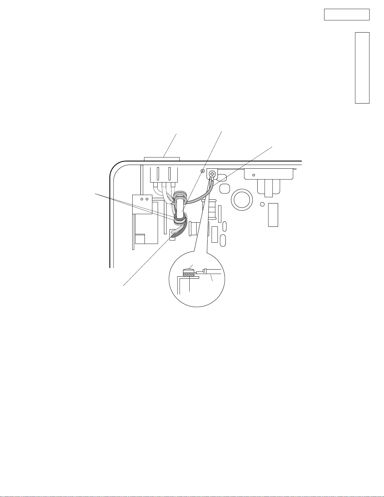
AC CAUTION
For your safety, before closing the lower cabinet , please check the following precautions.
The earth lead is fixed by the screw.
The AC connector is connected properly.
Wrap the AC leads around the core 2 times.
Wrap the Earth lead around the core 3 times.
(BOTTOM VIEW)
Earth Lead
AC lnlet
AC Lead
(Ferrite Core)
Earth Lead
KX-FT57E
INTRODUCTION
AC Connector
Screw
Washer
Earth
Lead
|7 |
KX-FT57E
PERSONAL SAFETY PRECAUTIONS
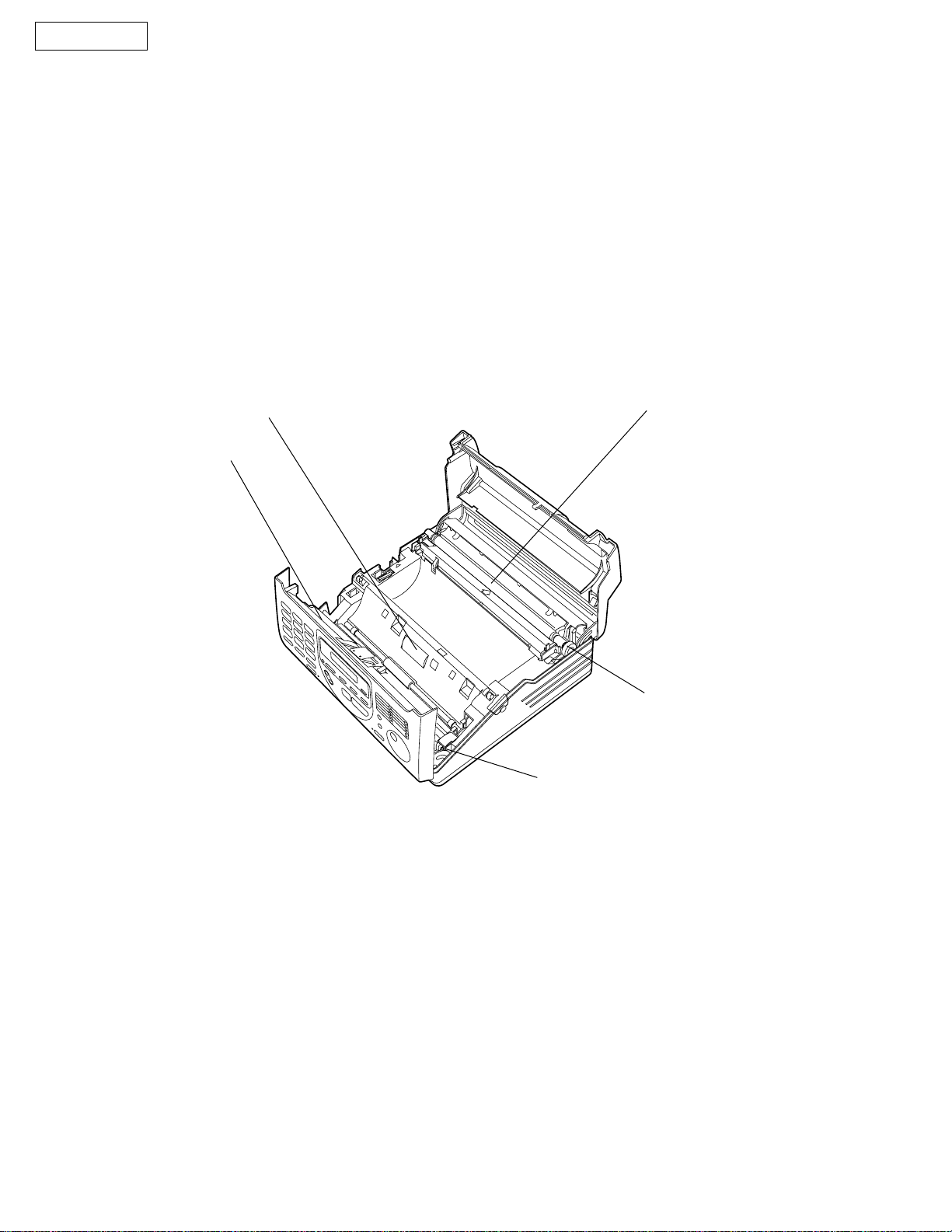
Be careful not to let your hair, clothes, fingers, accessories, etc., become caught in any of the moving sections of the unit. These
are driven by the carriage gear, paper feed roller, pressure roller, eject roller, spur, pick-up roller, etc., which are driven by the
paper feed motor. The separation roller and document feed roller are rotated by the document feed motor via a gear. Also, the
spurs are metal and sharply pointed. Be careful not to touch them with your hands.
Separation roller
Document rollers
Recording paper roller
Recording paper gear
Document feed gear
|8 |

Applicable Lines:
KX-FT57E
SPECIFICATIONS
INTRODUCTION
Public Switched Telephone Network
Document Size:
Effective Scanning Width:
Printing Paper Size:
Effective Printing Width:
Transmission Time*:
Scanning Density:
Halftone Level:
Scanner Type:
Printer Type:
Data Compression System:
Modem Speed:
Operating Environment:
Dimensions (H ~W ~D):
Mass (Weight):
Max. 216 mm in width
Max. 600 mm in length
208 mm
216 mm ~ max. 50 m roll
208 mm
Approx.15 s/page (Original mode)
Approx.30 s/page (G3 Normal mode)
Horizontal : 8 pels/mm
Vertical : 3.85 lines/mm–Standard mode
7.7 lines/mm–Fine/Half tone mode
15.4 lines/mm–Super fine mode
64-level
CCD image sensor
Thermal printing
Modified Huffman (MH), Modified READ (MR)
9,600/7,200/4,800/2,400 bps; Automatic Fallback
5–35 , 45–85 % RH (Relative Humidity)
118 ~351 ~265 mm
Approx. 3.7 kg
Power Consumption:
Power Supply:
Memory Capacity:
* Transmission speed depends upon the contents of the pages,
resolution, telephone line conditions and capability of the other
party's machine.
The 15 second speed is based upon the CCITT No. 1 Test
Chart on the condition that memory transmission is performed.
** If both fax documents nad voice messages are recorded in
memory, the corresponding capacities above will be shortened.
*** Recording time may be reduced by the calling party's
background noise.
Standby: Approx. 6.5 W
Transmission: Approx. 16 W
Reception: Approx. 23 W (When receiving the CCITT No. 1 Test Chart)
Copy: Approx. 32 W (When copying the CCITT No. 1 Test Chart)
Maximum: Approx. 120 W
220–240 V AC, 50 Hz
Voice memory: Approx. 18 minutes of recording time including the greeting
message***
Fax memory: Approx. 13 pages of memory reception
(Based on the CCITT No. 1 Test Chart in standard resolution)
Note:
• Any details given in these instructions are subject to change without notice.
• The pictures and illustrations in these instructions may vary slightly from the actual product.
|9 |
KX-FT57E
CCITT NO.1 TEST CHART (Actual size)
|10 |
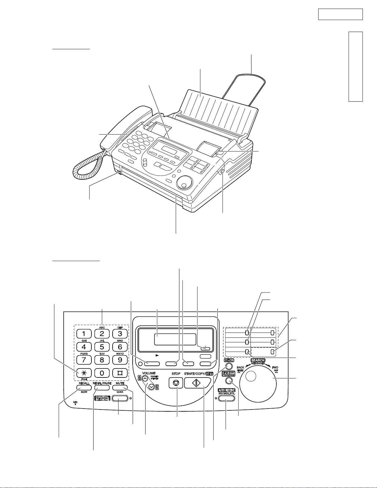
Front View
Speaker
KX-FT57E
LOCATION OF CONTROLS
INTRODUCTION
Paper stacker
Document feeder tray
Document entrance
Document guides
Microphone
Control panel
l
Used to change from pulse
to tone during dialing.
l
Used as a hook switch.
l
Used for slow play back.
l
Used to redial the last number dialed.
l
Used to insert a pause during dialing.
l
Used to play recorded
messages.
Dial keypad
l
Used for speaker
operation.
l
Used for voice muting.
l
Used for quick playback.
l
Used to adjust volumes.
l
Used to select feature
settings during programming.
Document exit
Display panel
PLAY
MESSAGES
Front lid open button
l
Used to record greeting messages.
l
Used to record memo messages and
a telephone conversation.
l
Used to erase recorded messages.
l
Used to erase your own recorded greeting messages.
l
Used to select a resolution.
l
Used to print a quick
reference.
l
Used to confirm a stored
telephone number.
RESOLUTION
CALLS
HELPERASERECORD
l
Used to stop an
operation or cancel
programming.
l
Used to initiate or exit programming.
l
Used to initiate fax transmission, reception or copying.
l
Used to store a setting during programming.
l
Used to insert a hyphen.
l
Used to insert one character or one
space.
1
HYPHEN
6
2
7
INSERT
3
8
SECRET
l
Used to store or edit names and
4
9
5
10
NAME/ TEL NO.
LOWER
telephone numbers.
l
Used to turn on/off the auto answer mode.
l
Used for the One-Touch Dial.
l
Used as command keys.
l
Used to confirm a stored
telephone number.
l
Used to select stations 6-10
for the One-Touch Dial.
l
Used to keep the telephone
number secret.
l
Used to search for a stored
name.
l
Used to select characters
during programming.
l
Used to select the basic features
during programming.
l
Used to skip and/or repeat the
recorded messages in the
answering device.
|11 |

KX-FT57E
FEATURES
General
Desktop type
LCD (Liquid Crystal Display) readout
Automatic paper cutter
Silent ring fax recognition system
Help function
Copier function
Facsimile
Automatic document feeder (up to 15 sheets)
64-level halftones
Resolution: standard/fine/super fine/halftone
Delayed transmission
Overseas transmission mode
Remote fax receiving using an extension phone
Junk mail prohibitor
Digital answering system
Voice mailbox
Tone remote control system
Integrated telephone system
One-touch dialer (10 phone number)
50-station speed dialer
Electronic telephone directory
Digital Hands-free speaker phone
|12 |
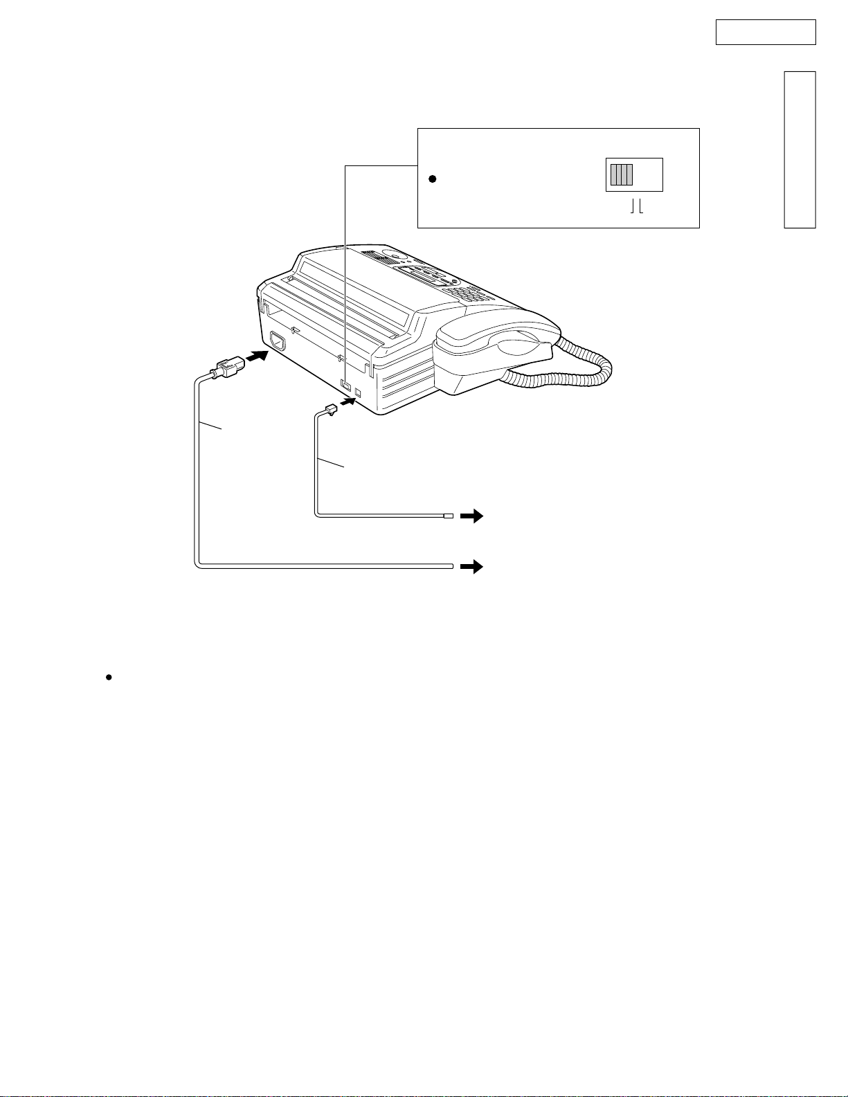
CONNECTION
KX-FT57E
INTRODUCTION
Power cord
Dialing mode switch:
Set to TONE.
If you cannot dial,
set to PULSE.
Telephone line cord
DIALING MODE
PULSETONE
To a single telephone line socket
To the power outlet
(220-240V)
Note:
This machine should be connected to a nearby power outlet that is easily accessible.
|13 |
KX-FT57E
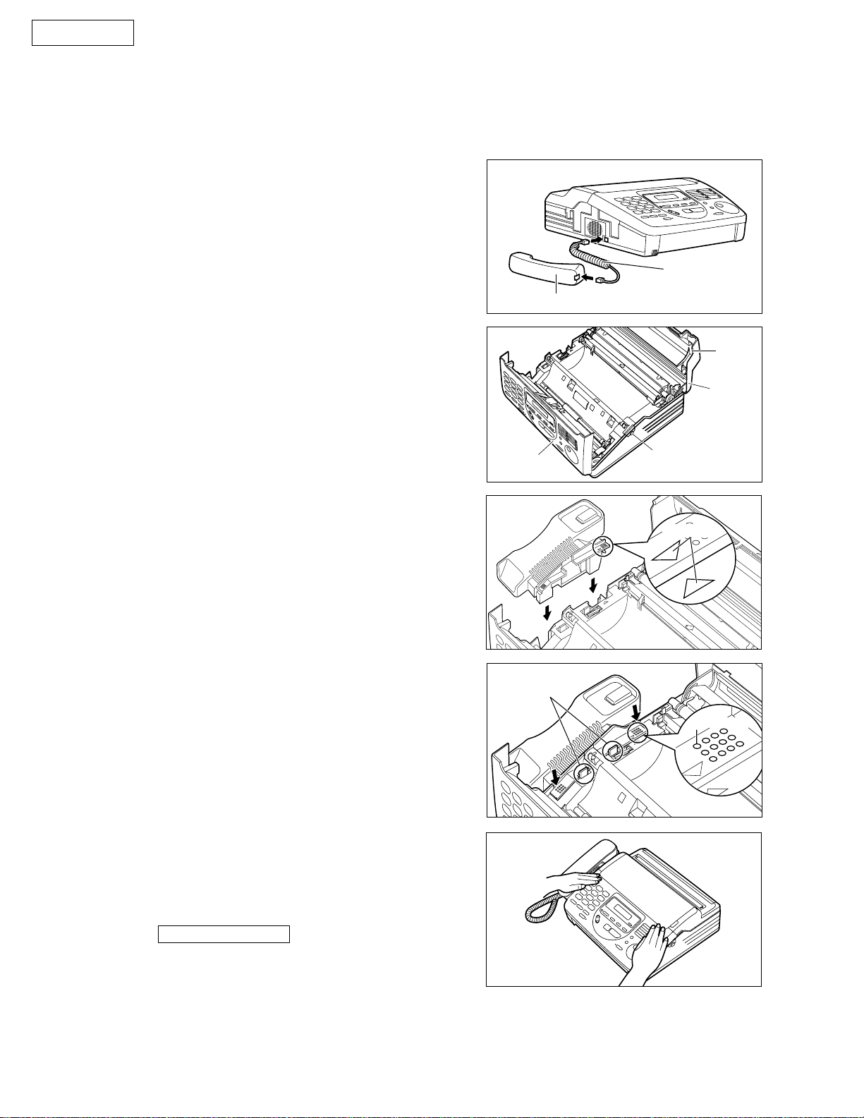
1. Installing the handset cradle
Connect the handset cord.
1
Open the front lid by pressing the front lid open
2
3
button.
Open the back lid by lifting up the tabs located
on the both side.
INSTALLATION
Handset
Front lid
Handset cord
Tab
Black lid
Front lid open
button
4
5
6
Insert the handset cradle by matching the triangles.
Press down on the dotted mark on the handset
cradle until it clicks into place.
Make sure the two hooks lock the handset
•
cradle firmly.
Place the handset on the handset cradle and close
the lids securely.
If the handset cradle is not installed correctly, the
•
unit will show the following message when the
power is switched on.
CHECK CRADLE
Check steps 4 and 5 again.
Triangles
Hooks
Dotted mark
Note:
To save space or when using the unit mainly for faxes, you can use the DIGITAL SP-PHONE button on the
•
unit without the handset and cradle.
|14 |

2. Installing the recording paper
KX-FT57E
1
2
3
Open the back lid by lifting up the tabs located
on the both sides.
Install a recording paper roll.
Make sure that the shiny side of the paper is
•
facing down.
incorrectcorrect
If the paper is secured with glue or tape, cut
•
approx. 150 mm from the beginning of the roll.
Insert the leading edge of the recording paper
between the recording paper roller and the silver
plate, then pull it a few centimeters out of the unit.
Make sure that there is no slack in the paper roll.
•
INTRODUCTION
Tab
Recording paper roller
Silver plate
Close the back lid by gently pressing down on both
4
Note:
•
excessive thermal head wear may occur.
ends.
Only use the included roll of paper or specified recording paper, or the print quality may be affected and/or
3. Installing the paper stacker
Install the paper stacker.
Paper stacker
|15 |
KX-FT57E
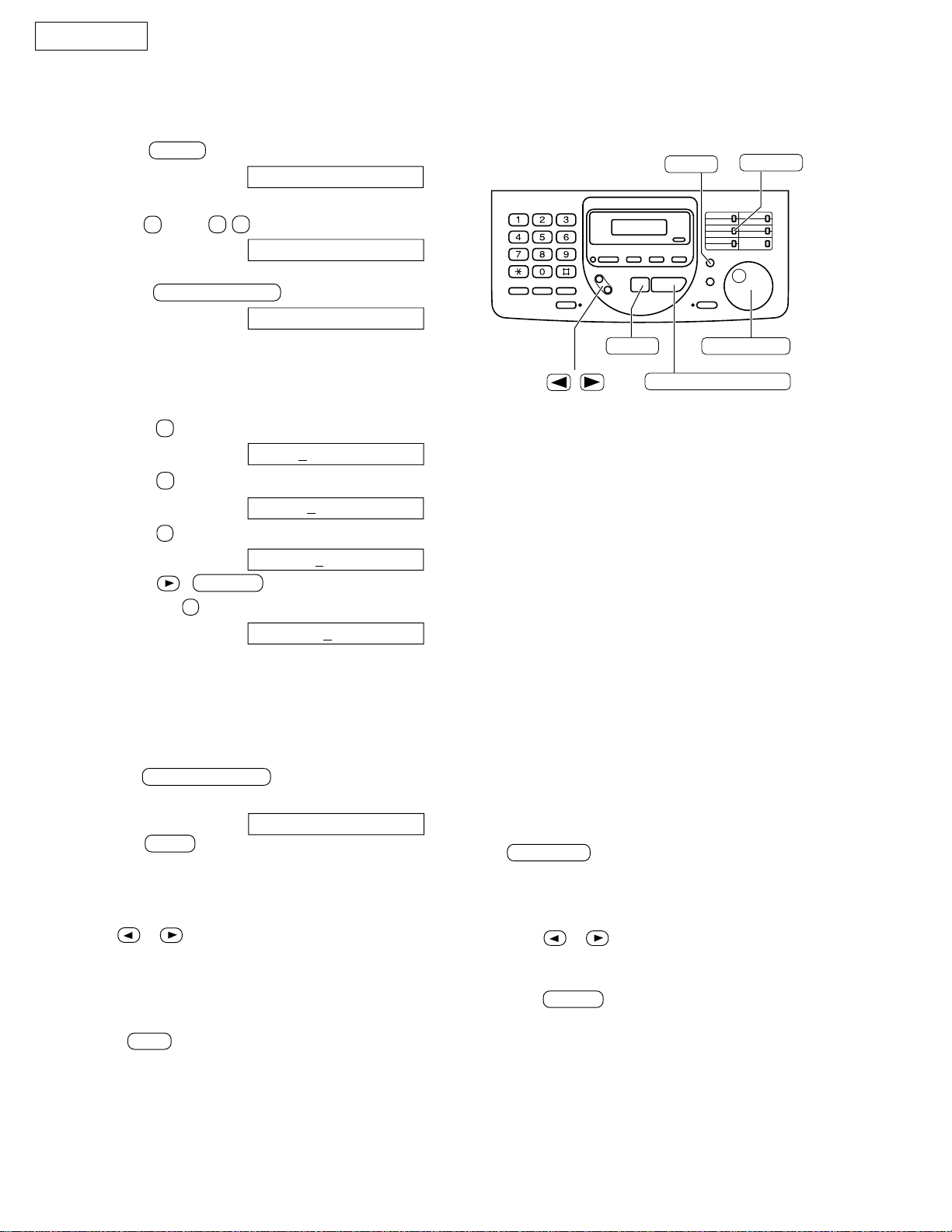
4. SETTING YOUR LOGO
The logo can be a company, division or name.
(1) Press MENU .
Display: 1. SYSTEM SET UP
(2) Press # , then 0 2 .
YOUR LOGO
(3) Press START/COPY/SET .
LOGO=
(4) Enter your logo, up to 30 characters, by following the
instructions on the next page.
Example (using the dial keypad): Bill
1. Press 2 twice.
LOGO=
B
2. Press 4 six times.
LOGO=B
3. Press 5 six times.
LOGO=Bi
4. Press ( VOLUME ) to remove the cursor
and press 5 six times.
LOGO=Bil
i
l
l
/
MENU
STOP
(Delete)
START/COPY/SET
INSERT
EASY DIAL
• To enter the same number key continuously,
move the cursor to the next space.
(5) Press START/COPY/SET .
SYSTEM SET UP [ ]
(6) Press MENU .
To correct a mistake
• Use or to move the cursor to the incorrect
character, then make the corrections.
To delete a character
• Move the cursor to the character you want to delete and
press STOP .
Note:
• You can enter your logo by rotating
EASY DIAL (See next page).
To insert a character
1. Press or to move the cursor to the
position to the right of where you want to
insert the character.
2. Press INSERT to insert a space and enter
the character.
|16 |
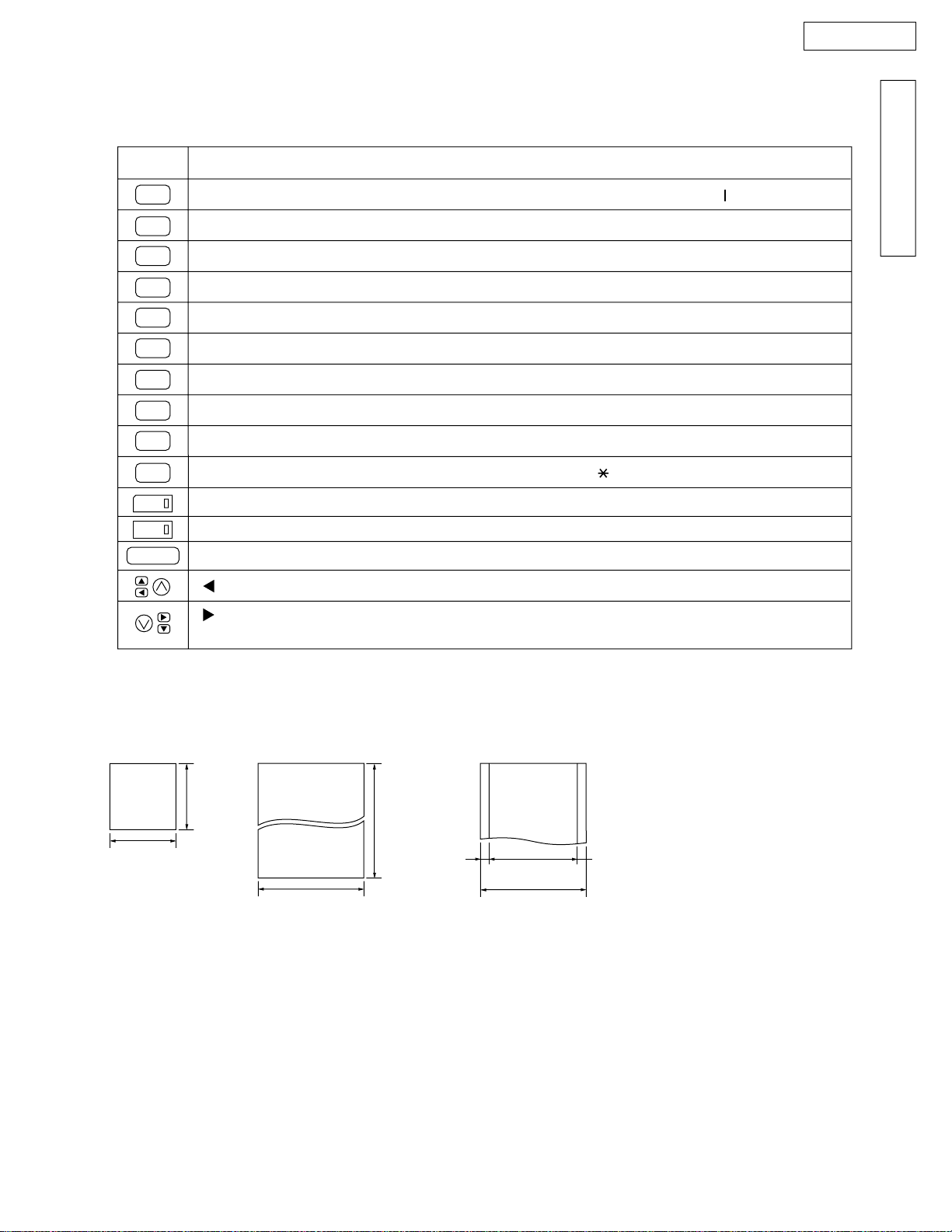
Selecting characters with the dial keypad
Pressing the dial keys will select a character as shown below.
KX-FT57E
INTRODUCTION
Keys
1
2
3
4
5
6
7
8
9
0
1
2
STOP
Characters
1
[
]
{
}
+
–/=, .
A
B
C
a
b
D
E
F
d
e
G
H
I
g
h
J
K
L
j
k
M
P
T
W
O
N
Q
U
X
m
n
R
S
p
V
t
u
Y
Z
w
0()<>!"#$%
2
c
3
f
4
i
5
l
6
o
rs7
q
8
v
yz9
x
&
HYPHEN key (To insert a hyphen.)
INSERT key (To insert a one character or one space.)
Delete key (To delete a character.)
key (To move the cursor to the left.)
,
–
\
:
@
;
?
^
f
¤
key (To move the cursor to the right.)
To enter the another character using the same number key, move the cursor to the next space.
Documents you can send
Minimum size Maximum size Effective scanning area Document weight
Scanned
128 mm
128 mm
216 mm
Note:
Remove clips, staples or other similar fastening objects.
Check that ink, paste or correction fluid has dried.
Do not send the following types of documents. Use copies for fax transmission.
– Chemically treated paper such as carbon or carbonless duplicating paper
– Electrostatically charged paper
– Heavily curled, creased or torn paper
– Paper with a coated surface
– Paper with a faint image
– Paper with printing on the opposite side that can be seen through the front (e.g. newspaper)
600 mm
4 mm
area
208 mm
Paper width
216 mm
Single sheet:
45 to 90 g/m
Multiple sheets:
60 to 80 g/m
2
2
|17 |
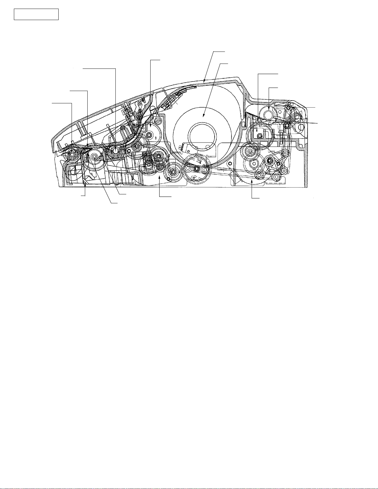
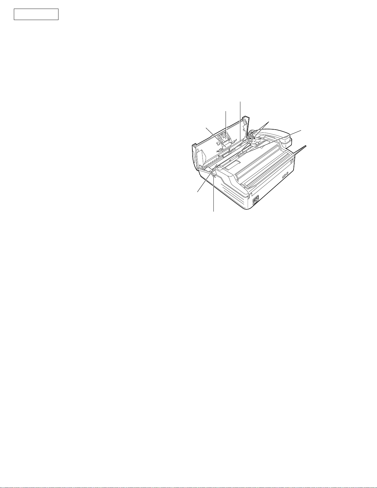
KX-FT57E
Document
Feed Roller
COMPONENT LOCATIONS
Recording Paper Cover
Separation Roller
Recording Paper
Thermal Head
Target Glass
Document
Feed Roller
Mirror
Lens
LED Array
Transmission Motor
MAINTENANCE ITEMS
1. OUTLINE
MAINTENANCE AND REPAIRS ARE PERFORMED USING THE FOLLOWING STEPS.
Recording Paper Roller
Cutter
Reception Motor
1) Periodic maintenance
Inspect the equipment periodically and if necessary, clean as required.
2) Check for breakdowns
Look for signs of trouble and consider how the problems arose.
If the equipment can still be used, perform copying, self -testing or communications testing.
3) Check equipment
Perform copying, self testing and communications testing to determine if the problem originates from the transmitter,
receiver or telephone line.
4) Determine causes
Determine the causes of the equipment problem by troubleshooting.
5) Equipment repairs
Repair or replace the defective parts and take appropriate measures at this stage to ensure that the problem does
not recur.
6) Confirm normal operation of the equipment
After completing the repairs, conduct copying, self testing and communications testing to confirm that the equipment
operates normally.
7) Record keeping
Make a record of the measures taken to rectify the problem for future reference.
|18 |
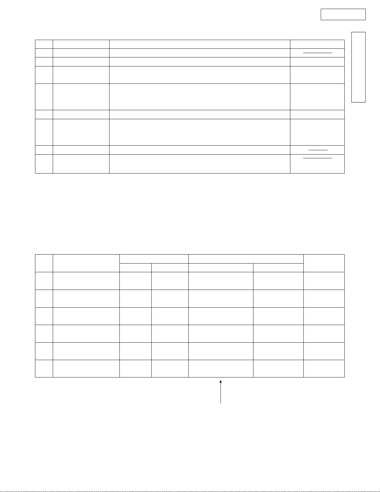
2-1. MAINTENANCE LIST
KX-FT57E
NO.
1
2
3
4
5
6
7
8
OPERATION
Document Path
Rollers
Recording Paper
Roller
Thermal Head
LED Array
Sensors
Mirrors and Lens
Abnormal, wear and
tear or loose parts
CHECK ITEM
Remove any foreign matter such as a scrap of paper.
If a roller is dirty, clean it with a damp cloth, then let it dry thoroughly.
If the platen is dirty, clean it with a damp cloth, then let it dry thoroughly.
Remove the paper before cleaning.
If the thermal head is dirty, clean the printing surface with a cloth
moistened with denatured alcohol (alcohol without water), then let it dry
thoroughly.
If the LED array is dirty, clean the glass with a dry soft cloth.
Confirm the operation of the following sensors: recording paper sensor
(SW2), document sensor (PI302), read position sensor (PI301), cover
open sensor (SW5), and JAM sensor (SW3).
If the mirror and lens are dirty, clean them with a dry soft cloth.
Replace the part. Be sure that all of the part's screws are tightened.
REMARKS
See page 20.
See page 114.
See page 116.
See page 20.
See pages 84, 85.
INTRODUCTION
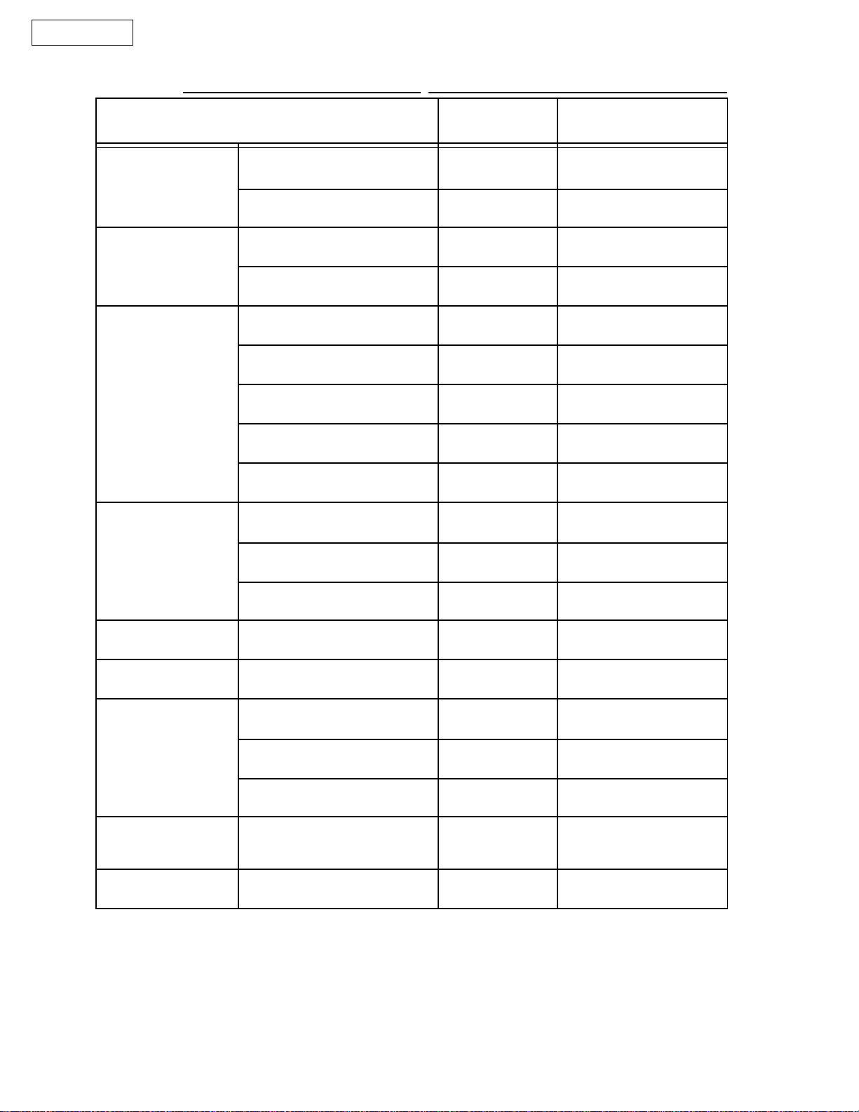
2-2. MAINTENANCE CYCLE
No.
Separation Roller
1
(Ref. No. 58)
Separation Rubber
2
(Ref. No. 23)
Feed Roller
3
(Ref. No. 49, 53)
Target Glass
4
(Ref. No. 171)
Thermal Head
5
(Ref. No. 59)
Recording Paper Roller
6
(Ref. No. 112)
Items
3 months
3 months
3 months
3 months
3 months
3 months
Cycle
Cleaning
Procedure
See page. 20.
––––
See page. 20.
See page. 20.
See page. 116.
See page. 114
Replacement
Cycle
7 years
(63,000 documents)
7 years
(63,000 documents)
7 years
(63,000 documents)
7 years
(63,000 documents)
7 years
(63,000 documents)
7 years
.
(63,000 documents)
These values are only an indication and may vary depending on
actual usage conditions.
Procedure
See page 113.
––––
See page 113.
––––
See page 116.
See page 114.
Remarks
|19 |
KX-FT57E
CLEANING THE INSIDE OF THE UNIT
If misfeeding occurs frequently, or dirty patterns or black bands appear on a copied or transmitted document,
clean the document feeder rollers, separation roller, sub roller, rubber flap, white plate and glass.
Disconnect the power cord and the telephone line
1
2
3
4
5
6
cord.
Open the front lid by pressing the front lid open
button.
Clean the document feeder rollers and roller with a
cloth moistened with isopropyl rubbing alcohol, and
let dry thoroughly.
Clean the white plate and glass with a soft dry
cloth.
Clean the front lid by gently pressing down on both
ends.
Connect the power cord and the telephone line
cord.
Rubber flap
Sub roller
Glass
White plate
Document
feeder rollers
Separation roller
Caution:
Do not use paper products (such as paper towels or
•
tissues) to clean the inside of the unit.
Front lid open button
|20 |

TROUBLESHOOTING GUIDE
Page
1. Troubleshooting Summary .................................................................... 22
1-1. Troubleshooting..................................................................... 22
1-2. Precautions............................................................................ 22
2. User Recoverable Errors....................................................................... 23
3. Troubleshooting Details................................................................... 24~91
KX-FT57E
TROUBLESHOOTING GUIDE
3-1. Outline ................................................................................... 24
3-2. Starting troubleshooting......................................................... 24
3-3. Troubleshooting items table .................................................. 25
3-4. Simple check-list.................................................................... 26
3-5. ADF section ..................................................................... 27~36
3-6. Communication section ................................................... 37~57
3-7. Digital board section ........................................................ 58~72
3-8. Analog board section....................................................... 73~76
3-9. Digital Speaker phone section......................................... 77, 78
3-10.Power supply section....................................................... 79~82
3-11.Operation board section ........................................................ 83
3-12.Sensor section ................................................................. 84, 85
3-13.Read section.................................................................... 86~90
3-14.Thermal head section ............................................................ 91
4. Programming and Lists ................................................................... 92~97
5. Test Functions................................................................................. 98, 99
|21 |

KX-FT57E
1. TROUBLESHOOTING SUMMARY
1-1. Troubleshooting
After having confirmed the abnormal condition by asking the user, troubleshoot according to the instructions in
Observe the following precautions when troubleshooting.
1-2. Precautions
1) If there is trouble with the print quality or the paper feed, first check that the installation space and print
paper meets the specifications. Then check that the paper selection lever/paper thickness lever is set
correctly and the paper is set correctly without any slack.
2) Before troubleshooting, first check that the connectors and cables are connected correctly and securely.
Moreover, if the abnormality occurs randomly, check very carefully.
3) When testing with the AC power connected to the unit, exercise utmost care when handling the electric parts
in order to avoid electric shock and short-circuits.
4) After troubleshooting, double check that you have not forgotten any connectors, left any loose screws, etc.
5) Always test to verify that the unit is working normally.
|22 |
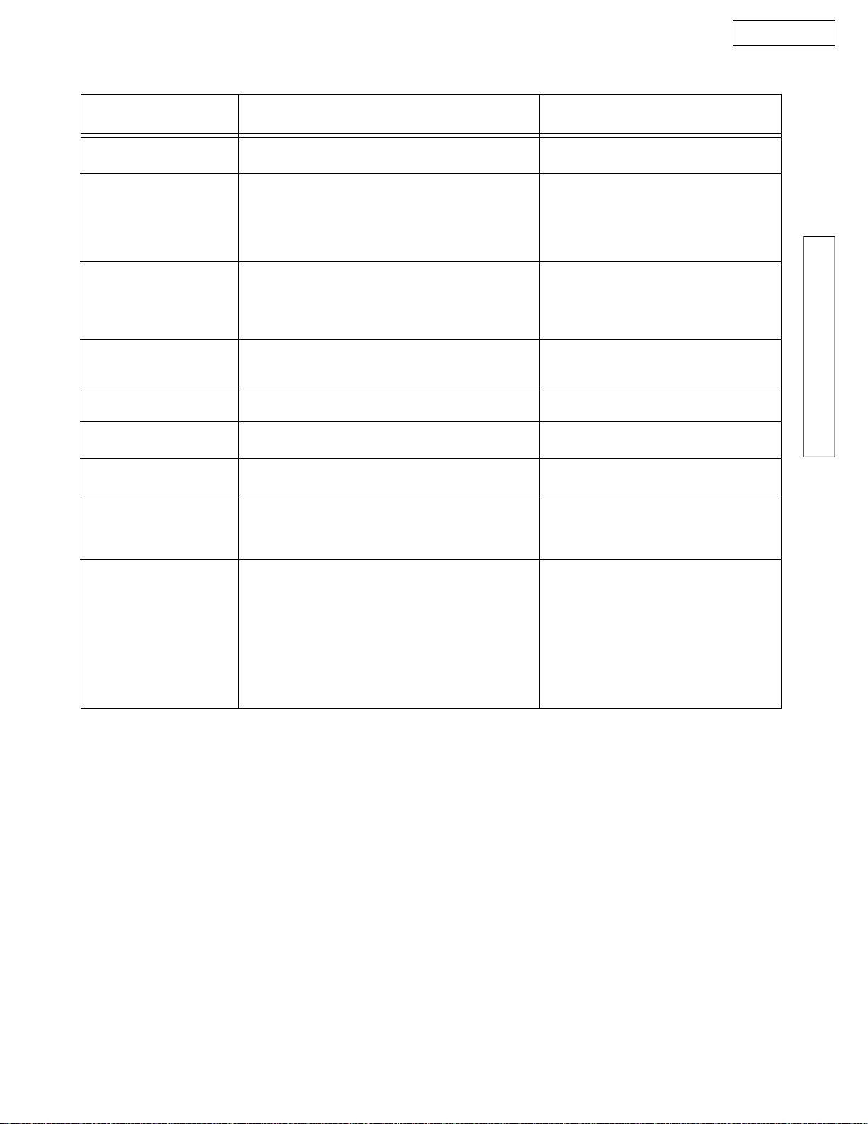
2. USER RECOVERABLE ERRORS
If the unit detects a problems, the following messages will appear on the display.
DISPLAY MESSAGE CAUSE AND REMEDY
There is something wrong with the unit. Contact your service personnel.
CALL SERVICE
CHECK COVER
CHECK CRADLE
CHECK DOCUMENT
•
[Check the thermistor on the thermal head and connector lead. (for technicians)]
[This error is displayed when the thermal head does not warm up.]
The back lid is open. Close it.
•
The handset and handset cradle have been removed when you connect the power
•
cord.
--- When you want to use the handset and handset cradle, install the handset cradle
correctly.
--- When you do not use the handset and handset cradle, set the handset switch to
NO HANDSET. Then, disconnect and connect the power cord again.
The document is not fed into the unit properly. Reinsert the document.
•
If the misfeeding occurs frequently, clean the document feeder rollers inside the unit.
If the problem remains, adjust the feeder pressure.
Attempted to transmit a document longer than 600 mm (23
•
and remove the document. Divide the document into two or more sheets and try again.
[If you do wish to devide the document, change the service code #559 to "OFF". Refer
to page 94.]
5
/8"). Pres the STOP button
KX-FT57E
TROUBLESHOOTING GUIDE
CHECK MEMORY
DIRECTORY FULL
FAX IN MEMORY
MEMORY FULL
NO RESPONSE
NO TEL GREETING
OUT OF PAPER
PAPER JAMMED
POLLING ERROR
REDIAL TIME OUT
Memory (phone numbers, parameters, etc.) has been erased. Re-program.
•
There is no space to store new stations in the EASY DIAL directory. Edit or erase
•
unnecessary stations.
The unit has documents in memory. Install a new recording paper roll or clear the
•
jammed paper.
There is no room left in memory to record a message. Erase some or all of the
•
messages.
The memory is full of received documents. Install a new recording paper roll or clear
•
the jammed paper.
The receiving unit is busy or ran out of recording paper. Try again.
•
The TEL/FAX greeting message has not been recorded. Record a greeting message.
•
The unit ran out of recording paper. Install a new recording paper roll.
•
A recording paper jam occurred. Clear the jammed paper.
•
The other fax machine does not provide the polling function. Check with the other
•
party.
The receiving unit is busy or ran out of recording paper. Try again.
•
REMOVE DOCUMENT
TRANSMIT ERROR
UNIT OVERHEATED
The document is jammed. Remove the jammed document.
•
Attempted to transmit a document longer than 600 mm (23
•
and remove the document. Divide the document into two or more sheets and try again.
A transmission error occurred. Try again.
•
The unit is too hot. Let the unit cool down.
•
[If many copies are nearly all black, this message will be displayed.]
[When this occurs, open the front cover and let the unit cool down.]
|23 |
5
/8"). Press the STOP button
KX-FT57E
3. TROUBLESHOOTING OF DETAILS
3-1. OUTLINE
The troubleshooting guide provides a logical path of deduction to assist in locating a fault and suggests methods of restoring
the unit to full working condition. Use the reported symptoms of the fault to determine the best troubleshooting method.Even
difficult faults can be tracad to a specific block or area, for example, the "Digital Board"or "Image Sensor".
A variety of fault descriptions from customers often point to the same area and, for this reason, careful analysis of the
reported symptoms is required. After every repair, test all functions to ensure no problems are evident.
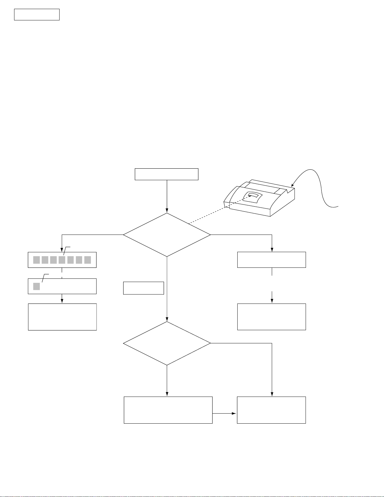
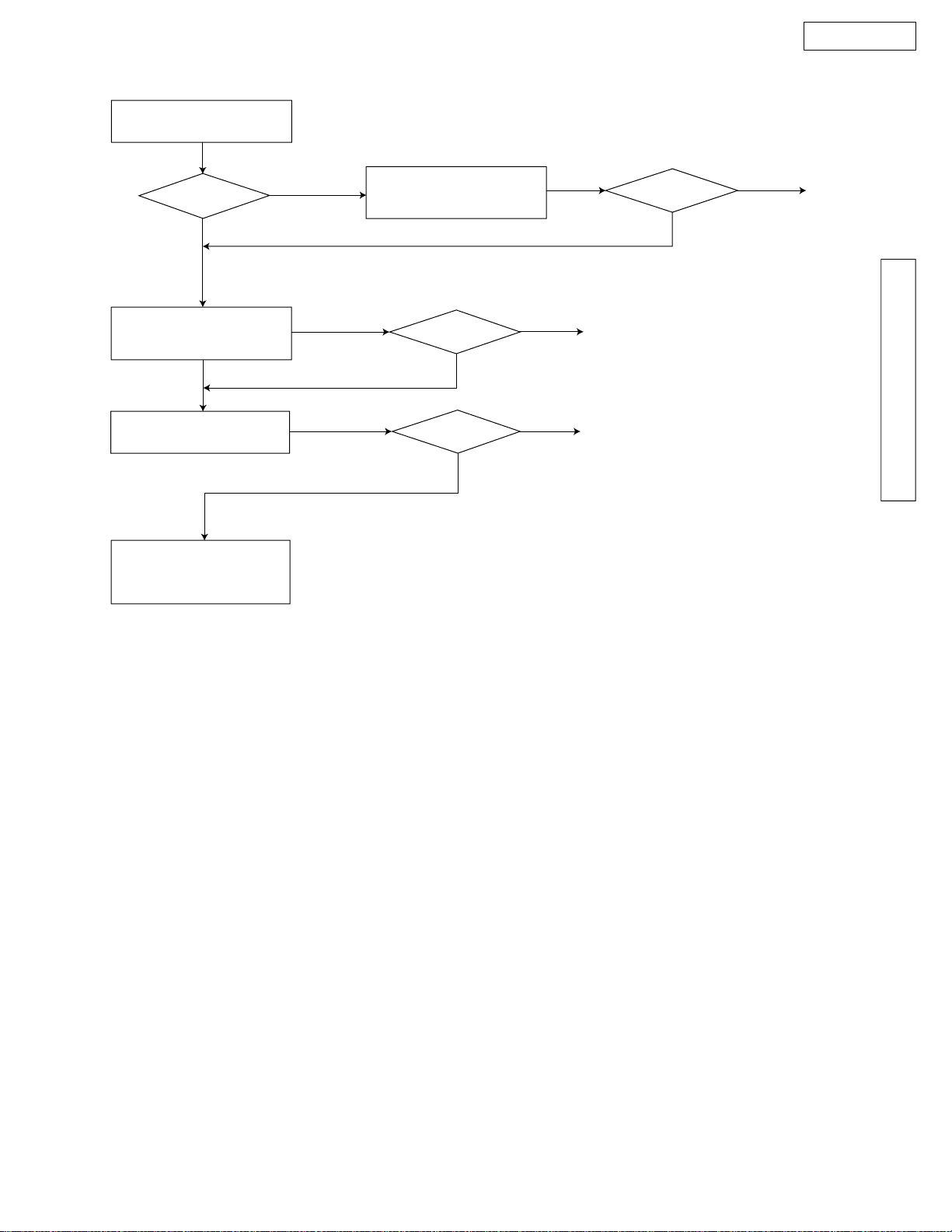
3-2. STARTING TROUBLESHOOTING
• Select the appropriate troubleshooting method according to the symptoms.
Power on.
Plug in the AC cord.
LCD
or
Blinking
See the digital board
section.
(See page 58.)
slightly changes
Check LCD.
LCD
12:00AM
good
Already known symptom
No
Yes
LCD
Blank LCD means that the power line
is broken (open-circuit).
See the digital board
section.
(See page 58.)
Blank
AC
Determine the symptom using
the check list. (See page 25.)
|24 |
See the table for
troubleshooting items.
3-3. TROUBLESHOOTING ITEMS TABLE
FUNCTION SYMPTOM PAGE
KX-FT57E
The unit doesn't work at all.
Printing
Paper paths section
Abnormal
mechanical sound
Cutter
Power supply
Operation panel
Sensor
No character or faint response in the LCD
Skewed sending image
Expanded printing
Image is distorted.
Black or White lateral lines on the printed copy.
No feed
Paper jam
Multiple feed
Skewed
Abnormal sound from the product
Can not cut the recording paper.
Voltage output is abnormal.
Keys are not accepted.
"PAPER JAMMED" is displayed.
"CHECK COVER" is displayed.
"CHECK DOCUMENT" is displayed.
Page 34
Page 34
Page 31
Page 32
Page 27
Page 28
Page 29
Page 30
Page 35
Page 33
Page 79
Page 83
Page 84
TROUBLESHOOTING GUIDE
Communication
FAX, TEL
(Analog board)
Can not communicate by fax.
An error code is displayed.
Can't talk.
DTMF tone doesn't work.
Handset/Monitor sound, volume
TAM doesn't work.
Digital speaker phone
Page 37
Page 37
Page 73
Page 73
Page 73
Page 73
Page 77
|25 |
KX-FT57E
3-4. SIMPLE CHECK LIST
SERIAL NO.
DATE
FAX operaton
Copy operation
Telephone operation
FUNCTION JUDGEMENT
Transmission
Receiving
FINE mode
HALF TONE mode
Handset transceiver/ receiver
Ringer sound
Dial operation
Volume operation
VOX detection
Key check
OK / NG
OK / NG
OK / NG
OK / NG
OK / NG
OK / NG
OK / NG
OK / NG
OK / NG
OK / NG
REFERENCE
Service code 815
ƒ
(Digital SP-Phone LED)
Service code 561
ƒ
Operation panel
Sensor
Digital speaker
phone
Digital TAM
LED check
LCD check
Sensor check
Greeting Rec/Play
Incoming message Rec/Play
Memo Rec/Play
OK / NG
OK / NG
OK / NG
OK / NG
OK / NG
OK / NG
OK / NG
Voice prompt OK / NG
Clock
OK / NG
ƒ
Check according to the service code referring
to the Test function on page 98.
Service code 557
Service code 558
Service code 815
ƒ
ƒ
ƒ
Service code 784
Check whether voice
prompt is played or not.
Check accuracy.
|26 |
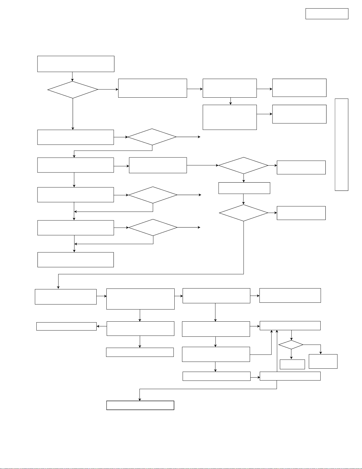
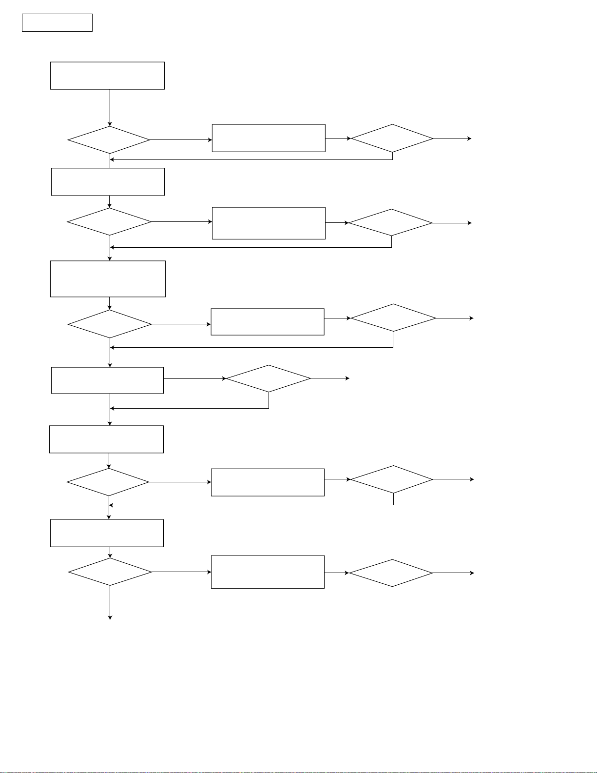
3-5. ADF (Auto document feed) SECTION
KX-FT57E
(1) No document feed
When setting a document,
confirm the beep tone.
OK?
YES
Clean the separation roller.
( page 114 )
Does the separation roller
rotate?
YES
Check the separation spring
and pad?
YES
NO
ƒ
When using thin paper etc., if the document will not feed,
refer to the feed pressure adjustment (page 101).
Check if separation
spring is distorted.
OK?
NG
Check the motor and
NO
connector.
NO
OK?
NG
OK
OK
NG
Check the sensor
lever movement.
Check the sensor
and digital board.
(pages 58 and 84)
END
END
OK
OK?
YES
Check the gear.
OK?
Replace the sensor
NG
lever.
NG
Replace the defective parts.
NG
Replace the motor
and connector.
NG
Replace the gear.
TROUBLESHOOTING GUIDE
Replace the separation
roller unit.
YES
Replace the operation cover
unit.
Go to the digital board
section. (page 58)
NO
Repair.
NO
Is the phase signal from
pins 73-77 of IC1 output?
Is the solder at pins 7377 of IC1 OK?
Replace IC7.
OK?
NG
YES
YES
OK
END
Is the voltage at emitter
of Q1 +24 V?
YES
Is the voltage at collector
of Q1 +24 V?
NO
Is the voltage at pin 11 of
IC7 less than 2V?
YES
Replace Q1.
YES
Check the power supply
unit section. (page 79)
Replace IC7.
OK?
YES
NO
NO
END
OK?
NO
Replace
the motor.
END
|27 |
KX-FT57E
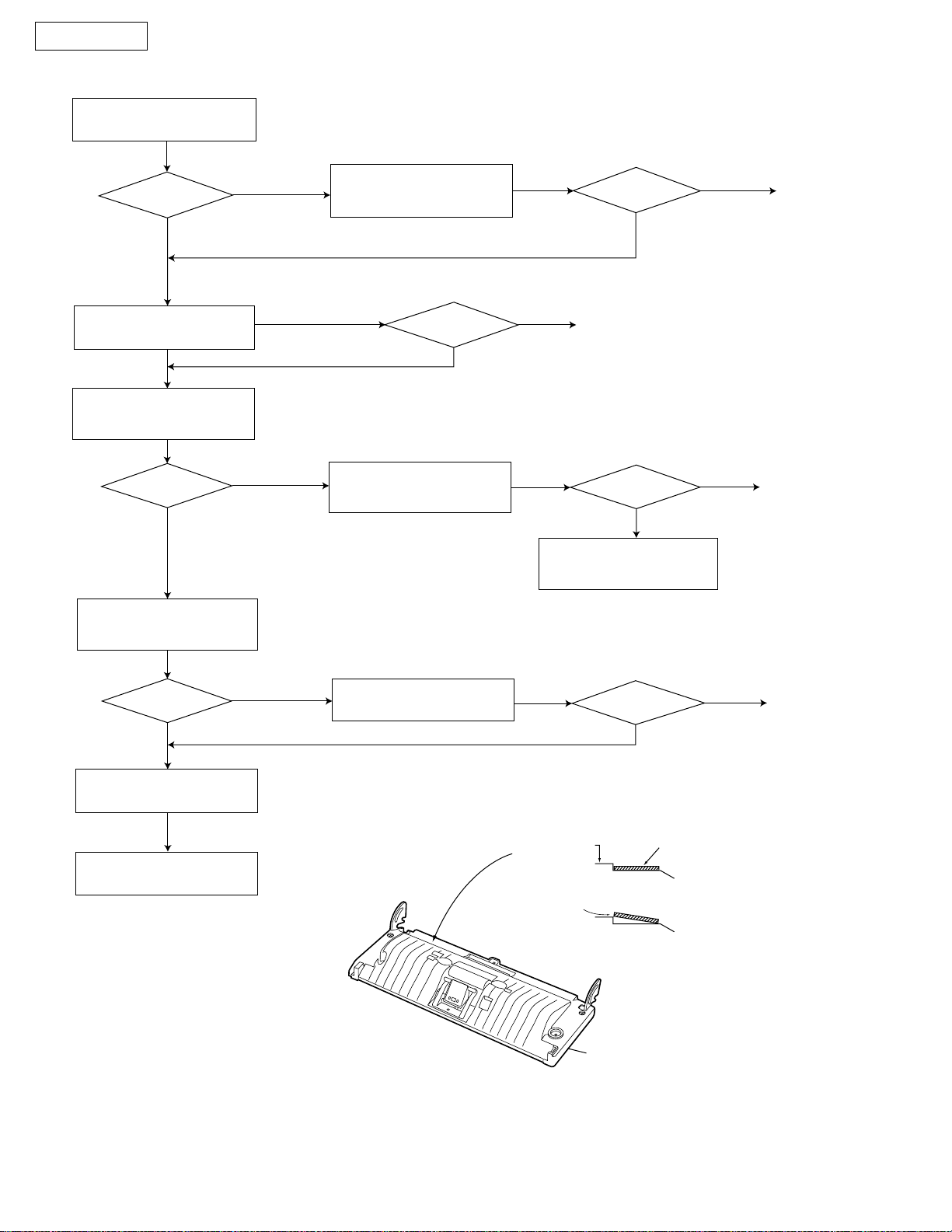
(2) Paper JAM
Check the feed route.
OK?
YES
Clean each of the rollers.
(pages 113 and 114 )
Check each of the
sensors movement.
OK?
YES
Check the paper jam for markings or objects stuck on the sheet.
NO
Confirm that the location tip of the read position
sensor lever works smoothly. [Use the sensor test function (page 98)]
NO
Clean or replace the
defective parts.
OK?
NG
Repair or replace the
sensor lever.
NG
OK
END
NG
Go to the sensor section.
(page 84)
OK?
OK?
OK
OK
Check if the sensor
reacts while the flag is
moving.
END
END
Check each roller
mount.
OK?
YES
Check the white plate.
NG
Replace the white plate.
Check that the separation, feed and pinch
rollers are attached correctly.
NO
Repair the defective parts.
Operation
cover
Document
OK?
NG
White Plate
Operation Board Cover
OK
OK
NG
END
|28 |
Fig. A
(3) Multiple feed
Check the separation pad.
ƒ
When using thin paper etc., if the document will not feed,
refer to the feed pressure adjustment (page 101).
Confirm whether the pad is dirty or not and
is attached correctly.
KX-FT57E
OK?
YES
Check if the separation
spring is distorted.
Clean each of the rollers.
(pages 113 and 114)
Replace the separation
pad, roller and pressure
spring.
NO
Clean or replace the
defective parts.
OK?
NG
OK?
NG
OK
OK
END
END
NG
OK?
OK
END
TROUBLESHOOTING GUIDE
|29 |
KX-FT57E
(4) Skew
Is the document setting
OK?
Check whether the document is folded and if
tape or staples are attached. Also check
if a different size document is set at
the same time.
OK?
YES
Check the feed route.
OK?
YES
Check the balance of
both separation pressure
springs.
OK?
YES
Clean each of the rollers.
(pages 113 and 114 )
NO
Check whether there are foreign
objects or missing parts.
NO
NO
Reset the document.
Clean or replace the
defective parts.
Replace the separation
pressure spring.
NG
OK?
OK
NG
NG
NG
END
OK?
OK?
OK?
OK
OK
OK
END
END
END
Check the white plate.
(Refer to Fig. A of page 28)
OK?
YES
Check the CCD unit.
OK?
END
NO
NO
Replace the white plate.
Repair or replace the
defective parts.
NG
OK?
OK?
OK
OK
END
END
|30 |
 Loading...