

Panasonic KX-FT21RS User Manual
PARSONAL FACSIMILE
KX-FT21RS
(Russia)
ORDER NO. KM79911336C3
© 1999 Kyushu Matsushita Electric Co., Ltd. All
rights reserved. Unauthorized copying and
distribution is a violation of law.

KX-FT21RS
CONTENTS
Page Page
1 INTRODUCTION 3
1.1. SAFETY PRECAUTIONS
1.2. INSULATION RESISTANCE TEST
1.3. FOR SERVICE TECHNICIANS
1.4. BATTERY CAUTION
1.5. AC CAUTION
1.6. PERSONAL SAFETY PRECAUTIONS
1.7. FEATURES
1.8. SPECIFICATIONS
1.9. OPTIONAL ACCESSORIES
1.10. CCITT No. 1 TEST CHART
1.11. LOCATION OF CONTROLS
1.12. CONNECTIONS
1.13. INSTALLATION
1.14. MAINTENANCE ITEMS AND COMPONENT LOCATIONS
2 TROUBLESHOOTING GUIDE
2.1. TROUBLESHOOTING SUMMARY
2.2. USER RECOVERABLE ERRORS
2.3. TROUBLESHOOTING DETAILS
2.4. PROGRAMMING AND LISTS
2.5. TEST FUNCTIONS
2.6. JOURNAL 3
3 ADJUSTMENTS
3.1. ADJUSTING THE FEED PRESSURE
4 DISASSEMBLY INSTRUCTIONS
5 HOW TO REPLACE THE FLAT PACKAGE IC
5.1. PREPARATION
5.2. FLAT PACKAGE IC REMOVAL PROCEDURE
5.3. FLAT PACKAGE IC INSTALLATION PROCEDURE
5.4. BRIDGE MODIFICATION PROCEDURE
6 CIRCUIT OPERATIONS
6.1. CONNECTION DIAGRAM
6.2. GENERAL BLOCK DIAGRAM
6.3. CONTROL SECTION
6.4. FACSIMILE SECTION
6.5. SENSORS AND SWITCHES
6.6. MODEM SECTION
6.7. Analog Unit Block Diagram
6.8. NCU SECTION
6.9. ITS (Integrated telephone System) and MONITOR
SECTION
10
11
14
18
18
19
21
74
79
81
83
83
84
95
95
95
96
96
97
97
98
100
109
119
122
129
130
132
3
3
3
3
4
5
6
7
7
8
9
6.10. EXT. TEL
6.11. OPERATION PANEL
6.12. POWER SUPPLY BOARD SECTION
7 FOR THE SCHEMATIC DIAGRAMS
8 PRINTED CIRCUIT BOARD
8.1. PRINTED CIRCUIT BOARD (DIGITAL BOARD):
COMPONENT VIEW
8.2. PRINTED CIRCUIT BOARD (DIGITAL BOARD): BOTTOM
VIEW
8.3. PRINTED CIRCUIT BOARD (ANALOG BOARD):
COMPONENT VIEW
8.4. PRINTED CIRCUIT BOARD (ANALOG BOARD):
BOTTOM VIEW
8.5. PRINTED CIRCUIT BOARD (SWITCHING POWER
SUPPLY)
8.6. PRINTED CIRCUIT BOARD (OPERATION BOARD)
9 SCHEMATIC DIAGRAM
9.1. SCHEMATIC DIAGRAM (DIGITAL CIRCUIT)
9.2. SCHEMATIC DIAGRAM (ANALOG CIRCUIT)
9.3. SCHEMATIC DIAGRAM (SWITCHING POWER SUPPLY)
9.4. SCHEMATIC DIAGRAM (OPERATION CIRCUIT)
10 TERMINAL GUIDE OF THE IC·S TRANSISTORS AND DIODES
11 FIXTURES AND TOOLS
12 CABINET, MECHANICAL AND ELECTRICAL PARTS
LOCATION
12.1. OPERATION PANEL SECTION
12.2. UPPER CABINET SECTION
12.3. LOWER CABINET/P.C.B. SECTION
12.4. MOTOR SECTION
12.5. ACTUAL SIZE OF SCREWS AND WASHER
13 ACCESSORIES AND PACKING MATERIALS
14 REPLACEMENT PARTS LIST
14.1. CABINET AND ELECTRICAL PARTS
14.2. DIGITAL BOARD PARTS
14.3. ANALOG BOARD PARTS
14.4. OPERATION BOARD PARTS
14.5. POWER SUPPLY BOARD PARTS
14.6. FIXTURES AND TOOLS
133
135
137
140
141
141
142
143
144
145
146
147
147
148
149
150
151
152
153
153
154
155
156
157
158
159
159
160
162
164
165
166
2
KX-FT21RS
1 INTRODUCTION
1.1. SAFETY PRECAUTIONS
1. Before servicing, unplug the AC power cord to prevent an electric shock.
2. When replacing parts, use only the manufacturer´s recommended components.
3. Check the condition of the power cord. Replace if wear or damage is evident.
4. After servicing, be sure to restore the lead dress, insulation barriers, insulation papers, shields, etc.
5. Before returning the serviced equipment to the customer, be sure to perform the following insulation resistance test to prevent
the customer from being exposed to shock hazards.
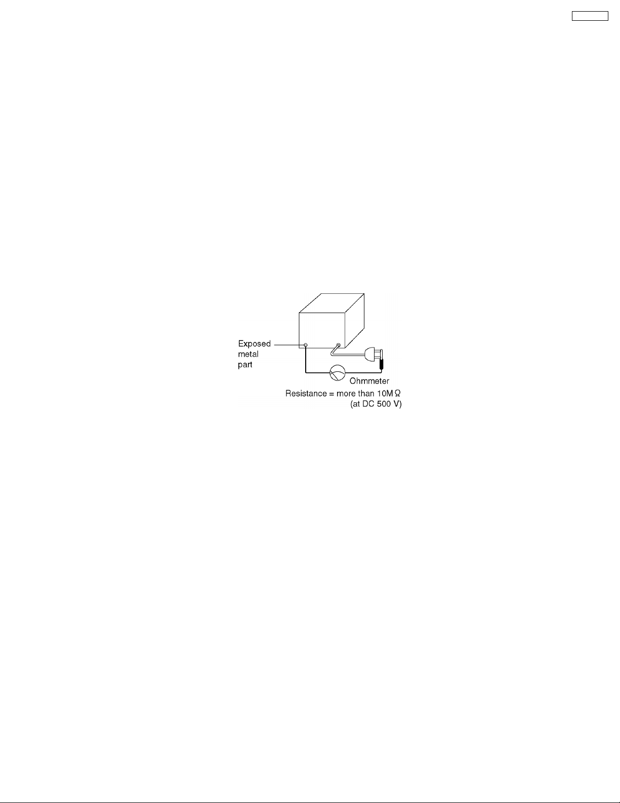
1.2. INSULATION RESISTANCE TEST
1. Unplug the power cord and short the two prongs of the plug with a jumper wire.
2. Turn on the power switch.
3. Measure the resistance value with an ohmmeter between the jumpered AC plug and each exposed metal cabinet part (screw
heads, control shafts, bottom frame, etc.).
Note: Some exposed parts may be isolated from the chassis by design. These will read infinity.
4. If the measurement is outside the specified limits, there is a possibility of a shock hazard.
The equipment should be repaired and rechecked before it is returned to the customer.
1.3. FOR SERVICE TECHNICIANS
ICs and LSIs are vulnerable to static electricity.
When repairing, the following precautions will help prevent recurring malfunctions.
1. Cover the plastic part´s boxes with aluminum foil.
2. Ground the soldering irons.
3. Use a conductive mat on the worktable.
4. Do not touch the IC or LSI pins with bare fingers.
1.4. BATTERY CAUTION
CAUTION
Danger of explosion if battery is incorrectly replaced.
Replace only with the same or equivalent type recommended by the manufacture. Dispose of used batteries according to the
manufacturer´s instructions.
3
KX-FT21RS
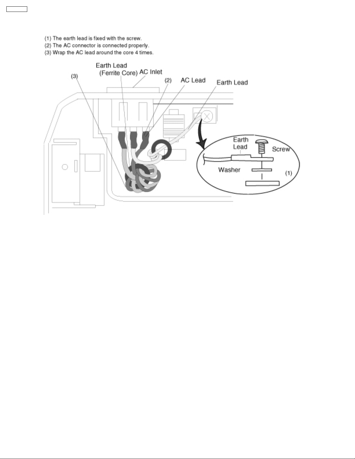
1.5. AC CAUTION
For safety, before closing the lower cabinet, please make sure of the following precautions.
4
KX-FT21RS
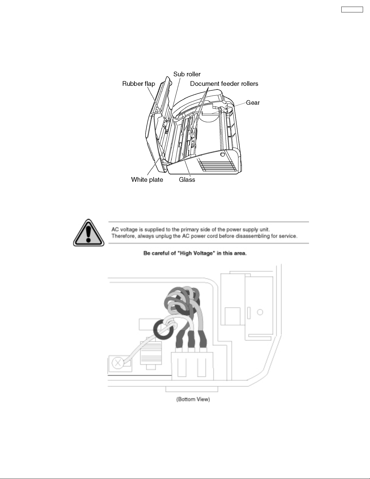
1.6. PERSONAL SAFETY PRECAUTIONS
1.6.1. MOVING SECTIONS OF THE UNIT
Be careful not to let your hair, clothes, fingers, accessories, etc., become caught in any moving sections of the unit.
The moving sections of the unit are the rollers and a gear. There is a separation roller and a document feed roller which are rotated
by the document feed motor. A gear rotates the two rollers. Be careful not to touch them with your hands, especially when the unit
is operating.
1.6.2. LIVE ELECTRICAL SECTIONS
All the electrical sections of the unit supplied with AC power by the AC power cord are live.
Never disassemble the unit for service with the AC power supply plugged in.
(Bottom view)
5

KX-FT21RS
1.7. FEATURES
General
· Desktop type
· LCD (Liquid Crystal Display) readout
· Help function
· Copier function
Facsimile
· Space Saving Compact Design
· Resolution: standard/fine/super fine/halftone
· Copier Function
· Automatic Document Feeder (10 Sheets)
· Help Printout
· Easy-to-view LCD (15 Characters)
Integrated telephone system
· Electric Volume Control
· On-hook dialing
· Redialing function
· Temporary tone dialing
· Electric telephone directory
6
KX-FT21RS
1.8. SPECIFICATIONS
Applicable Lines: Public Switched Telephone Network
Document Size: Max. 216 mm (8 1/2”) in width
Max. 600 mm (23 5/8”) in length
Effective Scanning Width: 208mm (8 3/16”)
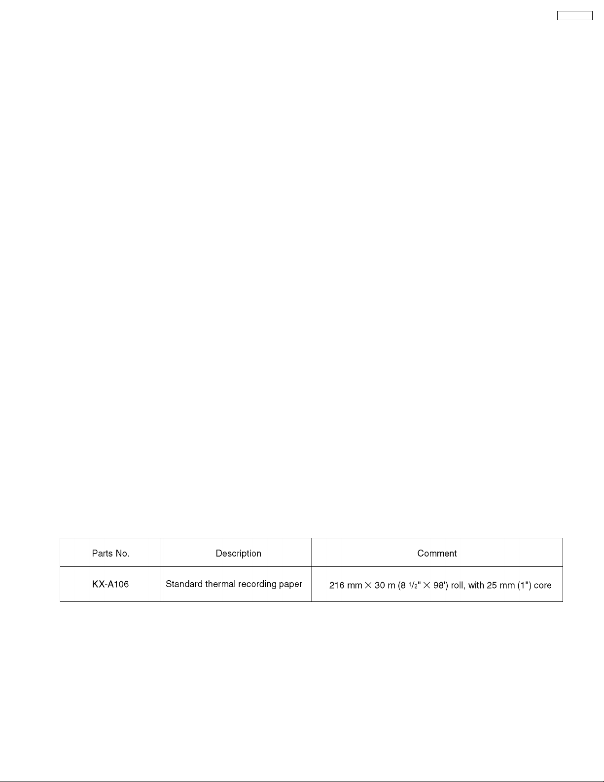
Recording Paper Size: 216 mm max. 30 m (8 1/2”×98”) roll
Effective Printing Width: 208 mm (8 3/16”)
Transmission Time*: Approx. 15 s/page (Original mode)**
Approx. 30 s/page (G3 Normal mode)
Scanning Density: Horizontal:
8 pels/mm (203 pels/inch)
Vertical:
3.85 lines/mm (98 lines/inch)—STANDARD mode
7.7 lines/mm (196 lines/inch)—FINE/HALF TONE mode
15.4 lines/mm (392 lines/inch)—SUPER FINE mode
Halftone Level: 64-level
Scanner Type: Contact Image Sensor (CIS)
Printer Type: Thermal Printing
Data Compression System: Modified Huffman (MH), Modified READ (MR)
Modem Speed: 9,600 / 7,200 / 4,800 / 2,400 bps; Automatic Fallback
Operating Environment: 5°C—35°C (41°F—95°F), 45 %—85 % RH (Relative Humidity)
Dimensions (H×W×D): 122 mm × 338 mm × 240 mm (4 13/16” × 13 5/16” × 9 7/16”)
Mass (Weight): Approx. 2.5 kg (5.5 lb.)
Power Consumption: Standby: Approx. 5.5 W
Transmission: Approx. 17 W
Reception: Approx. 30 W (When receiving the CCITT No. 1 Test Chart)
Copy: Approx. 30 W (When copying the CCITT No. 1 Test Chart)
Maximum: Approx. 120 W (When copying a 100 % black document)
Power Supply: 220—240 V AC, 50/60 Hz
* Transmission speed depends upon the contents of the pages, resolution, telephone line conditions and capability of the other
party´s machine.
** The 15 second speed is based upon the CCITT No. 1 Test Chart.
Note:
· Any details given in these instructions are subject to change without notice.
· The pictures and illustrations in these instructions may vary slightly from the actual product.
1.9. OPTIONAL ACCESSORIES
7

KX-FT21RS
1.10. CCITT No. 1 TEST CHART
8
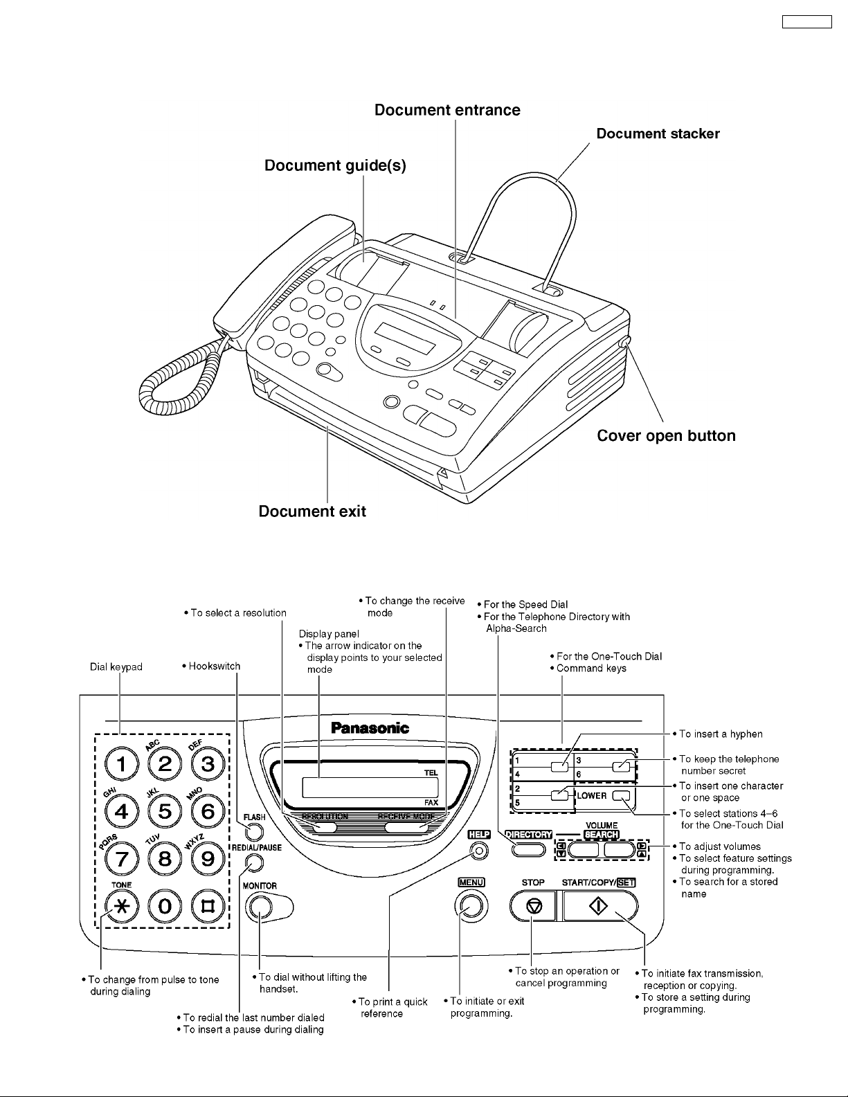
1.11. LOCATION OF CONTROLS
1.11.1. OVERVIEW
KX-FT21RS
1.11.2. CONTROL PANEL
9
KX-FT21RS
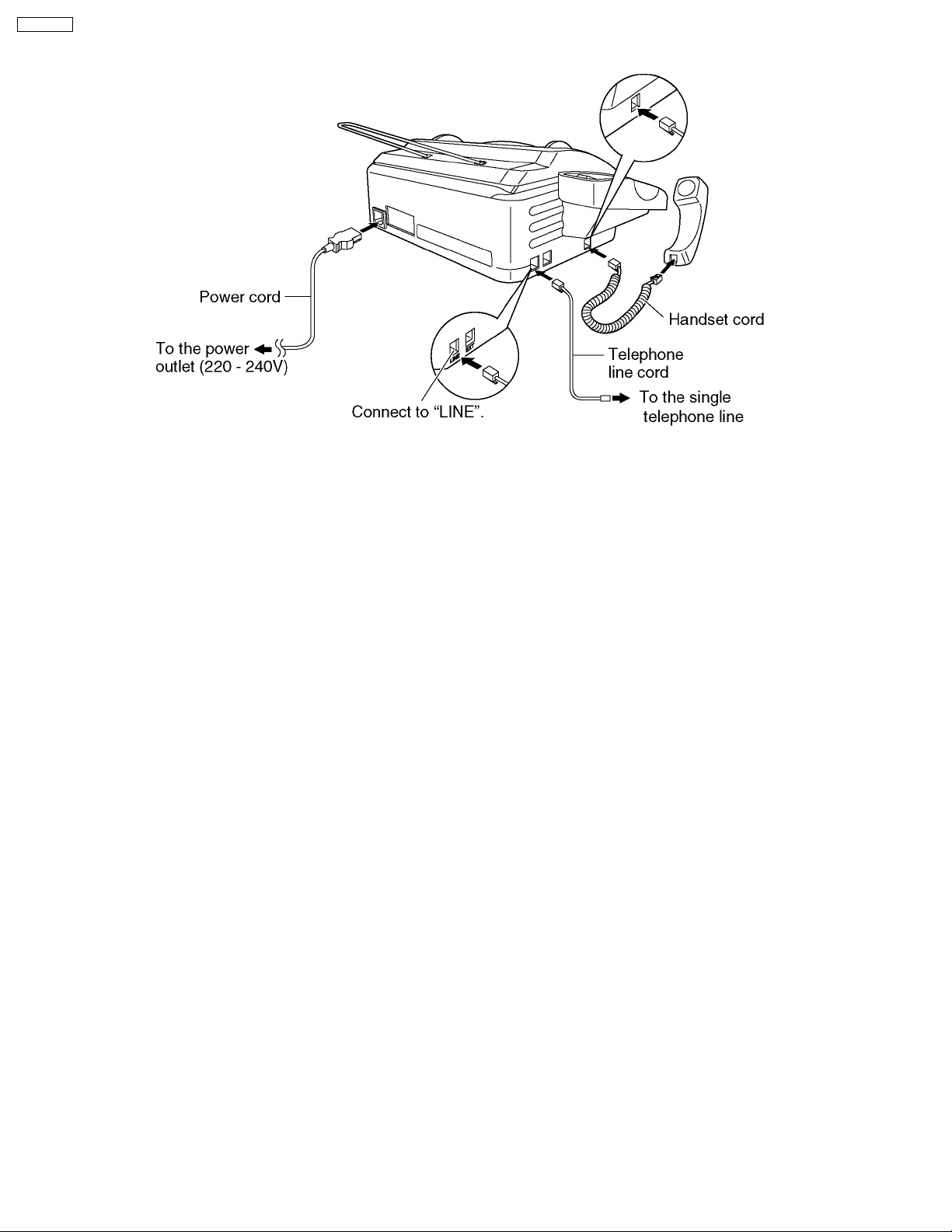
1.12. CONNECTIONS
NOTE
When you operate this products, the power outlet should be near the product and easily accessible.
10
1.13. INSTALLATION
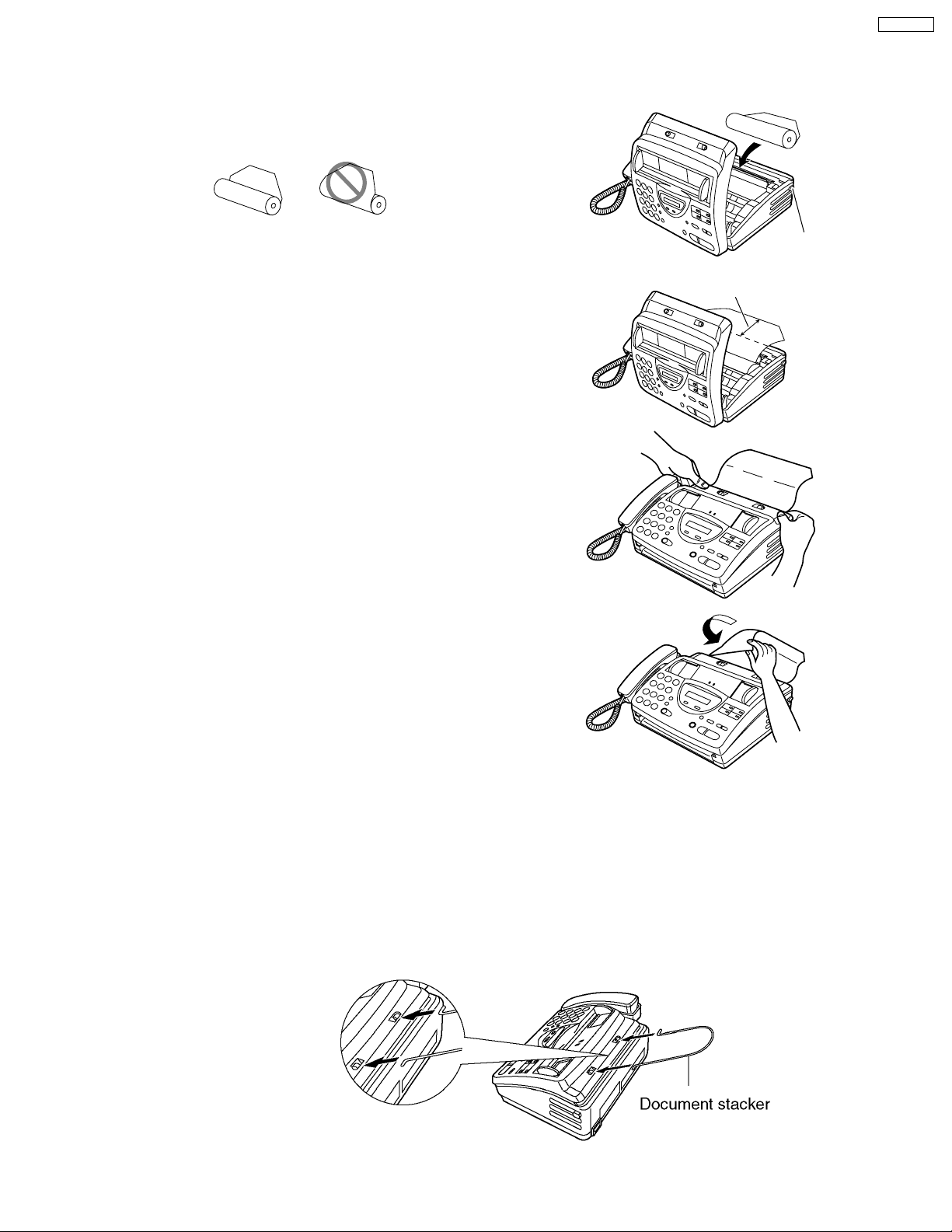
1.13.1. INSTALLING THE RECORDING PAPER
Open the cover by pressing the cover open button
1
and install the recording paper roll.
KX-FT21RS
correct
If the paper is secured with glue or tape, cut
approximately 15 cm (6 inches) from the
beginning.
Pull the leading edge of the paper approximately
10 cm (4 inches) out of the unit.
2
Make sure that there is no slack in the
paper roll.
Close the cover securely by pushing down on
3
4
both ends.
Tear off the excess paper by pulling it
towards you.
incorrect
Cover open
button
10 cm
Note:
Only use the included roll of paper or specified recording paper, or else the print quality may be affected and/or excessive
thermal head wear may occur.
For accessory order information.
When the power cord is connected, every time you close the cover a message will be printed. If the recording paper is set to
the wrong side, the message will not be printed. Install the paper correctly.
1.13.2. Document Stacker
Install the document stacker.
11
KX-FT21RS
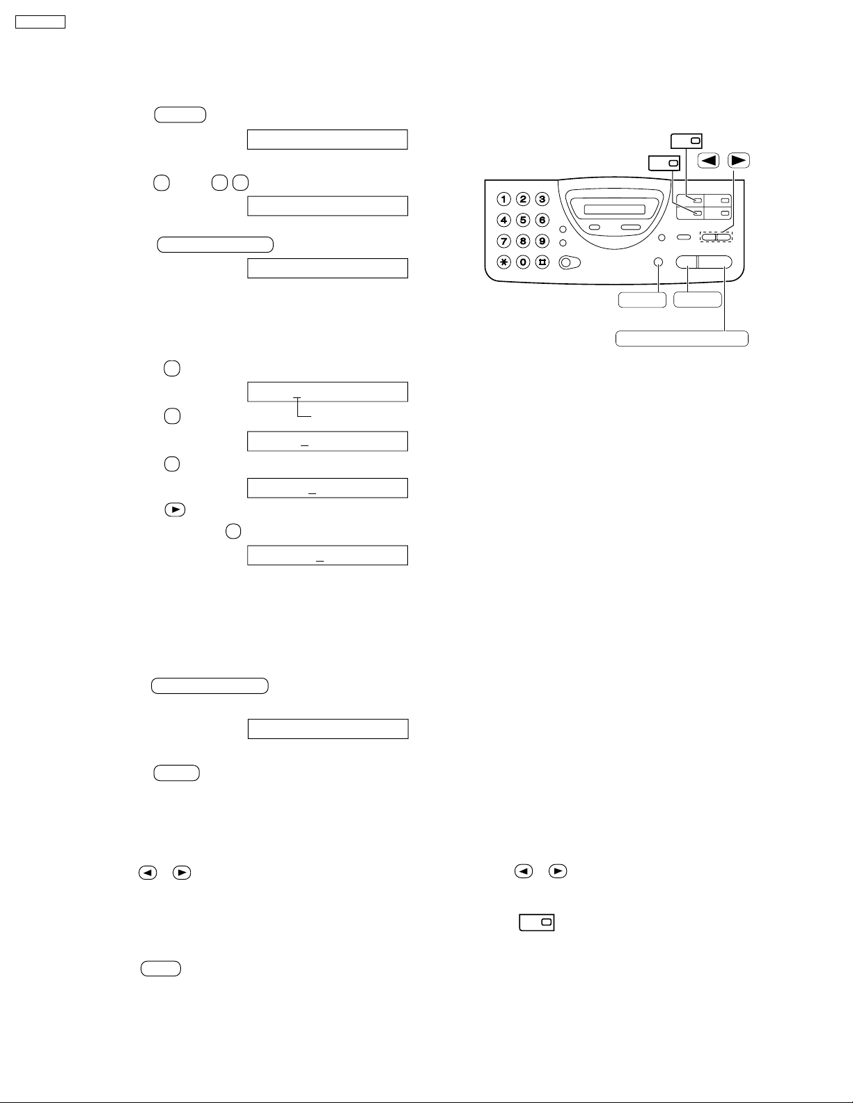
1.13.3. SETTING YOUR LOGO
The logo can be your company, division or name.
Press MENU .
1
Display: SYSTEM SET UP
Press # , then 0 2 .
2
Press START/COPY/SET .
3
YOUR LOGO
LOGO=
1
2
/
Enter your logo, up to 30 characters, by using
4
the dial keypad. See the next page for details.
Example: Bill
1. Press 2 twice.
LOGO=
2. Press 4 six times.
LOGO=B
3. Press 5 six times.
LOGO=Bi
4. Press to move the cursor to the next
space and press 5 six times.
LOGO=Bil
To enter the same number key continuously ,
move the cursor to the next space.
Press START/COPY/SET .
5
B
i
Cursor
l
l
MENU
START/COPY/SET
STOP
(Delete)
SETUP ITEM [ ]
Press MENU .
6
T o correct a mistake
Press or to move the cursor to the incorrect
character, then make the correction.
T o delete a character
Move the cursor to the character you want to delete and
press STOP .
Note:
Words in blankets ( ) are Spanish. A translated version for each market is available with this
model series.
12
To insert a character
1. Press or to move the cursor to the
position to the right of where you want to
insert the character.
2. Press (One-Touch Dial key 2) to insert a
2
space and enter the character.
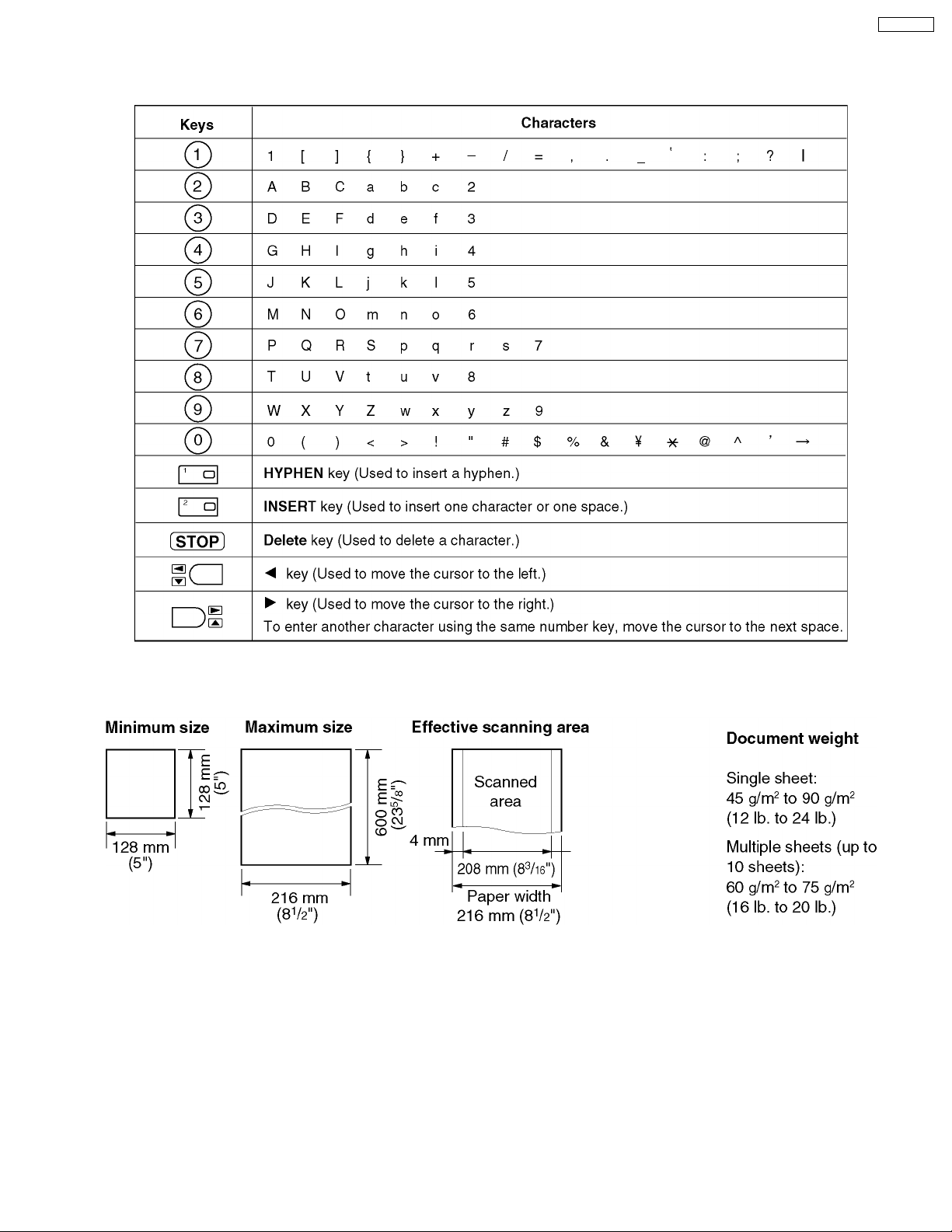
1.13.4. To select characters with the dial keypad
Pressing the dial keys will select a character as shown below.
KX-FT21RS
1.13.5. Documents you can send
Note:
Remove clips, staples or other similar fastening objects.
Check that ink, paste or correction fluid has dried.
Do not send the following types of documents. Use copies for fax transmission.
· Chemically treated paper such as carbon or carbonless duplicating paper
· Electrostatically charged paper
· Heavily curled, creased or torn paper
· Paper with a coated surface
· Paper with a faint image
· Paper with printing on the opposite side that can be seen through the front (e.g. newspaper)
13
KX-FT21RS
1.14. MAINTENANCE ITEMS AND COMPONENT LOCATIONS
1.14.1. OUTLINE
MAINTENANCE AND REPAIRS ARE PERFORMED USING THE FOLLOWING STEPS.
1. Periodic maintenance
Inspect the equipment periodically and if necessary, clean any contaminated parts.
2. Check for breakdowns
Look for problems and consider how they arose.
If the equipment can be still used, perform copying, self testing or communication testing.
3. Check equipment
Perform copying, self testing and communication testing to determine if the problem origina tes from the transmitter, receiver or
the telephone line.
4. Determine causes
Determine the causes of equipment problem by troubleshooting.
5. Equipment repairs
Repair or replace the defective parts and take appropriate measures at this stage to ensure that the problem will not recur.
6. Confirm normal operation of the equipment
After completing the repairs, conduct copying, self testing and communication testing to confirm that the equipment operates
normally.
7. Record keeping
Make a record of the measures taken to rectify the problem for future reference.
1.14.2. MAINTENANCE CHECK ITEMS/COMPONENT LOCATIONS
14
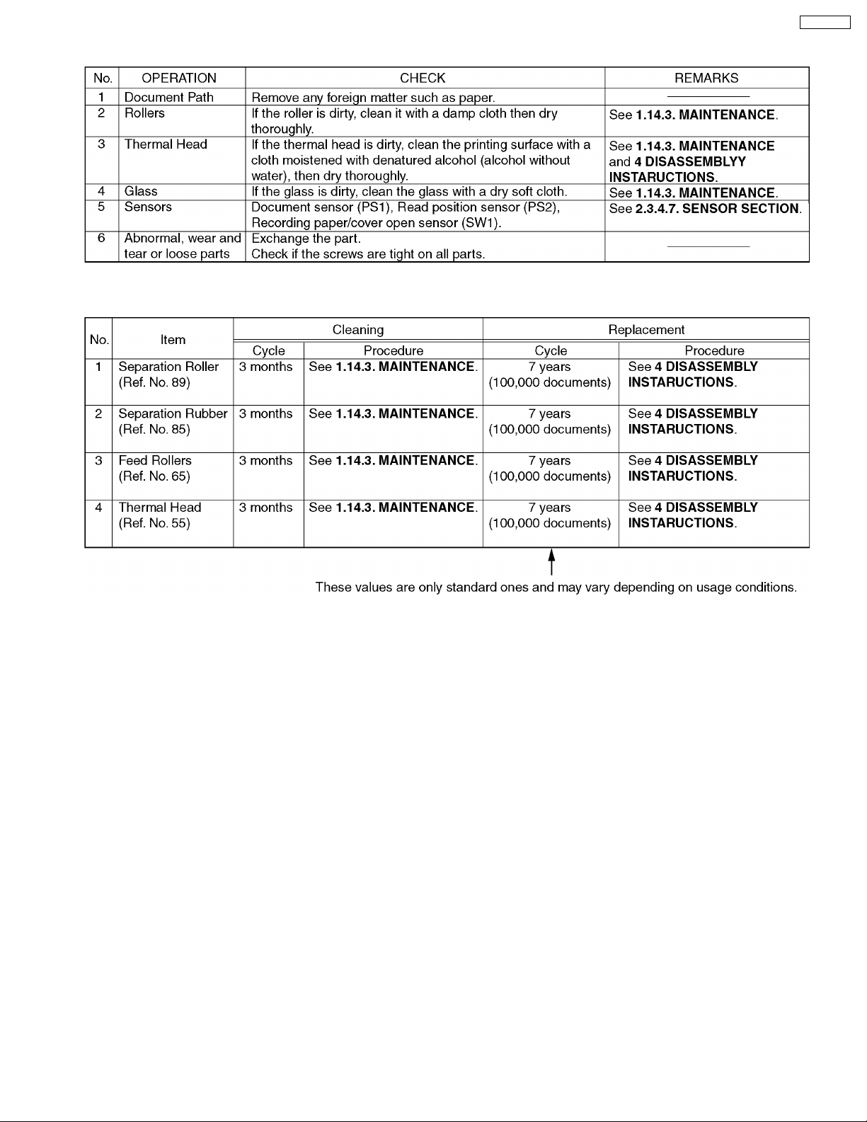
1.14.2.1. MAINTENANCE LIST
1.14.2.2. MAINTENANCE CYCLE
KX-FT21RS
15
KX-FT21RS
1.14.3. MAINTENANCE
1.14.3.1. CLEANING THE DOCUMENT FEEDER UNIT
If misfeeding occurs frequently or if dirty patterns or black bands appear on a copied or transmitted document, clean the document
feeder.
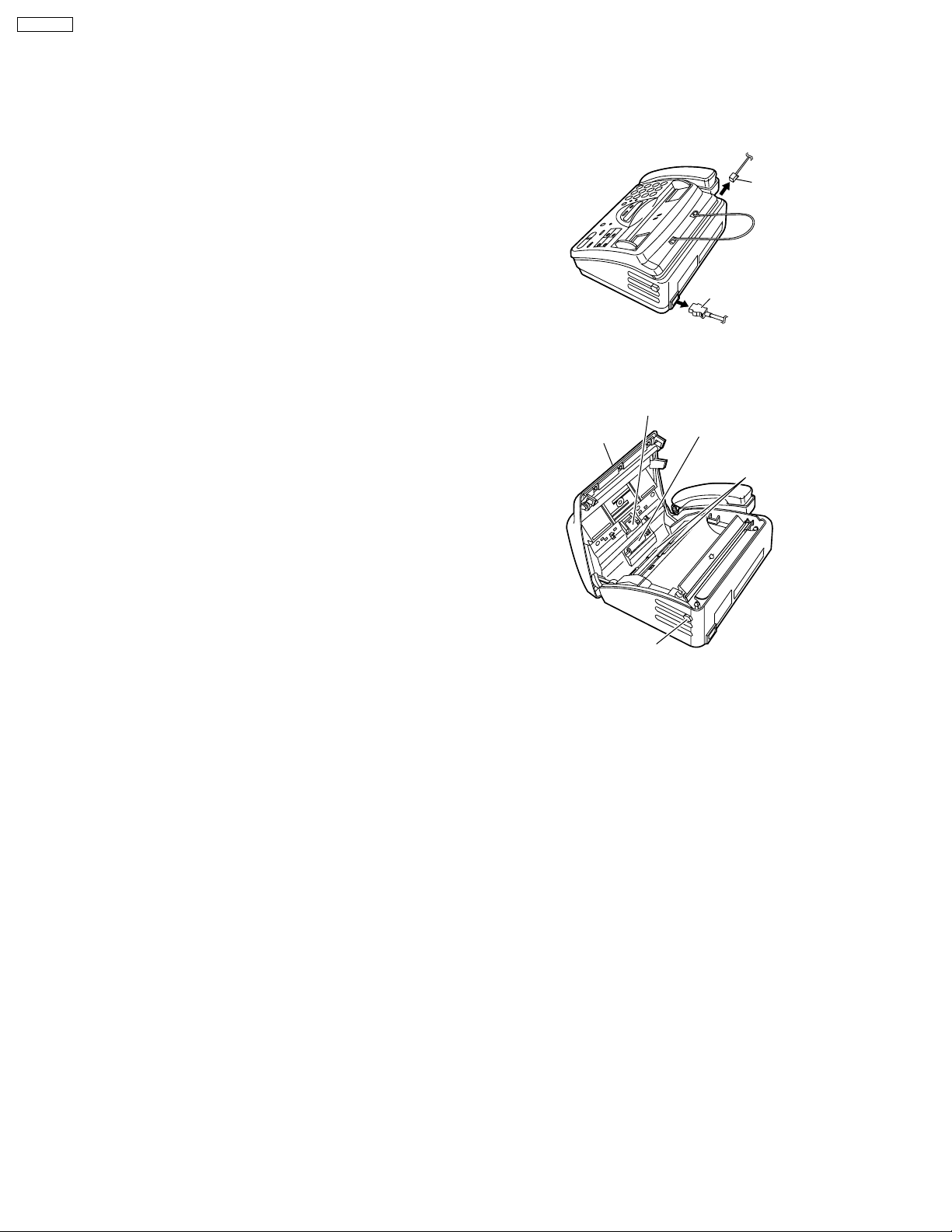
Disconnect the power cord and the telephone
1
line cord.
Open the cover by pressing the cover open button.
2
Clean the document feeder rollers, sub roller and
3
rubber flap with a cloth moistened with isopropyl
rubbing alcohol, and let all parts dry thoroughly.
Clean the white plate and glass with a soft dry cloth.
4
Close the cover securely by pushing down on both
5
6
Caution:
or tissues, to clean the inside of the unit.
ends.
Connect the power cord and the telephone line
cord.
Do not use paper products, such as paper towels
Separation roller
Cover
Cover open button
Telephone
line code
Power cord
Sub roller
Document
feeder rollers
16
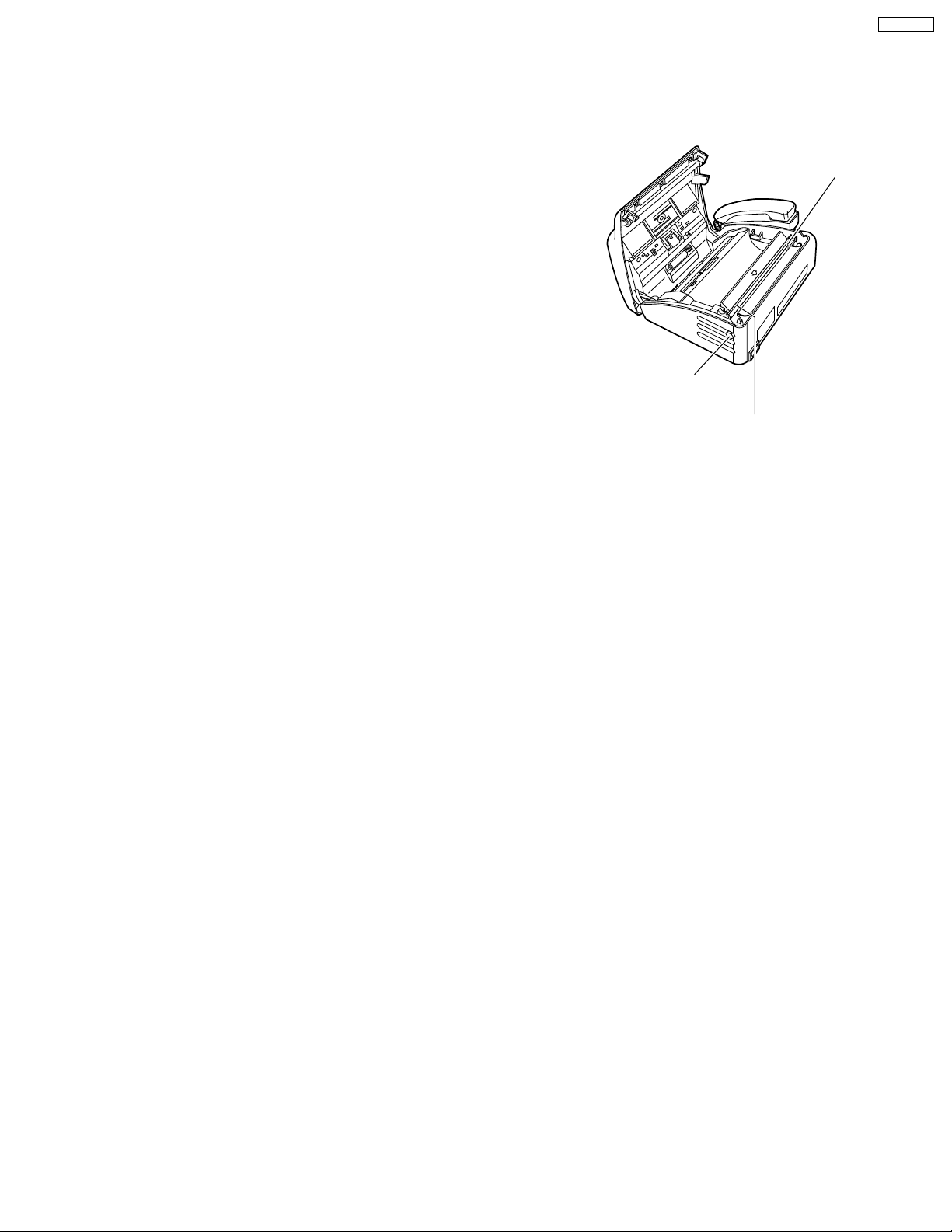
1.14.3.2. CLEANING THE THERMAL HEAD
If dirty patterns or black bands appear on a copied or received document, clean the thermal head.
Disconnect the power cord and the telephone
1
line cord.
KX-FT21RS
Open the cover by pressing the cover open button.
Thermal head
2
Clean the thermal head with a cloth moistened with
3
4
5
Caution:
a dry cloth and do not touch the thermal head directly with
your fingers.
1.14.3.3. CLEANING THE PICK UP ROLLER........Refer to 4 DISASSEMBLY INSTRUCTION
isopropyl rubbing alcohol, and let it dry thoroughly.
Close the cover securely by pushing down on both
ends.
Connect the power cord and the telephone line
cord.
To prevent a malfunction due to static electricity , do not use
Cover open
button
Caution:
Do not push on
the black cover
17
KX-FT21RS
2 TROUBLESHOOTING GUIDE
2.1. TROUBLESHOOTING SUMMARY
2.1.1. TROUBLESHOOTING
After confirming the problem by asking the user, troubleshoot according to the instructions and observe the following precautions.
2.1.2. PRECAUTIONS
1. If there is a problem with the print quality or the paper feed, first check if the installation space and the print paper meets the
specifications, the paper selection lever/paper thickness lever is set correctly, and the paper is set correctly without any slack.
2. Before troubleshooting, first check that the connectors and cables are connected correctly (not loose).
If the problem occurs randomly, check it very carefully.
3. When connecting the AC power cord with the unit case and checking the operation, exercise utmost care when handling electric
parts in order to avoid electric shocks and short-circuits.
4. After troubleshooting, double check that you have not forgotten any connectors, left any loose screws, etc.
5. Always test to verify that the unit is working normally.
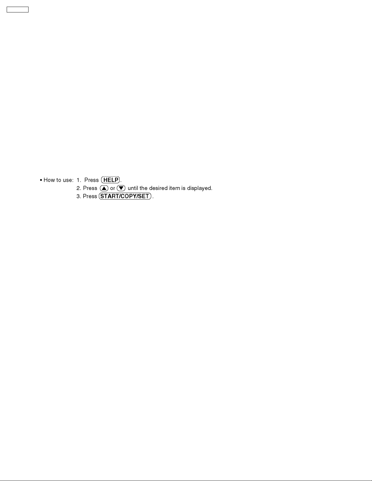
2.1.3. WHEN YOU DON´T KNOW HOW TO OPERATE THE UNIT, USE THE HELP
FUNCTION
18
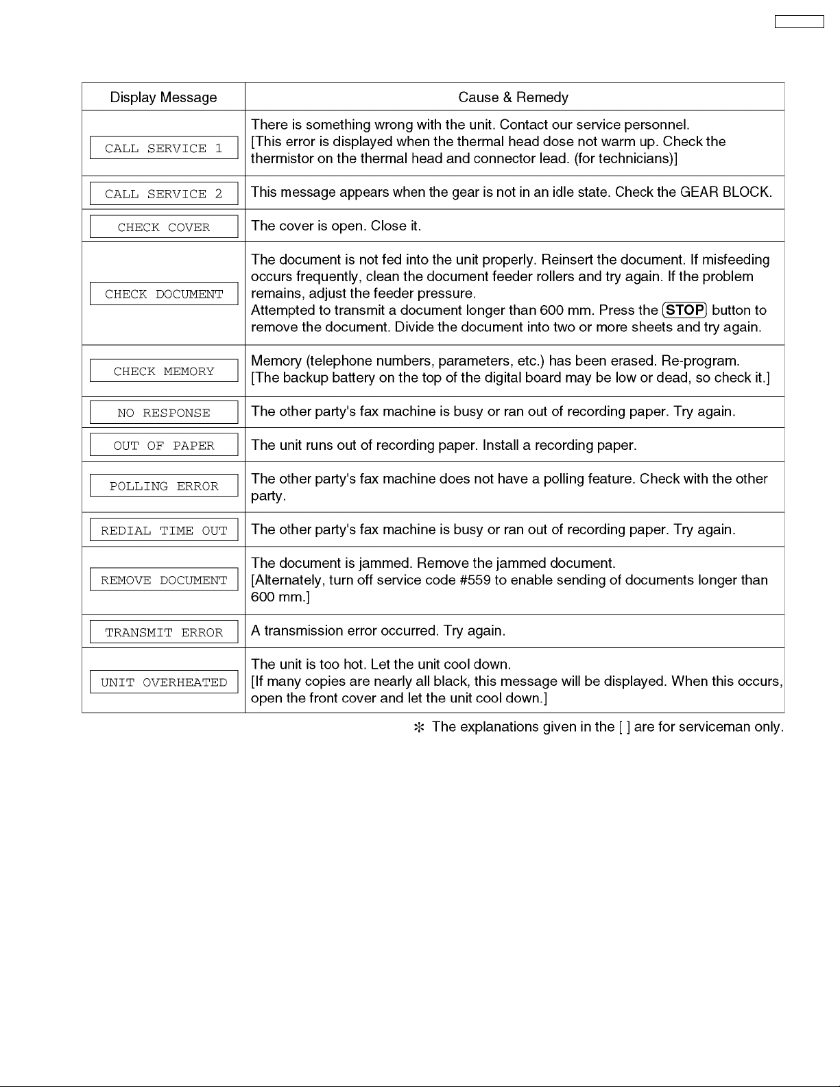
2.2. USER RECOVERABLE ERRORS
If the unit detects a problem, the following messages will appear on the display.
KX-FT21RS
Note:
The explanations given in the [ ] are for servicemen only.
19
KX-FT21RS
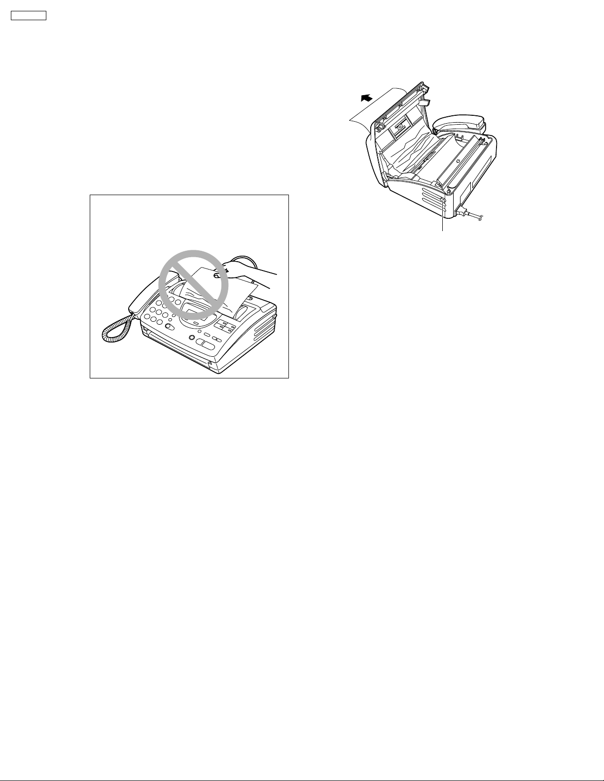
2.2.1. Document Jam
If the unit does not release the document during feeding, remove the jammed document as follows.
Open the cover by pressing the cover open
1
button.
Remove the jammed document carefully.
2
Close the cover securely by pushing down
3
on both ends.
Note:
• Do not pull out the jammed paper forcibly.
before opening the cover.
Cover open button
20
KX-FT21RS
2.3. TROUBLESHOOTING DETAILS
2.3.1. OUTLINE
Troubleshooting guide provides a logical path of deduction to assist in locating a fault and suggests methods of restoring the unit
to full working condition. Use the reported symptoms of the fault to determine the best troubleshooting method. Even difficult faults
can be tracked to a specific block or area, for example, the "Digital Board" or "Image Sensor".
A variety of fault descriptions from customers often point to the same area and, for this reason, careful analysis of the reported
symptoms is required. After every repair, test all functions to ensure no problems are evident.
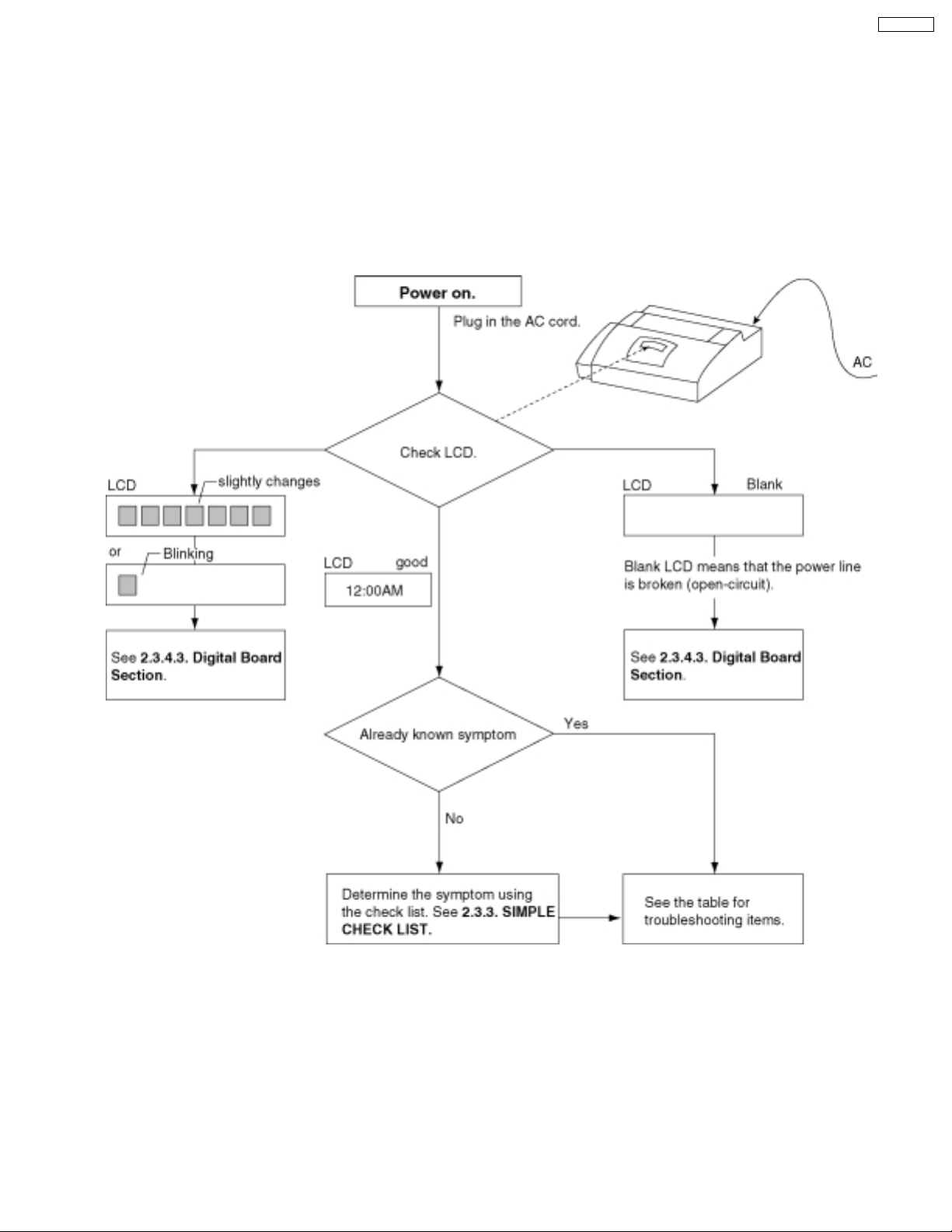
2.3.2. STARTING TROUBLESHOOTING
Select the appropriate troubleshooting method according to the symptoms.
21
KX-FT21RS
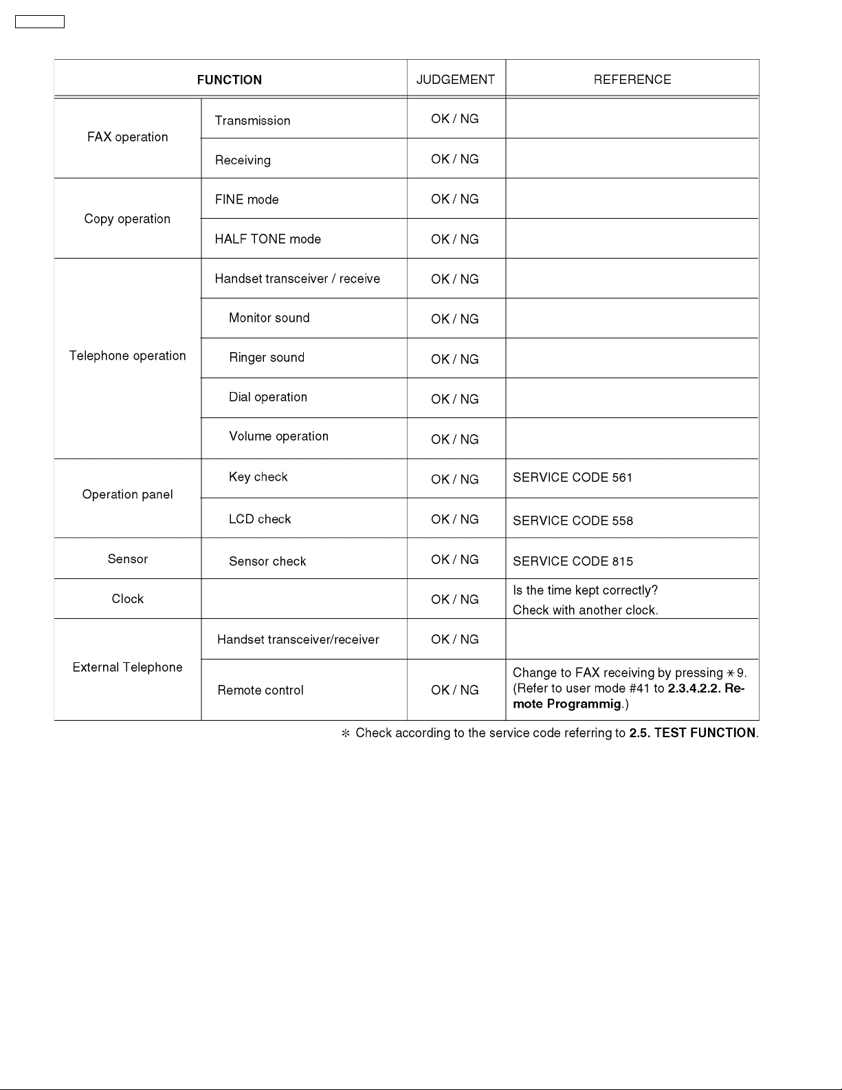
2.3.3. Simple Check List
22
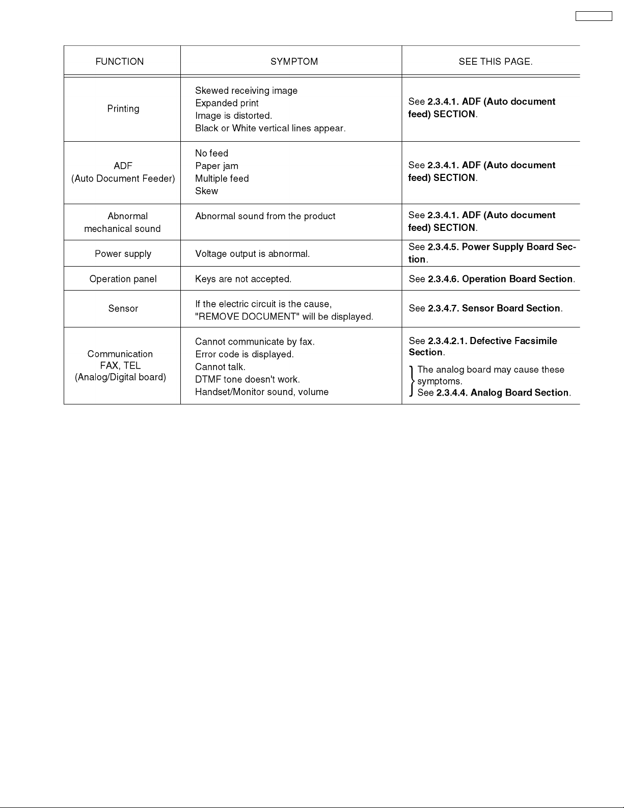
2.3.4. TROUBLESHOOTING ITEMS TABLE
KX-FT21RS
23
KX-FT21RS
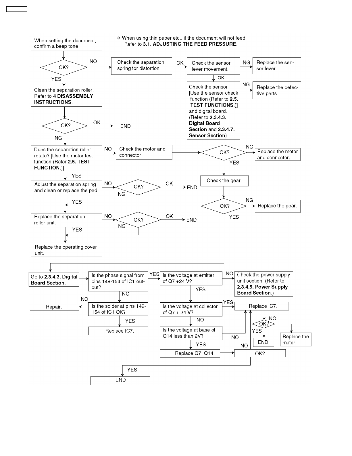
2.3.4.1. ADF (Auto Document Feed) Section
1. No document feed
24
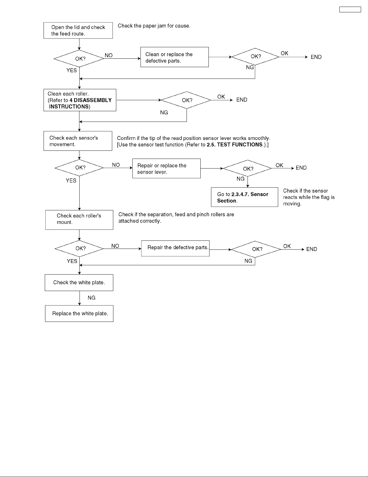
2. Paper JAM
KX-FT21RS
25
KX-FT21RS
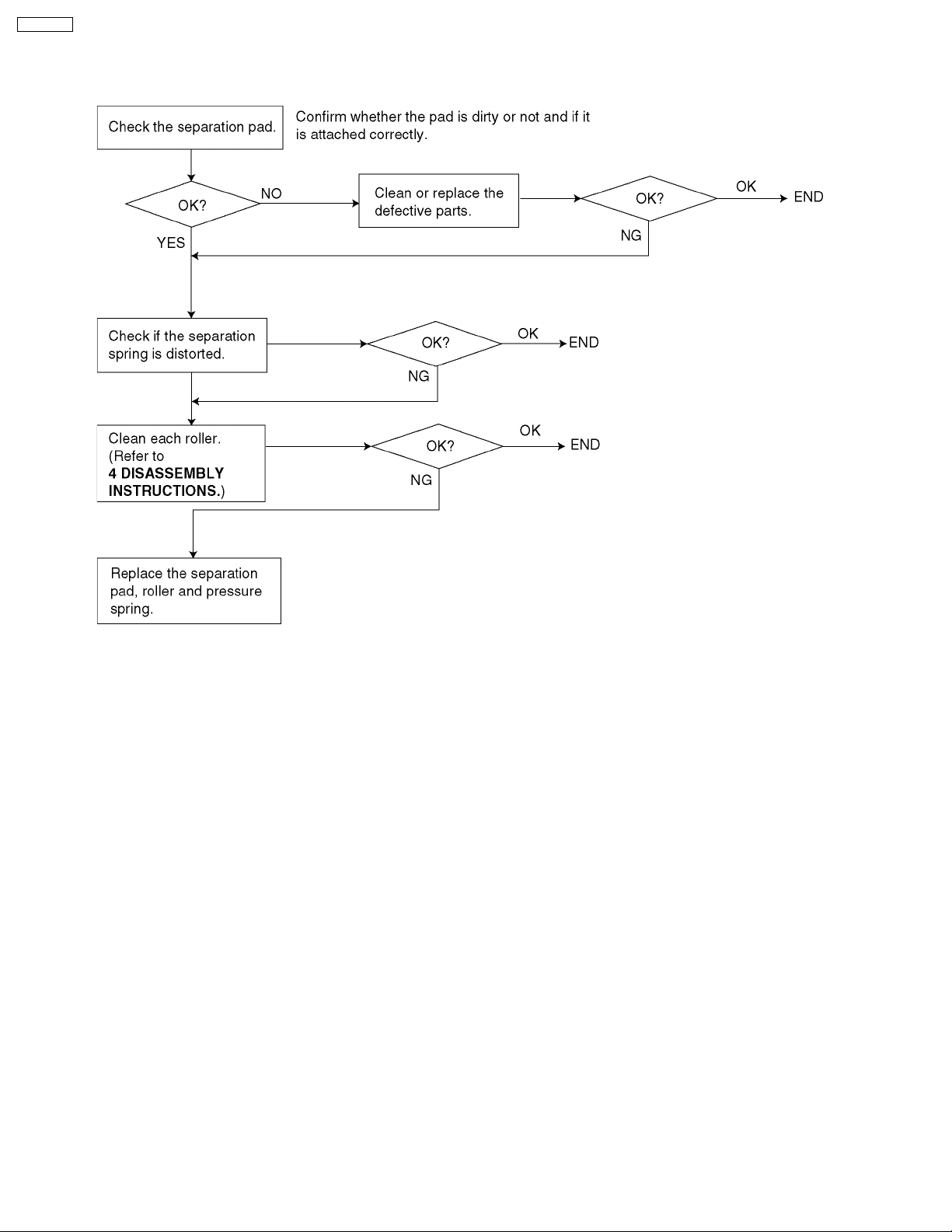
3. Multiple feed
When using thick paper etc., If the document will not feed.
Refer to 3.1. ADJUSTING THE FEED PRESSURE.
26
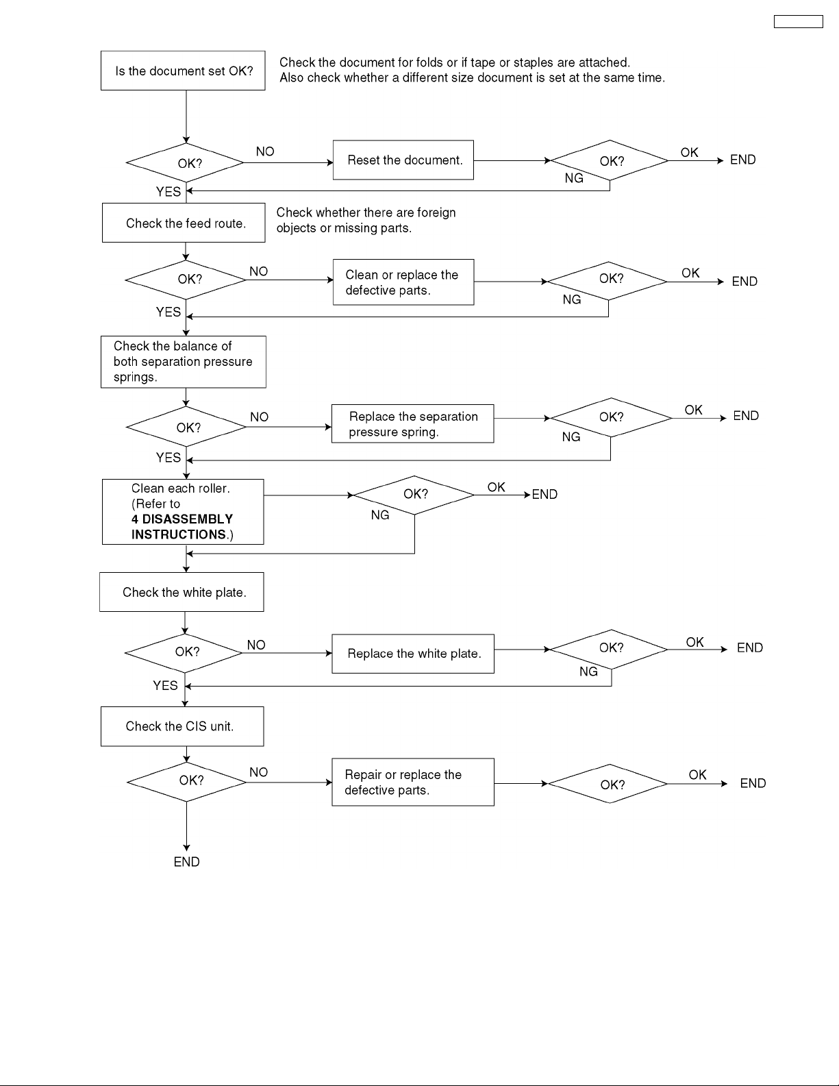
4. Skew
KX-FT21RS
27
KX-FT21RS
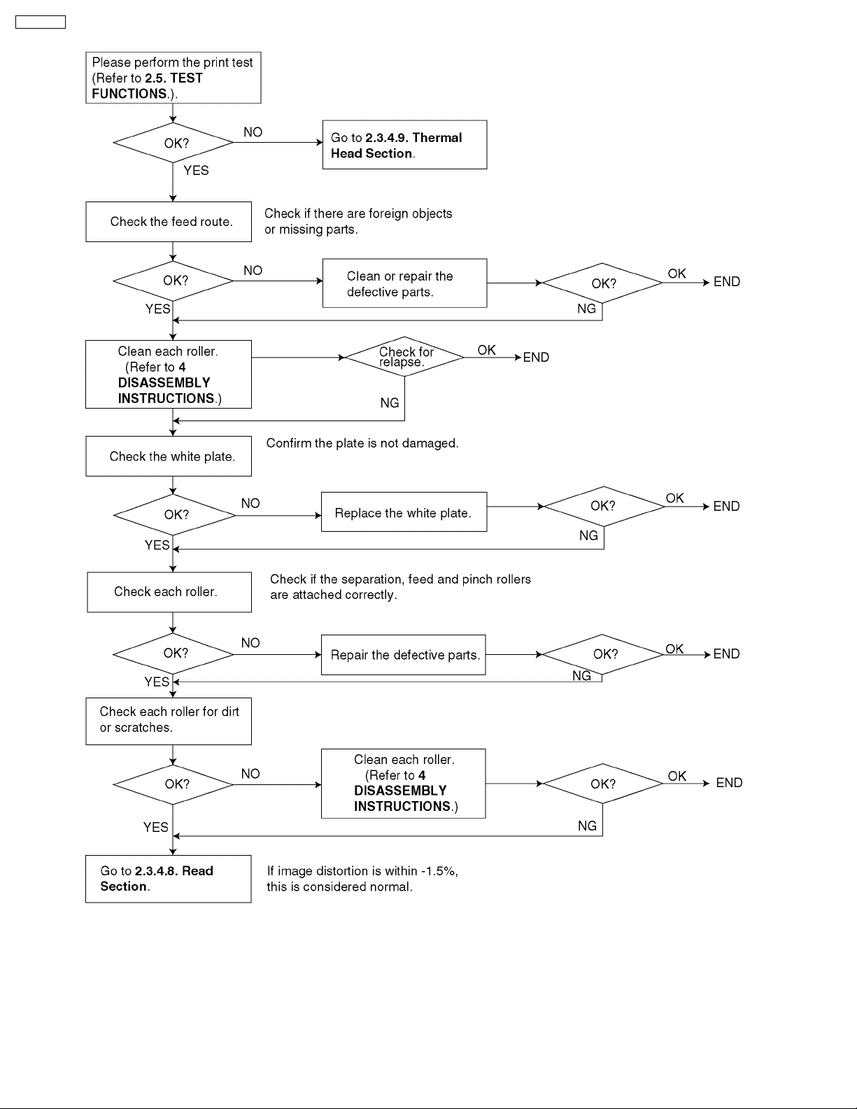
5. Image is distorted (When printing)
28
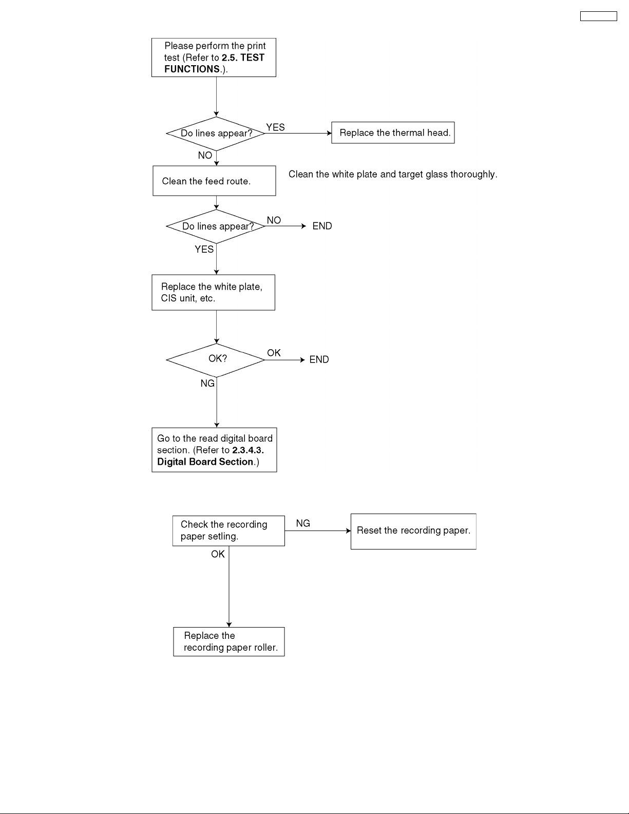
6. Black or white vertical lines appear
KX-FT21RS
7. Skewed receiving image
29
KX-FT21RS
8. Expander print (When printing)
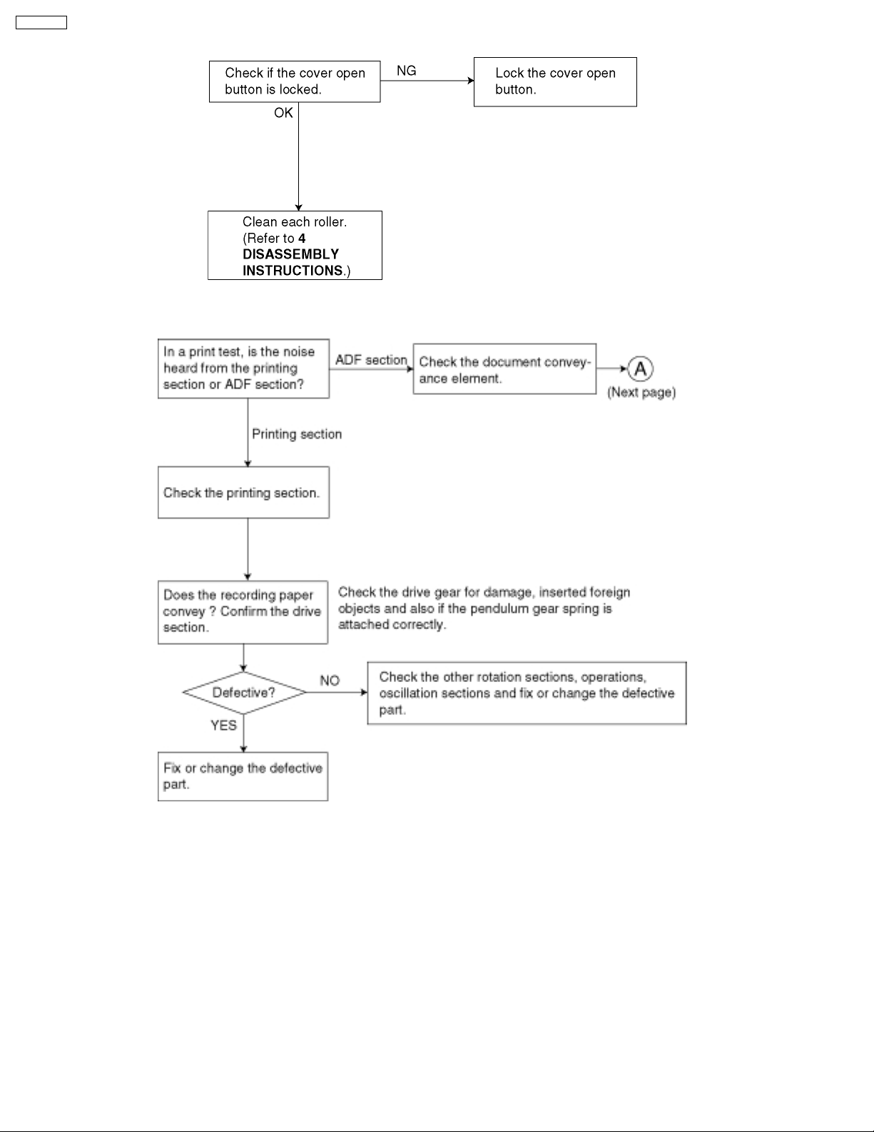
9. When copying or printing, an abnormal sound is heard from the unit
30
 Loading...