

Panasonic KX-FP105RS Service manual
Compact Plain Paper FAX
KX-FP105RS
(for Russia)
ORDER NO. KMF0002387A3
Please file and use this manual together with the service manual for Model No. KX-FP101AL, Order
No.KM79909316C3. This Service Manual indicates the main differences between; Original KX-FP101AL
and KX-FP105RS.
© 2000 Kyushu Matsushita Electric Co., Ltd. All
rights reserved. Unauthorized copying and
distribution is a violation of law.
KX-FP105RS
1 INTRODUCTION
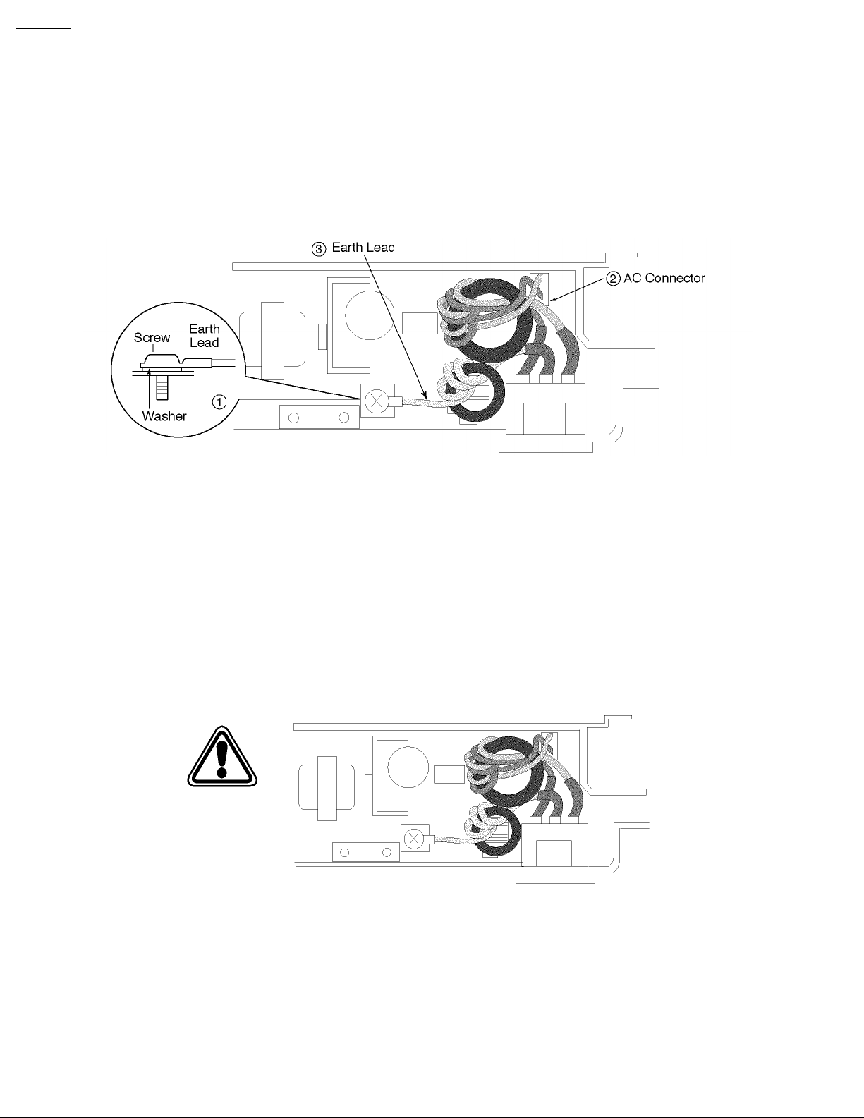
1.1. AC CAUTION
Change from original page 4 (1.5. AC CAUTION)
For safety, before closing the lower cabinet, please make sure of the following precautions.
1. The earth lead is fixed with the screw.
2. The AC connector is connected properly.
3. Wrap the earth lead around the core 3 times.
(Bottom View)
1.2. PERSONAL SAFETY PRECAUTIONS
1.2.1. LIVE ELECTRICAL SECTIONS
Change from original page 4 (1.6.2. LIVE ELECTRICAL SECTIONS)
All the electrical sections of the unit supplied with AC power by the AC power cord are live.
Never disassemble the unit for service with the AC power supply plugged in.
CAUTION:
AC voltage is supplied to the primary side of the power supply unit. Therefore, always unplug the AC power cord before
disassembling for service.
(Bottom View)
2

1.3. FEATURES
Change from original page 6 (1.8. FEATURES)
General
· Help function
Display:
1. HOW TO SET UP
2. EASY DIAL
3. FAX RECEIVING
· LCD (Liquid Crystal Display) readout
· TAM (Telephone answering machine) interface
Plain Paper Facsimile Machine
· 12 second transmission speed *
· A4, G3 compatible
· Automatic docum ent feeder (15 sheets)
· 6 stations one-touch dialer
· Broadcast (up to 20 station) × 3
· Resolution : Standard/Fine/Super fine/Half tone (64 level)
· LCD Contrast : Normal/Darker
· Delayed transmission
· Overseas transmission function
· Remote FAX receiving using an extension phone
· 150-sheet paper capacity
· Automatic fax/phone switching
· Distinctive ring detection **
* The 12 second speed is based upon the ITU-T Test Chart on
the condition that memory transmission is performed.
** Subscription to distinctive ring services required.
Large Memory (28 pages) ... Performed by DRAM
Approx. 28 pages of memory reception
Approx. 25 pages of memory transmission
Integrated Telephone System
· On-hook dialing
· Monitor
· Voice muting
· Redialing function
· 100-Station telephone directory with Easy Dial
Copier function
· Multi-copy function (up to 99 copies)
· Enlargement and reduction
· Collate
· 64-Level halftone
· Electronic film indicator
KX-FP105RS
3

KX-FP105RS
1.4. SPECIFICATIONS
Change from original page 7 (1.9. SPECIFICATIONS)
Applicable Lines: Public Switched Telephone Network
Document Size: Max. 216 mm (8 1/2") in width
Max. 600 mm (23 5/8") in length
Effective Scanning Width: 208 mm (8 3/16")
Recording Paper Size: A4: 210×297 mm (8 1/4"×11 11/16")
Effective Printing Width: 202 mm (7 15/16")
Transmission Time*: Approx. 12 sec./page (Original mode)**
Approx. 30 sec./page (G3 Normal mode)
Scanning Density: Horizontal:
8 pels/mm (203 pels/inch)
Vertical:
3.85 lines/mm (98 lines/inch)—STANDARD mode
7.7 lines/mm (196 lines/inch)—FINE/HALF TONE mode
15.4 lines/mm (392 lines/inch)—SUPER FINE Mode
Halftone Level: 64-level
Scanner Type: Contact Image Sensor (CIS)
Printer Type: Thermal Transfer Printing
Data Compression System: Modified Huffman (MH), Modified READ (MR), Modified Modified READ (MMR)
Modem Speed: 9,600/7,200/4,800/2,400 bps; Automatic Fallback
Operating Environment: 5—35°C (41—95°F), 20—80% RH(Relative Humidity)
Dimensions (H×W×D): 143×325×305 mm (5 5/8"×12 13/16"×12")
Mass (Weight): Approx. 4.0 kg (8.8 lb.)
Power Consumption: Standby: Approx. 6.5 W
Transmission: Approx. 15 W
Reception: Approx. 42 W (When receiving a 20% black document)
Copy: Approx. 45 W (When copying a 20% black document)
Maximum: Approx. 150 W (When copying a 100% black document)
Power Supply: 220—240 V AC, 50/60 Hz
Memory Capacity: Approx. 28 pages memory reception
Approx. 25 pages memory transmission
(Based on CCITT Test Chart in standard resolution, without using Error Correction
Mode.)
* Transmission speed depends upon the contents of the pages, resolution, telephone line conditions and capability of the receiving
unit.
** The 12 second speed is based upon the CCITT Test Chart and original mode. (Refer to "1.11. CCITT Test Chart".) If the
capability of the other party’s machine is inferior to your unit, the transmission time may be longer.
Note:
· Any details given in these instructions are subject to change without notice.
· The pictures and illustrations in these instructions may vary slightly from the actual product.
Design and specifications are subject to change without notice.
4
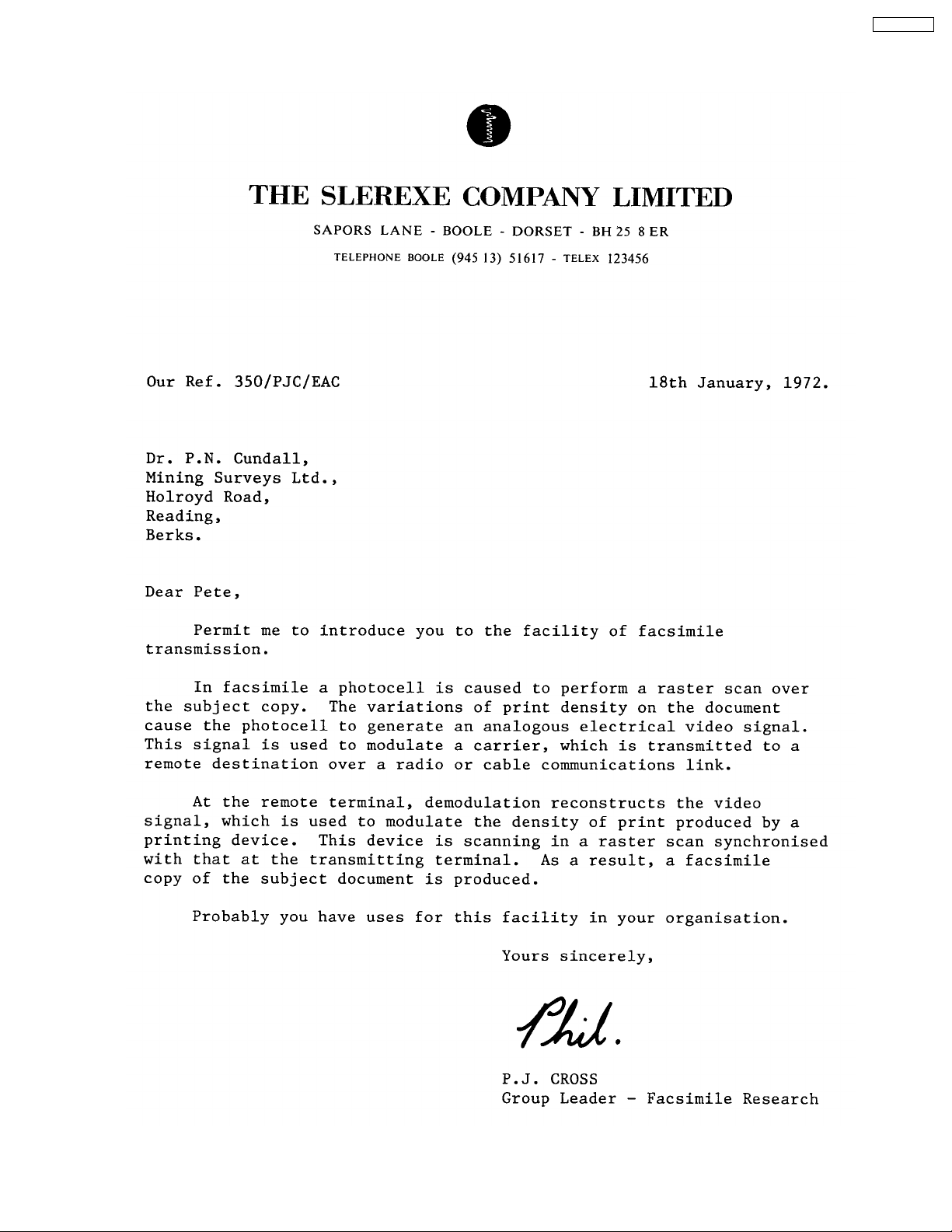
1.5. CCITT Test Chart
Change from original page 8 (1.11. ITU-T Test Chart (Actual size))
KX-FP105RS
5
KX-FP105RS
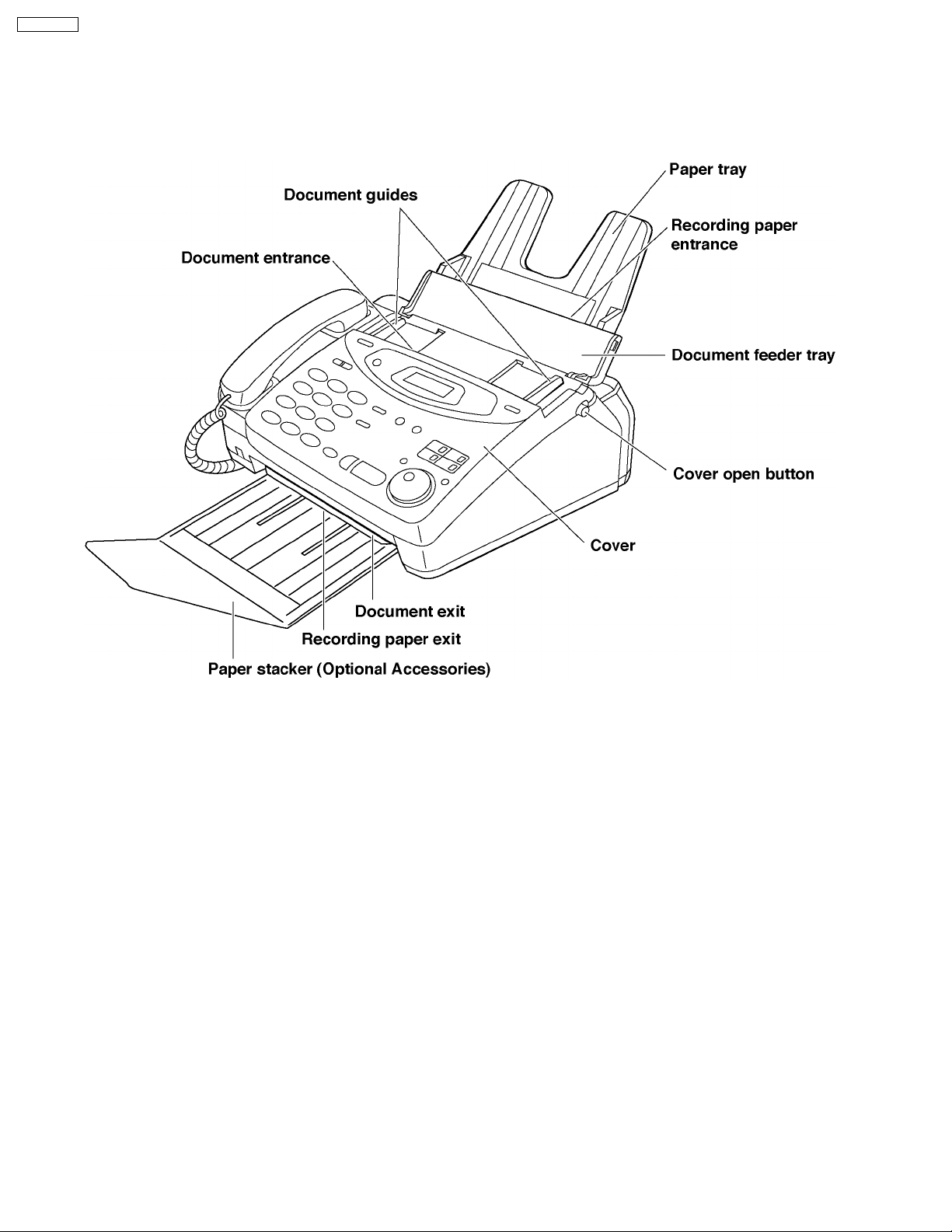
1.6. LOCATION OF CONTROLS
1.6.1. OVERVIEW
Change from original page 9 (1.12.1. OVERVIEW)
Note:
· The docum ent and recording paper will be ejected from the front of the unit. Do not put anything in front of the unit.
6
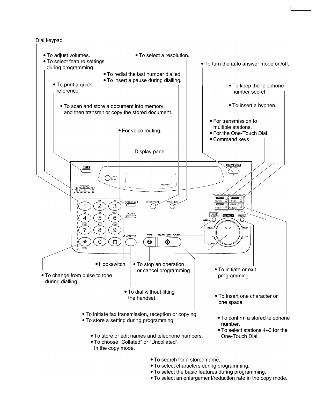
1.6.2. CONTROL PANEL
Change from original page 10 (1.12.2. CONTROL PANEL)
KX-FP105RS
7
KX-FP105RS
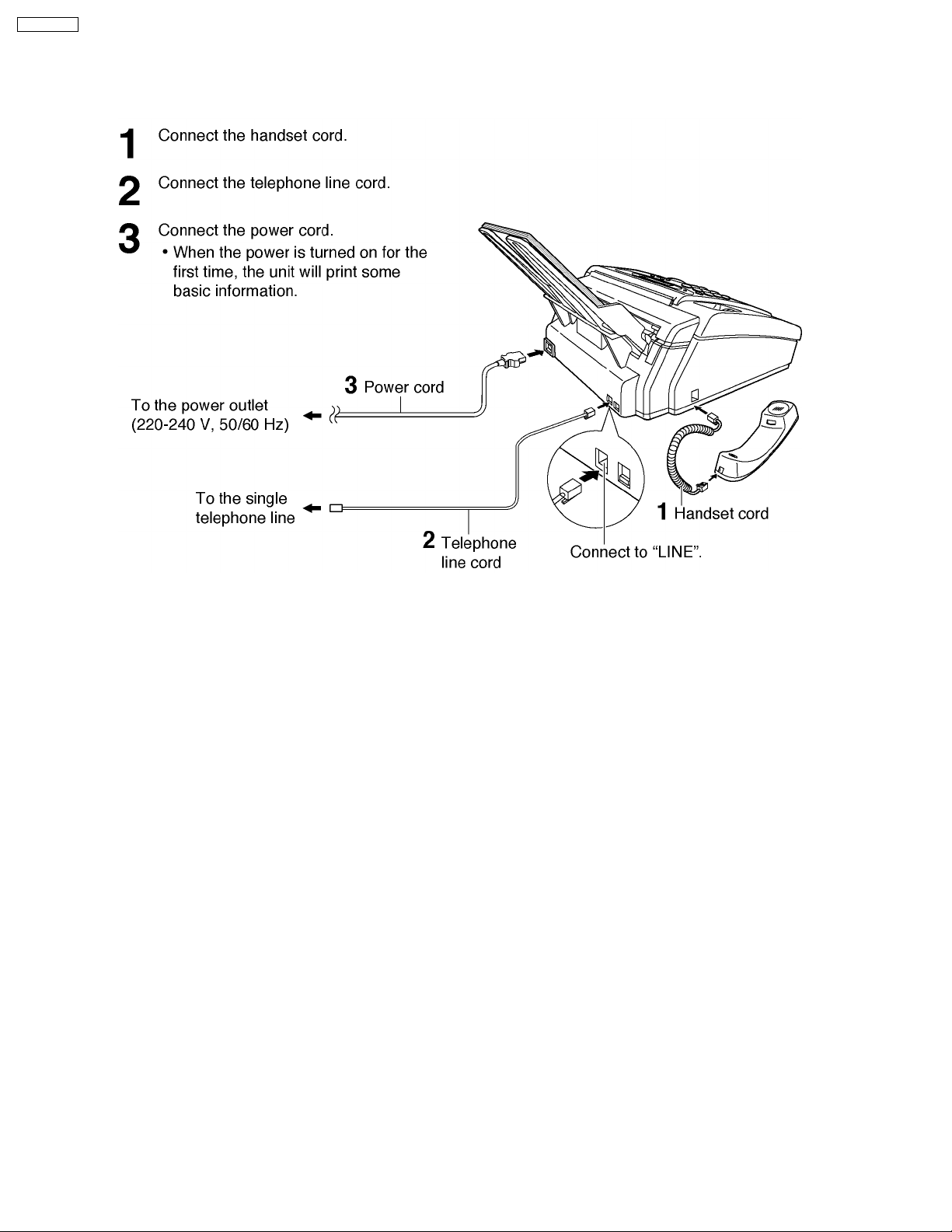
1.7. CONNECTIONS
Change from original page 11 (1.13. CONNECTIONS)
Note:
When you operate this product, the power outlet should be near the product and easily accessible.
8
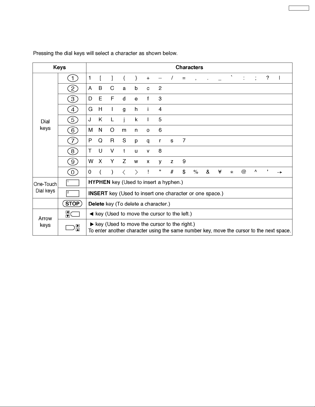
1.8. INSTALLATION
1.8.1. TO SELECT CHARACTERS WITH THE DIAL KEYPAD
Change from original page 18 (1.14.10. TO SELECT CHRACTERS WITH THE DIAL KEYPAD)
KX-FP105RS
Note: A hyphen entered in a telephone number is counted as two digits.
9

KX-FP105RS
2 TROUBLESHOOTING GUIDE
2.1. PROGRAM MODE TABLE
Change from original pages 60, 61 ([2. Program Mode Table] in 2.3.3.3.2. Remote programming)
2. Program Mode Table
Code Function Set Value Default Remote
001 Set date and time mm/dd/yy hh:mm Jan/01/99 NG
002 Your logo --------- None NG
003 Your telephone number --------- None NG
004 Transmission report mode 1:Error / 2:ON / 3:OFF Error OK
006 FAX ring count 1~5 1 OK
012 Remote TAM activation 1:ON / 2:OFF OFF ID=11 OK
013 Dialing mode 1:Pulse / 2:Tone Tone OK
018 Film remain --------- --------- NG
022 Auto journal print 1:ON / 2:OFF ON OK
023 Overseas mode ON / OFF OFF NG
025 Delayed transmission ON / OFF OFF NG
030 Silent FAX recognition ring 3 to 6 rings 3 OK
031 Distinctive ring 1:OFF / 2:A / 3:B / 4:C / 5:D OFF OK
036 Rx reduction 1:72% / 2:86% / 3:92% / 4:100% 92% OK
039 LCD contrast 1:Normal / 2:Darker Normal OK
040 Silent detection 1:ON / 2:OFF ON OK
041 Remote FAX activation code ON / OFF ON ID=*9 NG
044 Receive alert 1:ON / 2:OFF ON OK
046 Friendly receive 1:ON / 2:OFF ON OK
049 Auto disconnect ON / OFF ON NG
058 Original setting 1:Normal / 2:Light / 3:Darker Normal OK
068 ECM selection 1:ON / 2:OFF ON OK
070 FAX pager ON / OFF OFF NG
076 FAX tone 1:ON / 2:OFF ON OK
077 Auto answer mode 1:FAX Only 2:TEL/FAX FAX Only OK
078 TEL/FAX ring 1 to 4 rings 1 OK
079 Film detection 1:ON / 2:OFF ON OK
080 Set default YES / NO NO NG
501 Pause time set 001~600 x 100msec 050 OK
502 Flash time 01~99 x 10msec 070 OK
503 Dial speed 1:10pps / 2:20 pps 10pps OK
511 Vox sense 1:HIGH / 2:LOW HIGH OK
520 CED frequency select 1:2100Hz / 2:1100Hz 2100 OK
521 International mode select 1:ON / 2:OFF ON OK
522 Auto standby select 1:ON / 2:OFF ON OK
523 Receive equalizer select 1:0km / 2:1.8km / 3:3.6km / 4:7.2km 0km OK
524 Transmission equalizer select 1:0km / 2:1.8km / 3:3.6km / 4:7.2km 0km OK
550 Memory clear --------- --------- NG
551 ROM check --------- --------- NG
552 DTMF signal tone test ON / OFF OFF NG
553 Monitor on FAX communication 1:OFF / 2:Phase B / 3:ALL OFF OK
554 Modem test --------- --------- NG
555 Scanner test --------- --------- NG
556 Motor test --------- --------- NG
557 LED test --------- --------- NG
558 LCD test --------- --------- NG
559 Document jam detection 1:ON / 2:OFF ON OK
561 Key test --------- --------- NG
570 Break % select 1:61% / 2:67% 61% OK
571 ITS auto redial time set 00~99 14 OK
572 ITS auto redial line disconnection time set 001~999 30 OK
573 Remote turn-on ring number 01~99 15 OK
590 FAX auto redial time set 00~99 05 OK
591 FAX auto redial line disconnection time set 001~999sec 045 OK
592 CNG transmit select 1:OFF / 2:ALL / 3:AUTO ALL OK
593 Time between CED and 300 bps 1:75ms / 2:500ms / 3:1sec 75ms OK
594 Overseas DIS detection 1:1st / 2:2nd 1st OK
Setting
10

Code Function Set Value Default Remote
Setting
595 Receive error limit value 001~999 100 OK
596 Transmit level set -15~00dBm -10 OK
598 Receiving Sensitivity 20~48 43 OK
599 ECM frame size 1: 256 byte / 2: 64 byte 256 byte OK
602 Warning list printing 1:ON / 2:OFF ON OK
700 EXT. TAM OGM Rec. time 01~99sec 10sec OK
701 No voice detect time 01~99X100msec 50 OK
717 Transmit speed select 1:9600/ 2:7200/ 3:4800/ 4:2400 9600bps OK
718 Receive speed select 1:9600/ 2:7200/ 3:4800/ 4:2400 9600bps OK
719 Ringer off in TEL/FAX mode 1:ON / 2:OFF ON OK
721 Pause tone detect 1:ON / 2:OFF ON OK
722 Redial tone detect 1:ON / 2:OFF ON OK
745 Power on film feed 1:ON / 2:OFF ON OK
763 CNG detect time for friendly reception 1:10s / 2:20s / 3:30s 30s OK
771 T1 timer 1:35s / 2:60s 35s OK
774 T4 Timer 00~99 X100ms 00 OK
815 Sensor & VOX test --------- --------- NG
852 Print test pattern --------- --------- NG
853 Top margin 1~9 --------- OK
854 Left margin 1~8 --------- OK
861 A4 size set 1:ON / 2:OFF ON OK
880 History list 1:Start --------- NG
890 TEL/FAX ring back tone 1:ON / 2:OFF ON OK
991 Setup list 1:Start --------- OK
994 Journal list 1:Start --------- OK
995 Journal 2 list 1:Start --------- OK
996 Journal 3 list 1:Start --------- OK
998 History list 1:Start --------- OK
999 Service list 1:Start --------- OK
KX-FP105RS
OK means "can set".
NG means "can not set".
Note:
Refer to 2.4.4. SERVICE FUNCTION TABLE for descriptions of the individual codes.
Example:
If you want to set value in the "004 Transmission report mode", press the dial key number
Value you want to select. (1:ERROR/2:ON/3:OFF)
, or corresponding to the Set
11
remain normal. Other signal lines are not directly related to that failure even if they have faults or troubles.
You also need to check the signal lines listed here [List 1] when the unit fails to boot up the system. Those signal lines should
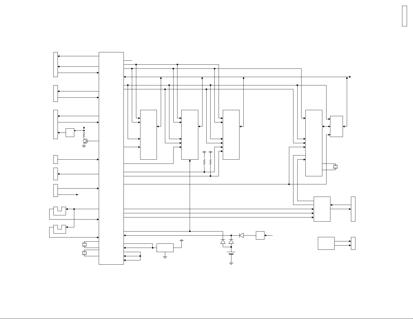
2.2. Digital Block Diagram
Change from original page 63 (2.3.3.4.1. Digital Block Diagram)
KX-FP105RS
12
TO
OP-PANEL
TO
CIS
TO
THRMAL
HEAD
TO
POSITIO
N
SW
TO
MOTOR
TO
POWER
SUPPLY
CN505
KSTART,KLATCH
KSCLK,KTXD
KRXD,JOG1,JOG2
CN504
F1,FTG
CISLEDON
VIDEO
CN508
THDAT,THCLK,THLAT
STB1,STB2,STB3
TM
+24V
CN507
CN506
TM[3:0],TXE
CN509
PDET
+24V,+5V,PG,DG
PS501
PS501
32.768KHz
24MHz
+24V
IC501
ASIC
OP-RESET
ADR[15:13]
SENSOR
LED ON
FILMEND
PAPER
TOP
XRESETI
XORESET
XBACKEN
RBA[6:0]
ADR[12:0]
DB[7:0]
XRD
XWR
XROMCS
XRAMCS
XRAS
XCAS
XMDMCS
MIDATA
MICLK
MILAT
+5V/BATT
+3V/BATT
XWDERR
XRESET
A[12:0]
RBA[5:0]
IC502
ROM
A[17:0]
XRD
XCS
D[7:0]
RESET-
IC
GND
A[11:0]
INOUT
RBA[2:0]
+5V
IC504
SRAM
A[16:0]
XRD
XWR
XCS
D[7:0]
VCC
+5V
A[7:4]
RBA[5:0]
IC503
DRAM
A[9:0]
XRD
XWR
XRAS
XCAS
D[7:0]
+
-
BATT
+3.3V
+5V
A[4:0]
A[4:0]
XRD
XWR
XCS
TX
RX
IC505
MODEM
D[7:0]
IC551
ANALOG ASIC
SP-AMP
IC550
DIR
BA
G
32.256MHz
CN501,502
TO
ANALOG
PCB
CN503
TO
SPEAKER
KX-FP105RS
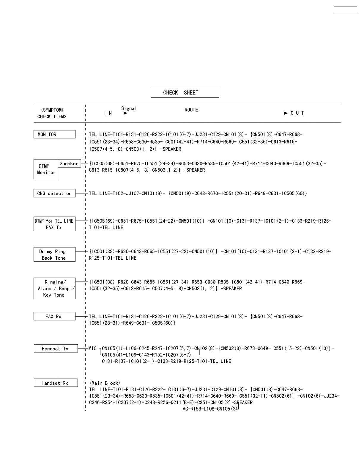
2.3. Analog Board Section
Change from original pages 71, 72 (2.3.3.5. Analog Board Section)
This chapter provides the testing procedures required for the analog parts. A signal route to be tested is determined depending
upon purposes. For example, the handset TX route begins at the handset microphone and the signal is output to the telephone line.
The signal mainly flowing on this route is analog. You can trace the signal with an oscilloscope. The signal flow on each route is
shown in the Check Sheet here. If you find a specific problem in the unit, for example if you cannot communicate with the H/S, trace
that signal route locally with the following Check Sheet and locate the faulty point.
Note:
{ }: Inside the digital board
13
 Loading...