

Page 1
Model No. KV-S2025C / KV-S2025CU / KV-S2026C / KV-S2026CU
KV-S2045C / KV-S2045CU / KV-S2046C / KV-S2046CU
KV-S2025C
KV-S2025CU
KV-S2026C
KV-S2026CU
KV-S2045C
KV-S2045CU
KV-S2046C
KV-S2046CU
These instructions contain information on operating the scanner. Before reading these
instructions, please read the installation manual enclosed with this unit.
Please carefully read these instructions, the enclosed installation manual and maintenance
manual. Keep all documentation in a safe place for future reference.
Keep the CD-ROM in the protective case. Do not expose the CD-ROM to direct sunlight or
extreme heat and do not scratch or smudge the surface of the CD-ROM.
Page 2

Thank you for purchasing a Panasonic “High Speed Color Scanner”.
≥ Panasonic supports your imaging needs with a reliable and easy-to-use document scanner.
≥ Panasonic has developed Panasonic Image Enhancement Technology to improve the quality of your scanned
images even beyond the quality of your original document.
∫ System requirements
When using the scanner , the required host computer conditions are as follows.
KV-S2025C / KV-S2045C
KV-S2026C SCSI Connection
KV-S2026C USB Connection
KV-S2046C USB Connection
KV-S2046C SCSI Connection
CPU
Minimum Pentium II, 300 MHz
Recommended Pentium III, 800 MHz or higher
[Black & White Scanning]
Minimum 128 MB
Memory
Recommended 256 MB or higher
[Color Scanning]
Minimum 256 MB
Recommended 512 MB or higher
OS
Interface
Windows
/ Windows
®
95 / Windows® 98 / Windows NT ® 4.0
®
2000 / Windows® Me / Windows® XP
SCSI III
Recommended SCSI board
Windows
/ Windows
USB 2.0
®
98 / Windows® 2000 / Windows® Me
®
XP
Adaptec SCSI 2930U / 2940U / 29160N /19160
§ The scanning speed differs depending on the host computer operating environment or application.
§ We recommend the use of a SCSI cable less than the length recommended by the SCSI board manufacturer
of your host computer.
§ If you connect the scanner to a USB hub, it is not guaranteed to w ork.
Important
≥ Do not duplicate currency.
≥ Do no t duplicate copyrighted material or the work of others except f or the purpose of private use.
≥ Do not duplicate any kind of certificates, licenses, passports, official or private documents, and the like.
As an E
E
(E
®
≥ Windows
≥ Windows
≥ Windows
≥ Windows NT
≥ Windows
≥ Windows
≥ Microsoft
in the United States and/or other countries.
≥ ISIS
≥ Pentium
95 is Microsoft® Windows® 95 operating system.
®
98 is Microsoft® Windows® 98 operating system.
®
Me is Microsoft® Windows® Me operating system.
®
is Microsoft® Windows NT® operating system.
®
2000 is Microsoft® Windows® 2000 operating system.
®
XP is Microsoft® Windows® XP operating system.
®
, Windows® and Windows NT® are either registered trade marks or tradema rks of Microsoft Co rporation
®
is a registered trademark of Pixel Translations, a division of Captiva Software Corporation.
®
is a registered trademark of Intel Corporation.
NERGY STAR
NERGY STAR
NERGY STAR and the ENERGY STAR certification mark are registered US marks.)
®
®
Partner , Panasonic has determined that this product meets the
guidelines for energy efficiency.
≥ Each company’s name or company product name is each company’s trademark or registered trademark.
The information given in these Operating Instructions is subject to change without notice.
2
Page 3

Table of Contents
Page
Notice . . . . . . . . . . . . . . . . . . . . . . . . . . . . . . . . . . . . . . . . . . . . . . . 4
Precautions. . . . . . . . . . . . . . . . . . . . . . . . . . . . . . . . . . . . . . . . . . 10
Before
You Start
Operation
Care
and
Maintenance
Component Identification . . . . . . . . . . . . . . . . . . . . . . . . . . . . . . 13
≥ KV-S2025C / KV-S2025CU / KV-S2026C / KV-S2026CU. . . . . . . . . . . . . . . 13
≥ KV-S2045C / KV-S2045CU / KV-S2046C / KV-S2046CU. . . . . . . . . . . . . . . 14
≥ Power turn-on sequence . . . . . . . . . . . . . . . . . . . . . . . . . . . . . . . . . . . . . . . . 15
≥ About LED . . . . . . . . . . . . . . . . . . . . . . . . . . . . . . . . . . . . . . . . . . . . . . . . . . . 15
≥ About the SCSI setting. . . . . . . . . . . . . . . . . . . . . . . . . . . . . . . . . . . . . . . . . . 16
Loading Documents. . . . . . . . . . . . . . . . . . . . . . . . . . . . . . . . . . . 17
Clearing Paper Jams . . . . . . . . . . . . . . . . . . . . . . . . . . . . . . . . . . 20
≥ Removing paper jams from the feed part. . . . . . . . . . . . . . . . . . . . . . . . . . . . 20
Cleaning the Unit . . . . . . . . . . . . . . . . . . . . . . . . . . . . . . . . . . . . . 22
≥ Outside of the scanner. . . . . . . . . . . . . . . . . . . . . . . . . . . . . . . . . . . . . . . . . . 22
≥ Inside the scanner . . . . . . . . . . . . . . . . . . . . . . . . . . . . . . . . . . . . . . . . . . . . . 22
≥ Cleaning the rollers and sensors . . . . . . . . . . . . . . . . . . . . . . . . . . . . . . . . . . 23
≥ Cleaning the CIS glasses and sensor rollers . . . . . . . . . . . . . . . . . . . . . . . . . 25
Replacing Consumables . . . . . . . . . . . . . . . . . . . . . . . . . . . . . . . 27
≥ Replacing the paper feed roller module . . . . . . . . . . . . . . . . . . . . . . . . . . . . . 27
≥ Replacing the retard roller module. . . . . . . . . . . . . . . . . . . . . . . . . . . . . . . . . 30
Appendix
How to re-attach the sensor rollers . . . . . . . . . . . . . . . . . . . . . . 32
≥ Re-attach the sensor roller for back scanning to the ADF door . . . . . . . . . . . 32
≥ Re-attach the sensor roller for front scanning . . . . . . . . . . . . . . . . . . . . . . . . 32
Repacking Instructions . . . . . . . . . . . . . . . . . . . . . . . . . . . . . . . . 33
≥ KV-S2025C / KV-S2025CU / KV-S2026C / KV-S2026CU. . . . . . . . . . . . . . . 33
≥ KV-S2045C / KV-S2045CU / KV-S2046C / KV-S2046CU. . . . . . . . . . . . . . . 34
Specifications. . . . . . . . . . . . . . . . . . . . . . . . . . . . . . . . . . . . . . . . 35
Troubleshooting. . . . . . . . . . . . . . . . . . . . . . . . . . . . . . . . . . . . . . 37
Index . . . . . . . . . . . . . . . . . . . . . . . . . . . . . . . . . . . . . . . . . . . . . . . 39
3
Page 4

Notice
Federal Communications Commission Requirements
(For United States only)
Note: This equipment has been tested and found to comply with the limits for a Class A digital device, pursuant to
part 15 of the FCC Rules. These limits are designed to provide reasonable protection against harmful
interference when the equipment is operated in a comm ercial environment . This equipmen t generates, u ses,
and can radiate radio frequency energy and, if not installed and used in accordance with the instruction
manual, may cause harmful interference to radio communications. Operation of this equipment in a
residential area is likely to cause harmful interference in which case the user will be required to correct the
interference at his own expense.
FCC Warning: To assure continued FCC compliance, the user must use only shielded interface cable and the
provided power supply cord. Also, any unauthorized changes or modifications to this equipment would void the
user’s authority to operate this device.
English
WARNING:
TO PREVENT FIRE OR SHOCK HAZARD, DO NOT EXPOSE THIS PRODUCT TO RAIN OR
ANY TYPE OF MOISTURE.
THE SOCKET-OUTLET MUST BE NEAR THIS EQUIPMENT AND MUST BE EASILY
ACCESSIBLE.
Français
Avertissement:
Pour éviter tout risque d’incendie ou de choc électrique, ne pas soumettre cet appareil à la
pluie ou à l’humidité.
“La prise secteur devra se trouver à proximité de l’appareil et être facilement accessible.”
Deutsch
Warnung:
Zur Verhütung von Feuer dem und elektrischem Schlag dieses Erzeugnis nicht Regen oder
sonstiger Feuchtigkeit aussetzen.
Die Steckdose muß nahe bei diesem Gerät angebracht und leicht zugänglich sein.
Für Benutzer in der BRD
Hinweis:
Maschinenlärminformationsverordnung 3. GSGV, 18.01.1991: Der höchste Schalldruckpegel
betr
ägt 70 dB(A) oder weniger gemäß EN 27779.
4
Page 5
Notice
Español
AVISO:
PARA EVITAR LLAMAS O DESCARGAS ELÉCTRICAS NO EXPONGA ESTE APARATO A
LA LLUVIA NI A LA HUMEDAD.
LA TOMA DE CORRIENTE DEBERÁ ESTAR CERCA DE ESTE EQUIPO Y EN UN LUGAR
DE FÁCIL ACCESO.
Svenska
5
Page 6
Notice
(For United Kingdom only)
For your safety please read the following text carefully.
This appliance is supplied with a moulded three pin mains plug for your safet y and convenience.
A 5 amp. fuse is fi tte d in this p lug. Sh ould t he fuse n eed t o be re pla ced p lea se en sure t ha t th e r epl acement f use ha s
a rating of 5 amps. and that it is appro ved by ASTA or BSI to BS1362. Check for the ASTA mark or the BSI mark
on the body of the fuse. If the plug contains a removable fuse cover you must ensure that it is refitted when the
fuse is replaced. If you lose the fuse cover the plug must not be used until a replacement cover is obtained. A
replacement fuse cover can be purchased from your local Panasonic Dealer.
If the fitted moulded plug is unsuitable for the socket outlet in your home then the fuse should be removed and the
plug cut off and disposed of safely.
There is danger of severe electrical shock if the cut off plug is inserted into any 13 amp. socket.
If a new plug is to be fitted please observe the wiring code as shown below. If in any doubt please consult a qualified
electrician.
WARNING: This appliance must be earthed.
IMPORTANT: The wires in this mains lead are coloured in accordance with the following code.
Green-and-Yellow : Earth
Blue : Neutral
Brown : Live
As the colours of the wire in the mains lead of this appliance may not correspond with the coloured markings
identifying the terminals in your plug, proceed as follows.
The wire which is coloured Green-and-Yellow must be conne cted to the terminal in the plug which is marke d with the
letter E or by the Earth symbol or coloured Green-and-Yellow.
The wire which is coloured Blue must be connected to the terminal in the plug which is marked with the letter N or
coloured Black.
The wire which is coloured Brown must be connected to the ter minal in the plug which is marked with the letter L or
coloured Red.
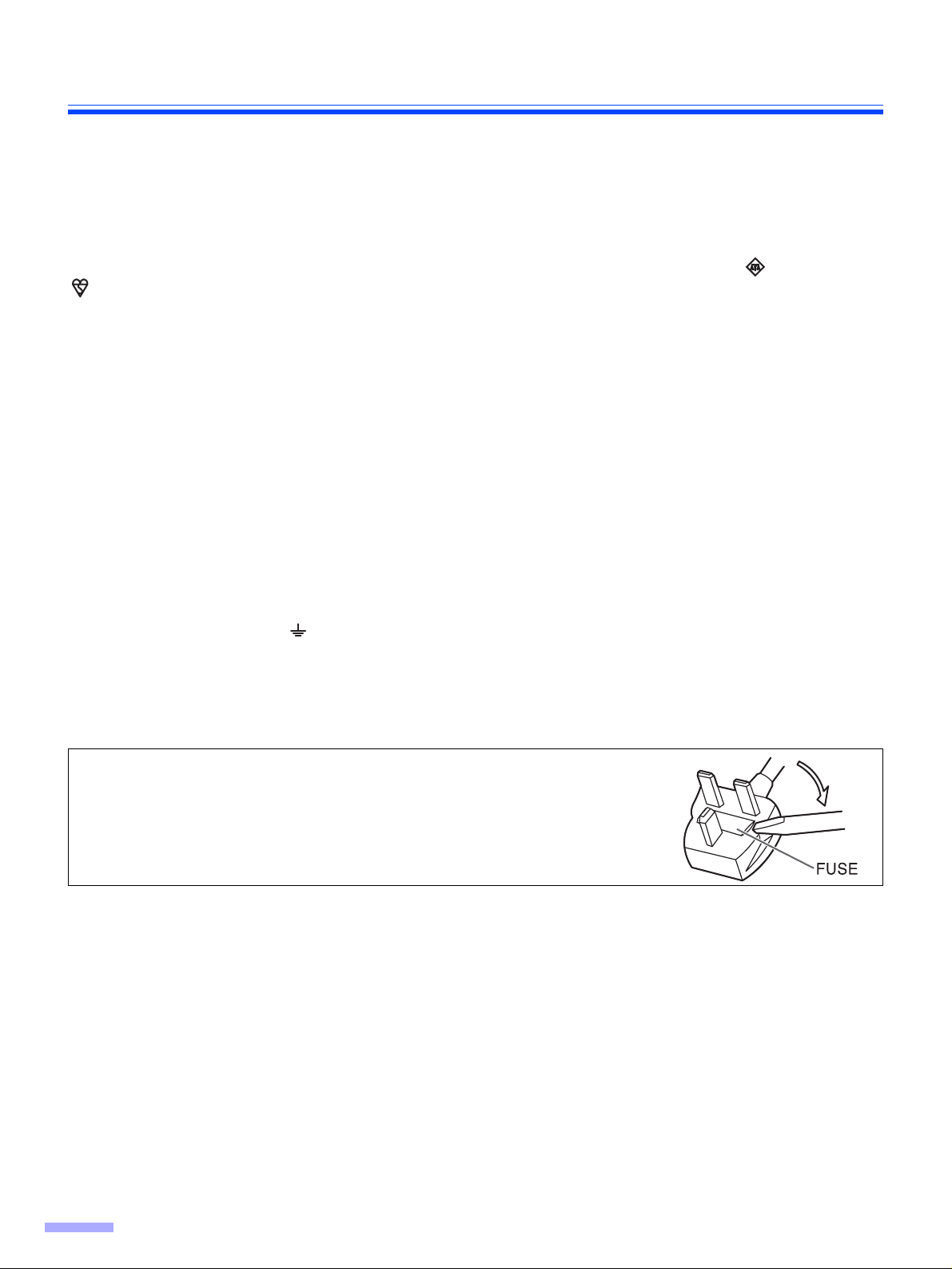
How to replace the fuse :
Open the fuse compartment with a screwdriver and replace
the fuse.
6
Page 7
Notice
English
The product should be used only with a power cord that is supplied by the manufacturer.
Français
Le produit ne devra être utilisé qu’avec le cordon d’alimentation fourni par le fabricant.
Deutsch
Dieses Gerät darf nur mit dem vom Hersteller gelieferten Netzkabel verwendet werden.
Español
Este producto deberá utilizarse solamente con el cable de alimentación suministrado por el
fabricante.
Svenska
7
Page 8

Notice
Roller cleaning paper precautions
Before using the roller cleaning paper, please read these instructions completely. Keep these instructions for future
reference.
English
WARNING
• Do not drink or inhale the roller cleaning paper fluid including isopropyl alcohol.
• The roller cleaning paper may be harmful to your skin, so please use protective gloves.
• Do not use the roller cleaning paper near a heater or open flame.
• Do not store the roller cleaning paper in direct sunlight or in a place over 40 oC (104 oF).
• Only use the roller cleaning paper to clean the rollers and scanning area.
• If you need more information about the roller cleaning paper, please refer to the Material Safety Data Sheet
(MSDS).
• Please ask your Panasonic sales company about obtaining the Material Safety Data Sheet.
KEEP AWAY FROM FIRE.
Français
Avertissement
• Ne pas absorber le liquide du papier de netto y age de rouleaux fourni ni en respirer les émanations car il contient
de l’alcool isopropylique.
• Le papier de nettoyage de rouleaux pouvant être néfaste pour les peaux sensibles, utiliser des gants de
protection.
• Ne pas utiliser le papier de nettoyage de rouleaux à proximité d’un feu ou d’une fl amme vive.
• Ne pas ranger le papier de nettoyage de rouleaux en plein soleil ni à une température dépassant 40 oC (104 oF).
• Utiliser le papier de nettoyage de rouleaux exclusivement pour le nettoyage des rouleaux et de la surface de
balayage.
• Pour tout renseignement complémentaire sur le papier de nettoyage de rouleaux, voir la feuille de données sur
la sécurité du matériel.
• Pour la feuille de données sur la sécurité du matériel, s’adresser au revendeur Panasonic.
NE PAS APPROCHER DU FEU.
Deutsch
WARNUNG
• Die Walzenreinigungspapier-Reinigungsflüssigkeit enthält Isopropylalkohol und darf auf keinen Fall getrunken
oder inhaliert werden.
• Bitte Schutzhandschuhe tragen, da das Walzenreinigungspapier bei empfindlicher Haut Reizungen verursachen
kann.
• Das Walzenreinigungspapier nicht in der Nähe von Heizgeräten oder offenen Flammen verwenden.
• Das Walzenreinigungspapier nicht in direkter Sonneneinstrahlung oder an Orten lagern, an denen Temperaturen von
mehr als 40 oC erreicht werden.
• Zum Reinigen der Walzen und des Scanbereichs ausschließlich das Walzenreinigungspapier verwenden.
• Weitere Informationen zum Walzenreinigungspapier sind dem Materialsicherheits-Datenblatt zu entnehmen.
• Das Materialsicherheits-Datenblatt ist auf Wunsch von Ihrem Panasonic-Fachhändler erhältlich.
VON FEUER FERNHALTEN!
8
Page 9
Notice
Español
ADVERTENCIA
• No beba el líquido del papel de limpieza de rodillos ni aspire las emanaciones del alcohol isopropílico que
contiene.
• El papel de limpieza de rodillos puede ser perjudicial para las pieles sensibles, por favor use guantes de
protección.
• No utilice el papel de limpieza de rodillos cerca de una calefacción o una llama.
• No guarde el papel de limpieza de rodillos expuesto a la luz solar directa ni en un lugar donde la temperatura
sea superior a 40°C.
• Utilice solamente papel de limpieza de rodillos para limpiar los rodillos y el área de escaneado.
• Si necesita más información acerca del papel de limpieza de rodillos, consulte la hoja de datos de seguridad del
material (MSDS).
• Pregunte a la compañía de ventas Panasonic cómo obtener la hoja de datos de seguridad del material.
MANTÉNGALO ALEJADO DEL FUEGO.
9
Page 10
Precautions
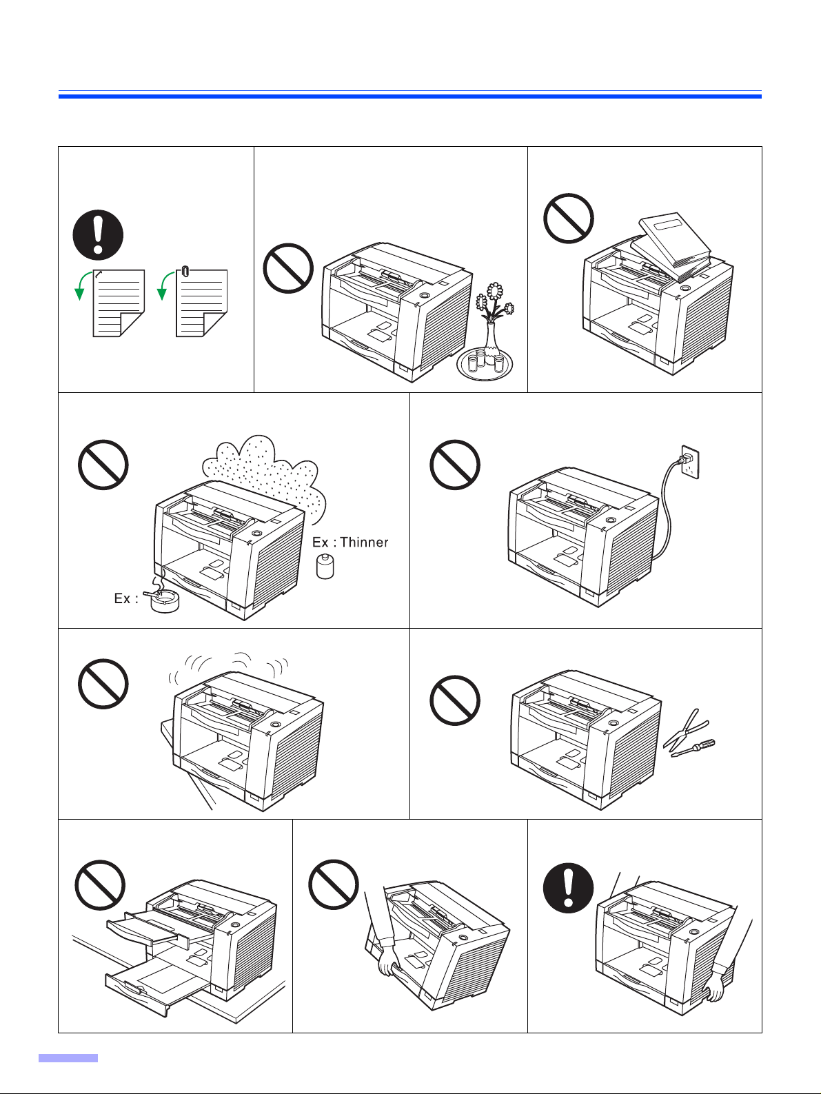
The following precautions are recommended to extend the life of the unit, and for your safety.
Prior to scanning, remove,
all staples and paper clips
from pages.
Do not place the unit in an area where there is a lot of
smoke, dust, chemical fumes or vibration.
Do not place any liquids near the unit.
—Accidental spillage of liquid into the unit
may cause severe damage. If this
occurs, turn the unit off, unplug the
power cord and call for service.
Do not place books, paper,
or other items on the unit.
Do not leave the power cord plugged into the AC outlet
if the unit is not used for an extended period.
Do not place the unit on an uneven or unstable surface. Do not disassemble the unit.
This will void your warranty.
Do not use the tray hanging out of a
table.
When carrying the unit, do not use
the trays as handles.
When carrying the unit, hold the
both side grips.
10
Page 11
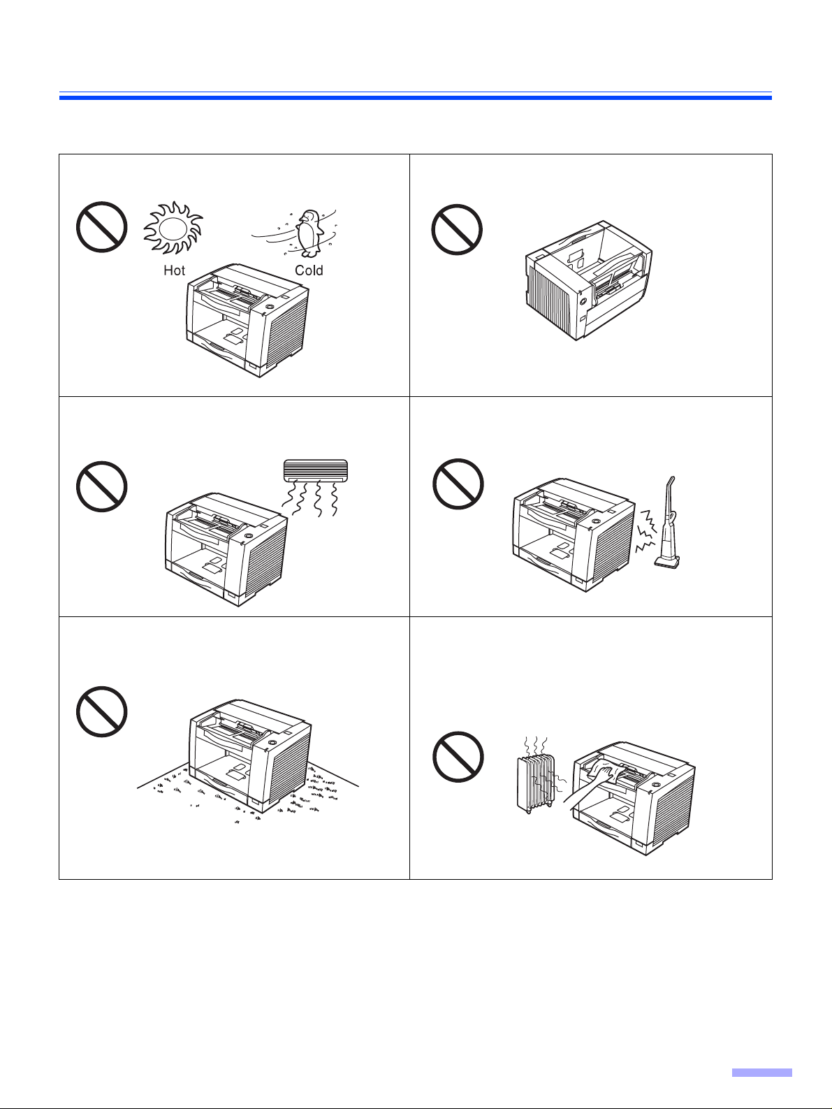
Operating Environment
Precautions
Do not place the unit in direct sunlight or in a cold
draft.
Do not place the unit near a heating appliance or an
air conditioning vent. Do not place the unit in a room
with extremely high or low humidity.
Do not use the unit in a vertical position.
Do not place the unit near other appliances which generate large electrical noise.
Do not place the unit on a carpet. (Static electricity
can cause the unit to malfunction.)
Do not drink or inhale the included roller cleaning paper
fluid.
The roller cleaning paper may be harmful to your skin,
so please use protective gloves.
Do not use the roller cleaning paper near a heater or
open flame. This may cause a fire.
≥Power Source
≥ Use a voltage level that does not vary more than d10% from the voltage level marked on the nameplate
(located on the back side of the scanner).
≥ Do not use an extension cord.
≥ This scanner should be connected to a grounded outlet.
≥ Do not use a line conditioner, transient suppressor or surge protector.
11
Page 12
Precautions
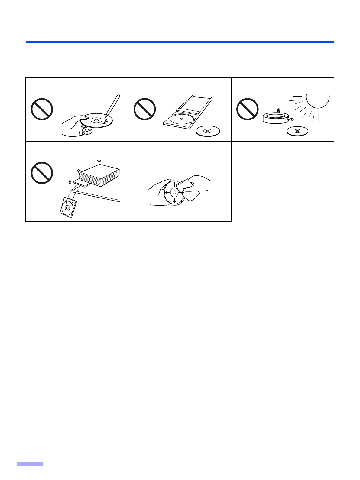
∫ CD-ROM
To prevent the CD-ROMs from accidental damages:
Do not touch or write on the surface
of the disc.
Do not place heavy objects on the
disc case or drop the case.
Do not leave the disc out of the
protective case.
To clean the disc, hold the disc by
its edges and wipe it from the
center to the edges with a dry, soft
cloth.
Do not leave the disc in direct
sunlight or near heat sources.
12
Page 13
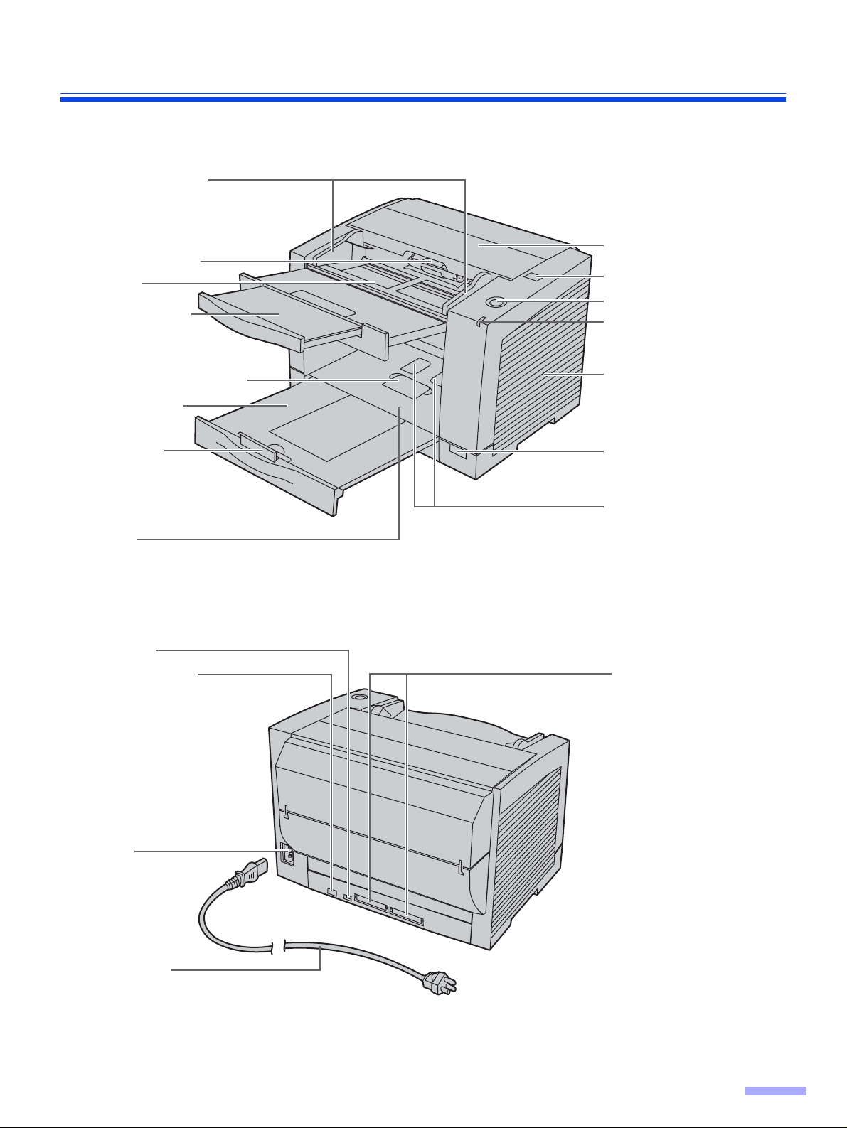
Component Identification
s
∫ KV-S2025C / KV-S2025CU / KV-S2026C / KV-S2026CU
Document guides
Paper feed roller
Feed tray
Feed extension
tray
ADF door
ADF door release
STOP/START button
LED
Business card stopper
Exit extension
tray
Exit stopper
Exit tray
DIP switch
USB connector
(Only for KV-S2026C,
KV-S2026CU)
Radiation vent
Power switch
Business card guide
SCSI connectors
AC inlet
Power cord
Po wer cord sho wn on the figure is
for 100-120 V.
13
Page 14

Component Identification
n
∫ KV-S2045C / KV-S2045CU / KV-S2046C / KV-S2046CU
Document guides
Imprinter door
Paper feed roller
Feed tray
Feed extension tray
Business card
stopper
Exit stopper
Exit extension
tray
Exit tray
DIP switch
USB connector
(Only for KV-S2046C,
KV-S2046CU)
ADF door
ADF door release
STOP/START butto
LED
Radiation vent
Power switch
Business card
guides
SCSI connectors
AC inlet
Power cord
Po wer cord sho wn on the figure is
for 100-120 V.
14
Imprinter door pull
Imprinter door
Page 15

∫ Power turn-on sequence
Turn on the power of the scanner.
1
≥ Pre ss the power switch.
(The LED will now light.)
Turn on the power of the host
2
computer after scanner’s LED ligh ts
.
green
≥ In case of the USB connection, the host
computer recognizes the scanner automatically when the scanner is po wered on
even after the host computer is powered
on.
Component Identification
LED
∫ About LED
LED indicates the status of the scanner as follows:
LED light Status
Green Ready to scan or scanning
Green (flashing) Sleep mode
Orange Ready to scan or scanning with warning *1
Orange (flashing) Initializing
Sleeping with warning *1
Red An error occurred *2
*1: The rollers need to be cleaned or replaced.
*1*2: Check the status of the scanner using the User utility.
The User utility is included in the CD-ROM.
15
Page 16

Component Identification
∫ About the SCSI setting
When connecting the scanner to a SCSI chain using a SCSI cabl e, perform the SCSI ID setting correctly.
The scanner is provided with a DIP switch for the SCSI ID No. setting and the terminator setting.
SCSI ID Setting
ID No.
#2 #1 #0
0OFF OFF OFF
1OFF OFF ON
2OFF ON OFF
3OFF ON ON
4ON OFF OFF
5ON OFF ON
6ONONOFFDefault setting
7ONONON
Switch
Remarks
SCSI Terminator Setting
Function Switch Description
Enable ON ≥ The last device in the SCSI chain
≥ Default setting
Disable OFF Not the last device in the SCSI chain
16
Page 17

Loading Documents
s
Documents that have been stapled
1
together or stacked together (as in a
file folder) will need to be separated.
1 Fan the stack of documents to sepa-
rate all the edges.
2 Hold both ends and bend the docu-
ments as shown in the illustration.
3 To flatten the documents, hold firmly
and pull them apart as shown in the
illustration.
Repeat these steps as necessary.
Carefully align the documents.
2
Prior to scanning, remove, all staples and paper clip
from pages.
1
2
3
Adjust the document guides slightly
3
larger than the actual size of the documents.
Document guides
17
Page 18

Loading Documents
When scanning paper longer than the
4
feed tray, pull out the feed extension
tray from the feed tray and the exit
extension tray as shown in the figure
on the right.
≥ The exit extension tray of KV-S2045C,
KV-S2045CU, KV-S2046C and KV-S2046CU
is fixed. Adjust the position of the exit
stopper.
≥ When using small sized documents like
business cards, raise the business card
guides and the business card stopper.
Caution:
Do not use the business card guides and the
business card stopper for larger documents
than their acceptable size. It will cause paper
jams.
Feed extension tray
Exit stopper
Exit extension tray
A
Place the documents on the feed tray
5
with the side to be scanned facing up.
≥ Be sure to place the documents on the
feed tray as shown in the figure on the
right.
≥ The amount of documents should not
exceed the limit mark on the document
guide. This may cause a paper jam or
skew.
Business card guides Business card stopper
Paper feed roller
Feed tray
18
Page 19

Loading Documents
Adjust the document guides to the size
6
of the documents.
Set documents under the paper feed
7
roller.
1 Lift the paper feed roller as shown in
the figure.
2 Push documents in the direction of
the arrow until they stop under the
paper feed roller.
Document guides
Paper feed roller
1
2
Caution:
≥ Acceptable documents are as follows.
Paper size: 50.8 k 70 mm (2.0 k 2.8 in.)
Paper thickness:
Single paper feed: 0.05
Continuous paper feed: 0.06 to 0.15 mm (2.36 to 5.9 mils)
Paper weight:
Single paper feed: 40 to 127 g/m
Continuous paper feed: 50 to 127 g/m
If you scan other types of documents, paper jamming or multiple-sheet feeding may occur.
≥ Scanning paper such as carbons or carbonless paper may cause skewing, paper jamming or multiple-sheet
feeding because it makes the rollers dirty and the chemicals may cause the rollers to swell up.
≥ The amount of documents should not exceed the limit mark on the document guide. This may cause a paper
jam or skew.
≥ Be sure to remove the document from the exit tray after it is scanned.
≥ When you scan the irregular or fragile documents , it is recommended to make a copy and use the copy to scan.
≥ When scanning a curled or folded document, load the document after flattening it.
to 0.15 mm (2.0 to 5.9 mils)
to 216 k 356 mm (8.5 k 14 in.)
2
(10.7 to 33.9 lbs.)
2
(13.3 to 33.9 lbs.)
Types of documents to avoid:
≥ OHP sheets, other plastic films, cloths, or metallic sheets.
≥ Paper with irregularities such as tabs, staples, paste, etc.
≥ Documents with wet ink
≥ Thick or irregular documents such as envelopes, documents that are glued together, etc.
≥ Copying paper such as carbon paper
≥ Damaged or wrinkled documents
≥ Irregularly shaped documents
≥ Photographs
19
Page 20

Clearing Paper Jams
Torn documents, thin documents or documents that are creased on the top edge may cause paper jams. If a paper
jam occurs, remove the jammed sheet according to the following procedure.
∫ Removing paper jams from the feed part
Push the ADF door release to open the
1
ADF door.
Remove the jammed document.
2
≥ If the jammed document remains at the
feed tray side, pull it up.
≥ If the jammed document appears at the
exit tray side, remove it from the exit side.
20
Page 21

Make sure that the sensor rollers are
3
installed properly, before closing the
ADF door.
≥ If the sensor rollers are removed, re-
attach them. (Refer to page 32.)
Clearing Paper Jams
Sensor roller (front)
Close the ADF door.
4
≥ When you close the ADF door, close it
securely until the door is locked.
Sensor roller (back)
21
Page 22

Cleaning the Unit
∫ Outside of the scanner
Clean the unit at least once a month.
Turn the power off.
1
Clean the cover with a soft cloth.
2
Remove dirt and dust from the radia-
3
tion vent with a brush.
∫ Inside the scanner
≥ Clean the unit at least once a week or when 20,000 sheets have been scanned, whichever comes first.
≥ Clean the rollers and sensors if paper jamming or multiple-sheet feeding occurs frequently. (Refer to pages 23-
25.)
≥ Clean the CIS glasses and sensor rollers when lines appear on the scanned images . (Refer to pages 25-26.)
≥ If the documents you scan are dirty, then the scanner c omponents will also become dirty. To maintain proper
scanning, clean the scanner components frequently.
Radiation vent
22
Page 23

∫ Cleaning the rollers and sensors
Roller cleaning paper:
Open the bag on the dotted line and take out
the roller cleaning paper.
Cleaning the Unit
≥ If the roller cleaning pa per ba g is le ft opened for
a long period of time before using it, the alc ohol
will evaporate. Please use the roller cleaning
paper immediately after opening the bag.
The roller cleaning paper (Model No . KV-SS03)
is available from the dealer where you purchased your scanner.
For supplies and accessories: Call
1-800-346-4768 (U.S .A. only) or your dealer.
Turn the power off.
1
Dotted line
Push the ADF door release to open the
2
ADF door.
23
Page 24

Cleaning the Unit
Use the roller cleaning paper (KV-SS03)
3
to remove the dirt from the surfaces of
the retard roller, paper feed roller,
separation roller, 6 drive rollers, and 6
free rollers.
paper sensors (Paper detector, Waiting
sensor, Starting position sensor) and
reflector sheets with a cotton swab.
≥ When wiping off the dirt on the roller sur-
faces, hold the rollers to prevent them
from rotating, and wipe the rollers all the
way around them proceeding from one
end to the other in the directions of the
arrows shown in the figure on the right.
Also, remove dust on the
Paper detector
Retard roller
Reflector sheets
Clean the reflector sheet for the ending
4
sensor.
≥ Remove dust on the reflector sheet of the
ending sensor with a cotton swab.
≥ Th e reflector sheet is behind the shaft.
Drive rollers
Waiting sensor
Free rollers
Drive rollers
Paper feed roller
Separation roller
Free rollers
Starting position sensor
24
Reflector sheet
for ending sensor
Cotton swab
Page 25

Make sure that the sensor rollers are
5
installed properly, before closing the
ADF door.
Close the ADF door.
6
Clear the roller cleaning counter with
7
User Utility.
≥ After cleaning the above rollers, click
[Clear Counter] button for [After Clean
Roller] with User Utility.
∫ Cleaning the CIS glasses and sensor rollers
Turn the power off.
1
Cleaning the Unit
Push the ADF door release to open the
2
ADF door.
25
Page 26

Cleaning the Unit
Clean the CIS glasses and sensor roll-
3
ers using the roller cleaning paper.
≥ If the sensor rollers are removed while
cleaning, re-attach them after cleaning.
Sensor roller (front)
CIS glass (front)
Sensor roller (back)
26
Sensor roller (front)
CIS glass (back)
Close the ADF door.
4
≥ When you close the ADF door, close it
securely until the door is locked.
Page 27

Replacing Consumables
∫ Replacing the paper feed roller module
Turn the power off.
1
Push the ADF door release to open the
2
ADF door.
Push the two green levers down at
3
both ends of the paper feed roller module to unlock the paper feed rollers.
≥ When moving the green levers, do not
apply pressure in any other direction
other than in the direction shown by th e
arrows. Otherwise the levers may break.
27
Page 28

Replacing Consumables
Remove the paper feed roller module
4
straightly, holding up the paper feed
case along the groove of the f eed co v er
to pull out the claw out of the case.
Claw
Groove
Paper feed case
Install the new paper feed roller mod-
5
ule with its gear on the right.
1 Hang both ends of the paper feed
roller module.
2 While slightly lifting the paper feed
roller module, pass the claw along
the groove of the feed cover.
3 Attach the bearings at both ends of
the paper feed roller module into the
guide grooves of the chassis in the
scanner.
.
Chassis
Bearings
28
Green levers
Page 29

Push up the green levers at both ends
6
in the direction of the arrows until they
click into place.
≥ After installing the paper feed roller
module, confirm that the feed rollers
can be moved lightly in vertical direction.
Replacing Consumables
Close the ADF door.
7
≥ When you close the ADF door, close it
securely until the door is locked.
29
Page 30

Replacing Consumables
∫ Replacing the retard roller module
Turn the power off.
1
Push the ADF door release to open the
2
ADF door.
Remove the retard roller cover.
3
Remove the retard roller module in the
4
direction of the arrow.
Retard roller cover
30
Retard roller module
Page 31

Replacing Consumables
Install the new retard roller module by
5
matching the groove of its shaft with
the groove of the metal holder.
Make sure that both ends of the shaft
reach the springs of the holder.
Close the retard roller cover.
6
Wider groove
Metal holder
Close the ADF door.
7
≥ When you close the ADF door, close it
securely until the door is locked.
Clear the roller replacing counter with
8
User Utility.
≥ Click [Clear Counter] button for [After
Replace Roller] with User Utility.
31
Page 32

How to re-attach the sensor rollers
If the sensor rollers are removed, re-attach them.
∫ Re-attach the sensor roller for back scanning to the ADF door
Attach the shorter sensor roller to the ADF
door by placing the non-gear side to the ADF
door release.
≥ Match the groove to the guide.
≥ Push the roller, and confirm the sensor is locked
by the springs on both sides.
Springs
∫ Re-attach the sensor roller for front scanning
Attach the longer roller to the unit by placing
the non-gear side to the ADF door release.
≥ Match the groove to the guide.
≥ Attach the side of the ADF door release first, and
attach the other side.
Confirm both rollers move slightly.
≥ Press down on the sensor rollers and rotate them.
32
Page 33

Repacking Instructions
∫ KV-S2025C / KV-S2025CU / KV-S2026C / KV-S2026CU
It is highly recommended that you keep the original carton and ALL packing materials. If you need to transport or
ship your scanner, please follow these instructions.
Please Note:
≥ Please use the original carton and all of the original packing materials.
≥ Improper repacking of the scanner may result in a service charge to repair the unit.
≥ The scanner should be handled in the correct (horizontal) position.
Materials Required:
≥ Original Scanner Carton & Packing Materials
≥ Shipping Tape and Scissors
Turn the power switch off and disconnect your scanner from the electr ical outlet and the
1
interface cable.
Return the feed extension tray, exit stopper and exit extension tray to their original posi-
2
tions.
Pac k the scanner.
3
Power cord
≥ Be sure to use a
power cord whose
shape matches the
shape of the electric
outlet.
CD-ROM (2 pieces)
33
Page 34

Repacking Instructions
∫ KV-S2045C / KV-S2045CU / KV-S2046C / KV-S2046CU
It is highly recommended that you keep the original carton and ALL packing materials. If you need to transport or
ship your scanner, please follow these instructions.
Please Note:
≥ Please use the original carton and all of the original packing materials.
≥ Improper repacking of the scanner may result in a service charge to repair the unit.
≥ The scanner should be handled in the correct (horizontal) position.
Materials Required:
≥ Original Scanner Carton & Packing Materials
≥ Shipping Tape and Scissors
Turn the power switch off and disconnect your scanner from the electr ical outlet and the
1
interface cable.
Remove the feed extension tray and exit extension tray.
2
Pac k the scanner.
3
Powe r co rd
≥ Be sure to use a
power cord whose
shape matches the
shape of the electric
outlet.
Tray
CD-ROM
Note: How to remove the feed extension tray
1 Pull up the tray.
2 With pressing down the center of the tray,
3 pull out the tray.
Feed extension tray
2
2
3
1
34
Page 35

Specifications
Model No. KV-S2025C
Items
Scanner Scanning face Duplex
Scanning method CIS (Contact-type color image sensor) Front & Back sides
Scanning
speed
*1
Letter size
portrait
Scanning
speed
*1
A4 size
portrait
Resolution 100-600 dpi (10 dpi step)
Tonal gradation Binary mode, Gray scale mode (4/8 bit), Dither mode (16/256
Binary
200 dpi
Color
150 dpi
Binary
200 dpi
Color
150 dpi
KV-S2026C
Background: Black sensor roller
SimplexApprox. 23 pages/min.
Duplex Approx. 42 images/min.
SimplexApprox. 10 pages/min.
Duplex Approx. 18 images/min.
SimplexApprox. 22 pages/min.
Duplex Approx. 40 images/min.
SimplexApprox. 9 pages/min.
Duplex Approx. 16 images/min.
Optical: 600 dpi (Main and Sub scanning derections)
step), Error diffusion
Note: Dither and Error diffusion are executed by driver
KV-S2025CU
KV-S2026CU
software or RTIV.
KV-S2045C
KV-S2046C
SimplexApprox. 43 pages/min.
Duplex Approx. 76 images/min.
SimplexApprox. 19 pages/min.
Duplex Approx. 34 images/min.
SimplexApprox. 41 pages/min.
Duplex Approx. 72 images/min.
SimplexApprox. 18 pages/min.
Duplex Approx. 32 images/min.
KV-S2045CU
KV-S2046CU
Image control Image emphasis (5 step), Dynamic threshold, Automatic
separation, Noise reduction, Deskew, Cropping, Mirror image,
Monochrome reversing, Gamma correction
Note: These all functions are executed by driver software or
RTIV.
Other function Patch code detection (Kodak patch 2, 3, T)
Note: 1 portion both side each executed only by ISIS driver.
Paper Size 50.8k70 mm (2.0k2.8 in.) to 216k356 mm (8.5k14 in.)
Note: The setting of the paper length is possible to 25 inches in
TWAIN, ISIS and RTIV .
In case of a paper beyond legal size, 1 by 1 paper
scanning in the resolution under 300 dpi is recommended.
Thickness Single paper feeding: 0.05 to 0.15 mm (2.0 to 5.9 mils)
Continuous paper feeding: 0.06 to 0.15 mm (2.36 to 5.9 mils)
Note: 1 mil = 1/1000 in.
Weight Single paper feeding: 40 to 127 g/m
Continuous paper feeding: 50 to 127 g/m
Note: 1 lbs = 3.75 g/m
Interface (Transfer rate) SCSI III (20 M B /se c)
USB 2.0 (Only for KV-S2026C, KV-S2026CU, KV-S2046C,
KV-S2046CU)
Feed tray capacity 120 sheets [64 g/m
2
2
(17 lbs.)], 100 sheets [75 g/m2 (20 lbs.)]
2
(10.7 to 33.9 lbs.)
2
(13.3 to 33.9 lbs.)
35
Page 36

Specifications
Model No. KV-S2025C
Items
Unit External dimensions
(WidthkDepthkHeight)
Weight 8.4 kg (18.5 lbs.)
Power requirement AC100
Power
consumption
Environment Operating temperature
and humidity
Maximum
(Scanning)
Minimum
(Standby)
Sleep mode 0.1 A (5 W)
KV-S2025CU
KV-S2026C
343k487k269 mm
(13.5k19.2k10.6 in.)
Note: When tray is pulled
[KV-S2025C, KV-S2025CU]
8.5 kg (18.7 lbs.)
[KV-S2026C, KV-S2026CU]
–
120 V
50/60 Hz
1 A 0.5 A 1 A 0.5 A
0.3 A 0.2 A 0.35 A 0.2 A
[KV-S2025C]
0.15 A (6 W)
[KV-S2026C]
Temperature: 15 °C to 30 °C (59 °F to 86 °F)
Humidity: 30% to 80% RH
KV-S2026CU
AC220 – 240 V
50/60 Hz
0.1 A (7 W)
[KV-S2025CU]
0.1 A (8 W)
[KV-S2026CU]
KV-S2045C
KV-S2046C
343k487k239 mm
(13.5k19.2k9.4 in.)
Note: When tray is installed
9.1 kg (20.1 lbs.)
AC100 – 120 V
50/60 Hz
0.15 A (6 W) 0.1 A (7 W)
KV-S2045CU
KV-S2046CU
AC220 – 240 V
50/60 Hz
[KV-S2045CU]
0.1 A (8 W)
[KV-S2046CU]
Storage temperature
and humidity
Accessories Po wer cord, Roller cleaning paper, CD-ROM(s) (Ma intenance,
Option White roller kit (KV-SS023)
Temperature: 0 °C to 35 °C (32 °F to 95 °F)
Humidity: 10% to 80% RH
Safety and Installation manual, Operating instructions,
RTIV Capture software, ISIS driver, TWAIN driver,
PIE reference manual, RTIV reference manual, User utility),
Printed documents (Maintenance, Safety and Installation manual)
White roller kit (KV-SS023)
Roller exchange kit (KV-SS022)
Roller cleaning paper (KV-SS03)
Roller exchange kit (KV-SS022)
Roller cleaning paper (KV-SS03)
Pre-imprinter (KV-SS020)
Ink cartridge (KV-SS021)
Note
*1: The scanning speed depends on the test environment.
The scanning speed differs depending on the host computer operating environment or application.
36
Page 37

Troubleshooting
If a problem occurs while the unit is being used, check the following items and check the scanner status by User Utility.
If the unit still malfunctions, turn it OFF, unplug the pow er cord and call for service.
Symptom Possible Cause Remedy
The LED does not light when the
power switch is turned ON.
The computer does not recognize
the scanner.
SCSI
connection
The power cord is not plugged in. Insert the power plug firmly.
Problem with power supply.
The scanner is not connected to the
computer correctly.
The scanner is not registered
correctly.
The computer cannot recognize the
SCSI card.
The same ID number is used for the
scanner and the other device.
The terminator is not set correctly.
Disconnect the scanner from the
electric outlet and call for service.
Connect the cables correctly.
Uninstall the scanner from PC.
Register the scanner hardware
again. (Refer to the Installation
Manual on pages 22 and 23.)
Check your computer whether the
SCSI card is installed correctly
using the device manager’s property.
Use the different SCSI ID numbers
for each dev ices.
If the scanner is the last device in
the SCSI chain, set the DIP switch
of SCSI terminator to Enable.
If the scanner is not the last device
in the SCSI chain, set the DIP
switch of SCSI terminator to Disable.
USB
connection
Scan speed is slow at USB connection.
The ADF does not open when the
ADF door release is pushed.
The scanner was turned on after
the computer was turned on.
The USB interface of the computer
is not installed correctly.
The scanner is connected via USB
hub.
The cable without High-Seed logo
is used.
The scanner is connected with USB
1.1.
The ADF door is not closed
properly.
Turn the computer OFF. Turn the
scanner ON, and then turn the computer ON again.
Check the computer whether the
USB interface of your computer is
correctly using the device manager’s property.
Do not connect via USB hub.
Use the cable with High-Speed
logo.
Connect with USB 2.0.
Push the ADF door release again
after you close the ADF door until it
is locked.
37
Page 38

Troubleshooting
Symptom Possible Cause Remedy
The document has been loaded on
the feed tray. But the scanner does
not start scanning.
Double feeding or skewing problems occur frequently or the scanner stops loading while scanning.
The scanned document is blank.
The document is not loaded
properly.
The sensor cannot detect the document as the edge of the document
is curled.
The rollers are dirty.
The rollers have reached their life
expectancy.
The document is curled or folded.
The irregular type document is to
be scanned.
The document has a length of less
than 70 mm (2.75z).
The document to be scanned was
loaded face down (upside down).
Load the document correctly.
(See page 17.)
Flatten the document and load it
again.
Clean all of the rollers.
(See page 23.)
Replace the paper feed roller module and the retard roller module.
(See page 27 and page 30.)
Flatten the document and load it
again after reducing the pages.
Make a copy of the document on
specified paper (see page 35) and
scan the copy.
Make a copy of the document on
paper of the specified size and scan
the copy.
Load the document correctly.
(See page 17.)
Vertical lines appear on the
scanned document.
The scanning density is uneven.
The color of the scanned document
is extremely different from the original document.
Dark spots or noise appear on the
scanned documents.
Scanned image has moire fringes
such as stripe or wavy pattern
noise.
The CIS glasses are dirt y.
The sensor rollers are dirty.
The CIS glasses or the sensor
rollers are dirty.
The setting of the monitor is wrong. Adjust the monitor setting.
The CIS glasses or the sensor
rollers are dirty.
It is caused by printing pattern of
the document and the congeniality
of the scanning resolution.
Clean the CIS glasses.
(See page 25.)
Clean the sensor rollers.
(See page 25.)
Clean the CIS glasses and the
sensor rollers.
(See page 25.)
Clean the CIS glasses and the
sensor rollers.
(See page 25.)
Please change the resolution and
try to scan.
38
Page 39

Index
Page Page
A
AC inlet. . . . . . . . . . . . . . . . . . . . . . . . 13, 14
Acceptable documents . . . . . . . . . . . . . . . 19
Accessories . . . . . . . . . . . . . . . . . . . . . . . 36
ADF door . . . . . . . . . . . . . . . . . . . . . . 13, 14
ADF door release . . . . . . . . . . . . . . . . 13, 14
B
Business card guides . . . . . . . . . . 13, 14, 18
Business card stopper . . . . . . . . . 13, 14, 18
C
CD-ROM. . . . . . . . . . . . . . . . . . . . . . . . . . 12
CIS glasses. . . . . . . . . . . . . . . . . . . . . . . . 26
Cleaning the CIS glasses . . . . . . . . . . . . . 25
Cleaning the rollers. . . . . . . . . . . . . . . . . . 23
Cleaning the sensor rollers. . . . . . . . . . . . 25
Cleaning the sensors . . . . . . . . . . . . . . . . 23
Component identification . . . . . . . . . . . . . 13
G
Green levers . . . . . . . . . . . . . . . . . . . . . . 27
I
Image control. . . . . . . . . . . . . . . . . . . . . . 35
Imprinter door. . . . . . . . . . . . . . . . . . . . . . 14
Imprinter door pull . . . . . . . . . . . . . . . . . . 14
Interface. . . . . . . . . . . . . . . . . . . . . . . . . . 35
L
LED . . . . . . . . . . . . . . . . . . . . . . . 13, 14, 15
Limit mark . . . . . . . . . . . . . . . . . . . . . . . . 18
Loading documents . . . . . . . . . . . . . . . . . 17
O
Operating temperature and humidity . . . . 36
Option . . . . . . . . . . . . . . . . . . . . . . . . . . . 36
D
DIP switch. . . . . . . . . . . . . . . . . . . 13, 14, 16
Document guides . . . . . . . . . . . . . 13, 14, 17
Documents to avoid . . . . . . . . . . . . . . . . . 19
Drive rollers. . . . . . . . . . . . . . . . . . . . . . . . 24
E
Exit extension tray . . . . . . . . . . . . 13, 14, 18
Exit stopper. . . . . . . . . . . . . . . . . . . . . 13, 14
Exit tray. . . . . . . . . . . . . . . . . . . . . . . . . . . 13
External dimensions . . . . . . . . . . . . . . . . . 36
F
Feed extension tray . . . . . . . . . . . 13, 14, 18
Feed tray. . . . . . . . . . . . . . . . . . . . 13, 14, 18
Feed tray capacity . . . . . . . . . . . . . . . . . . 35
Free rollers . . . . . . . . . . . . . . . . . . . . . . . . 24
P
Paper . . . . . . . . . . . . . . . . . . . . . . . . . . . . 35
Paper detector . . . . . . . . . . . . . . . . . . . . . 24
Paper feed roller . . . . . . . . . . . . . 13, 14, 24
Paper feed roller module . . . . . . . . . . . . . 27
Paper jams. . . . . . . . . . . . . . . . . . . . . . . . 20
Power consumption . . . . . . . . . . . . . . . . . 36
Power cord. . . . . . . . . . . . . . . . . . . . . 13, 14
Power requirement. . . . . . . . . . . . . . . . . . 36
Power switch . . . . . . . . . . . . . . . . . . . 13, 14
Precautions . . . . . . . . . . . . . . . . . . . . . . . 10
R
Radiation vent . . . . . . . . . . . . . . . 13, 14, 22
Reflector sheets. . . . . . . . . . . . . . . . . . . . 24
Repacking . . . . . . . . . . . . . . . . . . . . . . . . 33
Replacing consumables. . . . . . . . . . . . . . 27
Replacing the retard roller module. . . . . . 30
Resolution . . . . . . . . . . . . . . . . . . . . . . . . 35
Retard roller. . . . . . . . . . . . . . . . . . . . . . . 24
39
Page 40

Page
Retard roller cover . . . . . . . . . . . . . . . . . . 30
Retard roller module. . . . . . . . . . . . . . . . . 30
Roller cleaning paper . . . . . . . . . . . 8, 23, 26
S
Scanning face. . . . . . . . . . . . . . . . . . . . . . 35
Scanning method . . . . . . . . . . . . . . . . . . . 35
Scanning speed . . . . . . . . . . . . . . . . . . . . 35
SCSI connectors. . . . . . . . . . . . . . . . . 13, 14
SCSI setting . . . . . . . . . . . . . . . . . . . . . . . 16
SCSI terminator . . . . . . . . . . . . . . . . . . . . 16
Sensor rollers . . . . . . . . . . . . . . . . 21, 26, 32
Separation roller . . . . . . . . . . . . . . . . . . . . 24
Specifications . . . . . . . . . . . . . . . . . . . . . . 35
Starting position sensor . . . . . . . . . . . . . . 24
STOP/START button . . . . . . . . . . . . . 13, 14
Storage temperature and humidity . . . . . . 36
System requirements . . . . . . . . . . . . . . . . . 2
T
Tonal gradation. . . . . . . . . . . . . . . . . . . . . 35
Troubleshooting . . . . . . . . . . . . . . . . . . . . 37
U
User Utility . . . . . . . . . . . . . . . . . . . . . 25, 31
W
Waiting sensor . . . . . . . . . . . . . . . . . . . . . 24
Weight. . . . . . . . . . . . . . . . . . . . . . . . . . . . 36
40
Page 41

41
Page 42

Panasonic Digital Document Compan y
A Unit of Matsushita Electric Corporation of America
Two Panasonic Way, Secaucus, New Jersey 07094
Panasonic Canada Inc.
5770 Ambler Drive, Mississauga , Ontario, L4W 2T3
Matsushita Electric Industrial Co., Ltd.
Web Site: http://www.panasonic.co.jp/global/
© 2002-2003 Panasonic Communications Co., Ltd.
E-0303M0
 Loading...