

Panasonic HC-X1500, HC-X2000 Users guide
Operating Instructions
E
4K Video Camera
Model No.
HC- X1500
HC- X2000
Please read these instructions carefully before using this product, and save this manual for future use.
DVQP2152YA
F0220SQ1100
Information for Your Safety
Information for Your Safety
For the AC mains plug of three pins
∫ Caution for AC mains lead
For your safety, please read the following text carefully.
This appliance is supplied with a moulded three pin mains plug for
your safety and convenience. A 5-ampere fuse is fitted in this plug.
Should the fuse need to be replaced please ensure that the
replacement fuse has a rating of 5-ampere and that it is approved by
ASTA or BSI to BS1362.
Check for the ASTA mark Ï or the BSI mark Ì on the body of the
fuse.
If the plug contains a removable fuse cover you must ensure that it is
refitted when the fuse is replaced.
If you lose the fuse cover the plug must not be used until a
replacement cover is obtained.
A replacement fuse cover can be purchased from your local dealer.
Before use
Remove the connector cover.
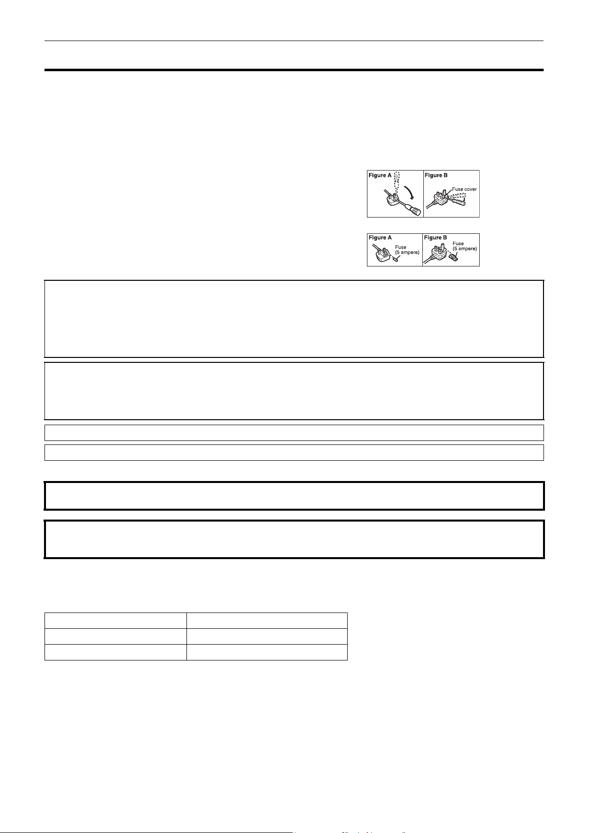
How to replace the fuse
The location of the fuse differ according to the type of AC mains plug
(figures A and B).
Confirm the AC mains plug fitted and follow the instructions below.
Illustrations may differ from actual AC mains plug.
1. Open the fuse cover with a screwdriver.
2. Replace the fuse and close or attach the fuse cover.
WARNING:
To reduce the risk of fire, electric shock or product damage,
≥ Do not expose this unit to rain, moisture, dripping or splashing.
≥ Do not place objects filled with liquids, such as vases, on this unit.
≥ Use the recommended accessories.
≥ Do not remove covers.
≥ Do not repair this unit by yourself. Refer servicing to qualified service personnel.
CAUTION!
To reduce the risk of fire, electric shock or product damage,
≥ Do not install or place this unit in a bookcase, built-in cabinet or in another confined space. Ensure this unit is well ventilated.
≥ Do not obstruct this unit’s ventilation openings with newspapers, tablecloths, curtains, and similar items.
≥ Do not place sources of naked flames, such as lighted candles, on this unit.
The mains plug is the disconnecting device. Install this unit so that the mains plug can be unplugged from the socket outlet immediately.
This unit is intended for use in moderate climates.
∫ Concerning the battery
Warning
Risk of fire, explosion and burns. Do not disassemble, heat above 60 oC or incinerate.
CAUTION
≥ Danger of explosion if battery is incorrectly replaced. Replace only with the type recommended by the manufacturer.
≥ When disposing of the batteries, please contact your local authorities or dealer and ask for the correct method of disposal.
∫ EMC Electric and magnetic compatibility
This symbol (CE) is located on the rating plate.
∫ Product identification marking
Product Location
4K Video Camera Bottom
AC adaptor Bottom
- 2 -
Information for Your Safety
∫ Disposal of Old Equipment and Batteries
Only for European Union and countries with recycling systems
These symbols on the products, packaging, and/or accompanying documents mean that used electrical and electronic products
and batteries must not be mixed with general household waste.
For proper treatment, recovery and recycling of old products and used batteries, please take them to applicable collection points
in accordance with your national legislation.
By disposing of them correctly, you will help to save valuable resources and prevent any potential negative effects on human
health and the environment.
For more information about collection and recycling, please contact your local authority.
Penalties may be applicable for incorrect disposal of this waste, in accordance with national legislation.
Note for the battery symbol (bottom symbol):
This symbol might be used in combination with a chemical symbol. In this case it complies with the requirement set by the
Directive for the chemical involved.
Declaration of Conformity (DoC)
Hereby, “Panasonic Corporation” declares that this product is in compliance with the essential requirements and other relevant provisions of
Directive 2014/53/EU.
Customers can download a copy of the original DoC to our RE products from our DoC server:
http://www.ptc.panasonic.eu
Contact to Authorized Representative:
Panasonic Marketing Europe GmbH, Panasonic Testing Centre, Winsbergring 15, 22525
Hamburg, Germany
Maximum power and operating frequency bands of transmitter
Type of wireless Frequency band (central frequency) Maximum power (dBm e.i.r.p.)
WLAN 2412-2462 MHz 13 dBm
For Turkey
AEEE Yönetmeliğine Uygundur.
AEEE Complies with Directive of Turkey.
Note regarding the Power Management function specified under COMMISSION REGULATION (EC) No 1275/2008 implementing Directive
2009/125/EC of the European Parliament and of the Council.
This device is designed and manufactured for use at a broadcasting station and/or in a similar environment.
This device is not equipped with a Power Management function or the Power Management function is set to OFF as it will prevent the device
from fulfilling its intended purpose for the reasons below.
1. If the device is a Studio Camera, a Weather Camera, a Mixer or other processor:
A Power Management function may cause the device to suddenly stop during recording or while On Air.
2. If the device is a Studio Monitor:
A Power Management function may cause video for the confirmation of whether a signal is normal, or whether the signal has been lost, to
be un-viewable.
3. If the device is a Camera Recorder:
A professional camera recorder must be able to start quickly at any time, but a Power Management function will cause an increase in the
time taken to resume from Stand-by mode.
AC Adaptor
Disconnect the AC mains plug from the AC mains socket when not in use.
For more information about the energy efficiency of the product, please visit our website, www.panasonic.com
the search box.
, and enter the model number in
- 3 -

Information for Your Safety
Í
∫ Cautions for use
Keep this unit as far away as possible from electromagnetic equipment (such as microwave ovens, TVs, video games etc.).
≥ If you use this unit on top of or near a TV, the pictures and/or sound on this unit may be disrupted by electromagnetic wave radiation.
≥ Do not use this unit near cell phones because doing so may result in noise adversely affecting the pictures and/or sound.
≥ Recorded data may be damaged, or pictures may be distorted, by strong magnetic fields created by speakers or large motors.
≥ Electromagnetic wave radiation generated by microprocessors may adversely affect this unit, disturbing the pictures and/or sound.
≥ If this unit is adversely affected by electromagnetic equipment and stops functioning properly, turn this unit off and remove the battery or
disconnect AC adaptor. Then reinsert the battery or reconnect AC adaptor and turn this unit on.
Do not use this unit near radio transmitters or high-voltage lines.
If you record near radio transmitters or high-voltage lines, the recorded pictures and/or sound may be adversely affected.
Do not lift up this unit by the handle with the tripod still attached
≥ When the tripod is attached, its weight will also affect the unit’s handle, possibly causing the handle to break and hurting the user.
≥ To carry the unit while the tripod is attached, take hold of the tripod.
Do not swing the unit around, shake it by, or allow it hang from the handle
≥ Do not jar, swing, or shake the unit by its handle. Any strong jolt to the handle may damage the unit or result in personal injury.
Do not allow the cord to drag on the ground or pull a connected cord along the passage
≥ The cord will be damaged, causing fire or electrical shock, when the cord gets caught by the feet, excite will also cause personal injury.
When this unit is turned on, do not use it in direct contact with the skin for a long period of time.
≥ When using this unit for a long period of time, use a support such as a tripod. Low temperature burns may result if any high temperature part
of this unit or hot air from the ventilation openings on the front side of the hand strap of this unit is in direct contact with the skin for a long
period of time.
About connecting to a PC
≥ A USB2.0 cable is not supplied with this unit. Use a commercially-available generic USB cable conforming to USB2.0.
If possible, we recommend using a cable with a length of 1.5 m or less.
About connecting to a TV
≥ Use a commercially-available High Speed HDMI cable. If possible, we recommend using a cable with a length of 3 m or less.
About using a headphone
≥ Excessive sound pressure from earphones and headphones can cause hearing loss.
≥ Listening at full volume for long periods may damage the user’s ears.
∫ Caution regarding the lens and the viewfinder
Do not aim the lens or the viewfinder at the sun or strong light. Doing so may cause the unit to malfunction.
∫ Batteries that may be used with this product (As of January 2020)
Panasonic AG-VBR59/VW-VBD58 batteries may be used with this product.
It has been found that counterfeit battery packs which look very similar to the genuine product are made available to purchase
in some markets. Some of these battery packs are not adequately protected with internal protection to meet the requirements
of appropriate safety standards. There is a possibility that these battery packs may lead to fire or explosion. Please be advised
that we are not liable for any accident or failure occurring as a result of use of a counterfeit battery pack. To ensure that safe
products are used we would recommend that a genuine Panasonic battery pack is used.
∫ The symbols on this product (including the accessories) represent the following:
AC
DC
ON
Standby
Class II equipment (The construction of the product is double-insulated.)
- 4 -

Trademark
X1500
≥ SDXC logo is a trademark of SD-3C, LLC.
≥ “AVCHD”, “AVCHD Progressive” and the “AVCHD Progressive” logo are trademarks of Panasonic Corporation and Sony Corporation.
≥ Manufactured under license from Dolby Laboratories. Dolby, Dolby Audio, and the double-D symbol are trademarks of Dolby Laboratories.
≥ The terms HDMI and HDMI High-Definition Multimedia Interface, and the HDMI Logo are trademarks or registered trademarks of HDMI Licensing
Administrator, Inc. in the United States and other countries.
≥ LEICA is a registered trademark of Leica Microsystems IR GmbH and DICOMAR is a registered trademark of Leica Camera AG.
®
≥ Windows
is a registered trademark or trademark of Microsoft Corporation in the United States and/or other countries.
≥ Screenshots are used according to Microsoft Corporation guidelines.
®
and Intel®Core™ are trademarks of Intel Corporation in the U.S. and/or other countries.
≥ Intel
≥ Mac and macOS are trademarks of Apple Inc. registered in the U.S. and other countries.
≥ iPhone and iPad are trademarks of Apple Inc. registered in the U.S. and other countries.
≥ App Store is a service mark of Apple Inc.
≥ Google, Android and Google Play are trademarks of Google LLC.
™
≥ The Wi-Fi CERTIFIED
≥ The Wi-Fi Protected Setup
®
≥ “Wi-Fi
” is a registered trademark of Wi-Fi Alliance®.
≥ “Wi-Fi Protected Setup™”, “WPA™”, and “WPA2™” are trademarks of Wi-Fi Alliance
Logo is a certification mark of Wi-Fi Alliance®.
™
Logo is a certification mark of Wi-Fi Alliance®.
®
.
≥ All other names, company names, product names, etc., contained in this instruction manual are trademarks or registered trademarks of their respective
owners.
License
This product is licensed under the AVC Patent Portfolio License for the personal use of a consumer or other uses in which it does not receive
remuneration to (i) encode video in compliance with the AVC Standard (“AVC Video”) and/or (ii) decode AVC Video that was encoded by a consumer
engaged in a personal activity and/or was obtained from a video provider licensed to provide AVC Video. No license is granted or shall be implied for any
other use. Additional information may be obtained from MPEG LA, L.L.C.
See http://www.mpegla.com
≥ Separate license contract with MPEG-LA is required to record in a memory card with this product and to distribute that card to end users for a profit.
The end user mentioned here indicates a person or organization that handles contents for a personal use.
Software information about this product
This product incorporates the following software:
(1) the software developed independently by or for Panasonic Corporation,
(2) the software owned by third party and licensed to Panasonic Corporation,
(3) the software licensed under the GNU General Public License, Version 2.0 (GPL V2.0),
(4) the software licensed under the GNU LESSER General Public License, Version 2.1 (LGPL V2.1), and/or
(5) open source software other than the software licensed under the GPL V2.0 and/or LGPL V2.1.
The software categorized as (3) - (5) are distributed in the hope that it will be useful, but WITHOUT ANY WARRANTY, without even the implied warranty
of MERCHANTABILITY or FITNESS FOR A PARTICULAR PURPOSE.
For details, refer to the terms of license that are displayed using the following method:
1) Select the [OTHERS] menu → [USB DEVICE] → [SERVICE MODE] → [YES].
Select “LICENSE.TXT” in the external drive recognized by the computer.
At least three (3) years from delivery of this product, Panasonic will give to any third party who contacts us at the contact information provided below, for
a charge no more than our cost of physically performing source code distribution, a complete machine-readable copy of the corresponding source code
covered under GPL V2.0 or LGPL V2.1, as well as the respective copyright notice thereof.
Contact Information: oss-cd-request@gg.jp.panasonic.com
The source code and the copyright notice are also available for free in our website below.
https://panasonic.net/cns/oss/index.html
How to read this document
∫ Models described in these operating instructions
≥ This document describes the operation of models HC-X1500 and HC-X2000.
≥ The illustrations of the products, menu screens, etc., may differ from the actual items. Unless specifically stated otherwise, screen depictions and
illustrations of the unit are of HC-X2000.
≥ The functionalities of the models differ. Be aware that the part numbers for the models that support the functions are shown.
≥ Not all models may be available depending on the region of purchase.
≥ Model numbers are abbreviated as follows in these operating instructions:
Model number Abbreviation used in these operating instructions
HC-X1500 [X1500]
HC-X2000 [X2000]
X2000
- 5 -

∫ Conventions used in this manual
≥ Words and phrases in [ ] brackets indicate content displayed in the LCD monitor.
≥ Words and phrases in < > brackets indicate design text used on this unit, such as button names.
∫ Reference pages
≥ Reference pages in this document are indicated by (l 00).
∫ Ter min olo gy
≥ The battery pack is described as “battery”.
≥ SDHC memory card, and SDXC memory card are referred to as “SD card” or “memory card” unless distinguished otherwise.
≥ Images created with one recording operation are referred to as a “clip”.
- 6 -

Contents
Contents
Information for Your Safety.............................................................2
Chapter 1 Overview 9
Before using the unit .....................................................................10
Accessories/Optional accessories...............................................13
Accessories...................................................................................... 13
Optional accessories........................................................................ 13
When turning on the power for the first time..............................14
[TIME ZONE] ................................................................................... 14
[CLOCK SETTING].......................................................................... 14
What you can do with this unit .....................................................15
Recording to the memory card......................................................... 15
Linking to external devices............................................................... 15
Connecting to the network ............................................................... 16
Chapter 2 Description of Parts 17
Main unit .........................................................................................18
Handle unit ([X2000] supplied, [X1500] optional: VW-HU1) .......21
Basic operation..............................................................................23
Multidial operation............................................................................ 23
Touch operation of the LCD monitor................................................ 23
Chapter 3 Preparation 24
Power supply..................................................................................25
Attaching and removing the battery ................................................. 25
Charging the battery ........................................................................ 26
Attaching accessories ...................................................................28
Adjusting the grip belt ...................................................................... 28
Attaching the lens hood ................................................................... 28
Attaching the eye cup ...................................................................... 29
Attaching the handle unit ([X2000] supplied, [X1500] optional) ....... 30
Attaching the external microphone .................................................. 32
Attaching a tripod............................................................................. 33
Turning on/off the power...............................................................34
Turning the unit on and off with the power button............................ 34
Turning the unit on and off with the LCD monitor/viewfinder........... 34
Charging the built-in battery.........................................................34
Setting the date/time of the internal clock...................................35
Preparing the memory card ..........................................................36
Memory cards supported by the unit (As of January 2020) ............. 36
Preventing unintentional erasing...................................................... 37
Inserting/removing the memory card ............................................... 38
Formatting the memory card............................................................ 38
Recording time of the memory card................................................. 39
Handling the recording data ............................................................. 41
Setting of time data........................................................................44
Definition of time data ...................................................................... 44
User bits settings ............................................................................. 44
Setting the time code ....................................................................... 45
Assigning function to the USER buttons.....................................47
Functions assigned to USER buttons .............................................. 47
Checking the function assigned to the USER buttons ..................... 49
Adjusting and setting the LCD monitor .......................................50
Using the LCD monitor..................................................................... 50
Adjusting the LCD monitor ............................................................... 50
Mirror shooting................................................................................. 50
Adjusting and setting the viewfinder ...........................................51
Using the viewfinder......................................................................... 51
Adjusting the viewfinder ................................................................... 51
Tally lamp........................................................................................52
Chapter 4 Operation 53
Basic operation of the screen.......................................................54
Major button operation and screen display ...................................... 54
Major button operation and switching screen .................................. 55
Operating each screen ..................................................................56
Camera image screen...................................................................... 56
Thumbnail screen ............................................................................ 56
Operation icon screen...................................................................... 56
Basic operation of the menu.........................................................57
Configuration of the menu................................................................ 57
Displaying the menu ........................................................................ 58
Operating the menu ......................................................................... 59
Initializing the menu ......................................................................... 60
Menu settings.................................................................................61
[THUMBNAIL] menu.........................................................................61
[CAMERA] menu ..............................................................................62
[SCENE FILE] menu.........................................................................65
[AUDIO] menu ..................................................................................70
[VIDEO OUT/LCD/VF] menu ............................................................72
[RECORDING] menu........................................................................80
[NETWORK] menu ...........................................................................82
[SYSTEM] menu...............................................................................86
[OTHERS] menu...............................................................................87
Factory setting value of the scene file.........................................90
[SCENE FILE] menu.........................................................................90
Target items for scene file/setup file/initialization...................... 91
[THUMBNAIL] menu.........................................................................91
[CAMERA] menu ..............................................................................91
[SCENE FILE] menu.........................................................................92
[AUDIO] menu ..................................................................................93
[VIDEO OUT/LCD/VF] menu ............................................................93
[RECORDING] menu........................................................................95
[NETWORK] menu ...........................................................................95
[SYSTEM] menu...............................................................................95
[OTHERS] menu...............................................................................96
Handling setting data ....................................................................97
Scene files ........................................................................................97
Setup file...........................................................................................99
Chapter 5 Shooting 100
Shooting .......................................................................................101
Selecting the resolution, codec, and frame rate for
recording video ...........................................................................102
Adjustable settings when shooting...........................................105
Iris...................................................................................................105
Gain ................................................................................................106
Super gain ......................................................................................106
AE level (exposure compensation).................................................107
Brightness adjustment ....................................................................108
Focusing (manual focus) ................................................................108
Setting the shutter speed................................................................109
Area mode function.........................................................................109
Adjusting the white and black balance...................................... 111
White balance adjustment ..............................................................111
Black balance adjustment...............................................................114
Using the zoom function.............................................................115
Adjusting the zoom position............................................................115
Using the built-in LED light.........................................................117
Adjust the amount of light from the built-in LED light ......................117
Image quality adjustment............................................................118
Detail function.................................................................................118
Skin tone function ...........................................................................118
RB gain control function..................................................................118
Chroma setting function..................................................................118
Matrix function ................................................................................118
Color correction function.................................................................119
Black control function......................................................................119
Gamma function .............................................................................119
Knee function ..................................................................................119
White clip function...........................................................................119
Flash band compensation (FBC) function ................................120
Flash band compensation function settings....................................120
When using the flash band compensation function........................120
Super slow recording function...................................................121
Audio input................................................................................... 122
Switching the audio input................................................................122
Using the built-in microphone/external microphone
(stereo mini jack) ........................................................................122
Using audio equipment/external microphone (XLR, 3-pin).............123
Adjusting the audio recording level.................................................123
Monitoring the audio .......................................................................125
Confirming audio input setting ........................................................125
Special recording function ......................................................... 126
Pre-recording ..................................................................................126
Relay recording...............................................................................126
Simultaneous recording ..................................................................127
Background recording.....................................................................128
Interval recording............................................................................129
IR recording ....................................................................................130
- 7 -

Contents
Convenient shooting functions ..................................................131
Zebra patterns display ................................................................... 131
Displaying the marker .................................................................... 131
Focus assist function ..................................................................... 132
Face detection/tracking AE&AF function ....................................... 135
Optical image stabilizer function.................................................... 135
Dynamic range stretcher function .................................................. 136
Time stamp function....................................................................... 137
Waveform monitor function ............................................................ 137
Digital zoom function...................................................................... 138
Level gauge ................................................................................... 138
Operation icon screen display....................................................139
Displaying the operation icon screen............................................. 139
Multi manual function ..................................................................140
Displaying the operation icon screen............................................. 141
Adjusting headphone volume......................................................... 141
Chapter 6 Playback 142
Thumbnail operation....................................................................143
Thumbnail operation overview ....................................................... 143
Thumbnail screen .......................................................................... 143
Copying clip ................................................................................... 146
Deleting clips.................................................................................. 147
Protecting clips............................................................................... 147
Restoring clips ............................................................................... 148
Playing back clips .......................................................................... 149
Useful playback function.............................................................151
Resume play .................................................................................. 151
Still image recording function ....................................................152
Chapter 7 Output and Screen Display 153
Output format...............................................................................154
Format that can be output from the <SDI OUT> terminal
[X2000] ...................................................................................... 154
Format that can be output from the <HDMI> terminal ................... 155
Screen status display ..................................................................156
Screen display during shooting...................................................... 156
Screen display during playback ..................................................... 160
Checking and displaying shooting status....................................... 161
Mode check display ....................................................................... 162
Chapter 8 Connecting to External Devices 164
Chapter 10 Notes 181
Frequently asked questions .......................................................182
Power supply ..................................................................................182
Battery ............................................................................................182
Memory card...................................................................................182
Indication ........................................................................................182
Shooting..........................................................................................183
Playback .........................................................................................183
Connections with external devices .................................................183
Computers ......................................................................................184
Others .............................................................................................184
Warning system ...........................................................................185
Cases indicated by error messages ...............................................185
Recording function that cannot be used simultaneously........189
Updating the unit’s firmware ...................................................... 190
Cleaning and storing ................................................................... 191
Cleaning the main unit ....................................................................191
Cautions for storage .......................................................................191
Chapter 11 Specification 192
Dimensions .................................................................................. 193
Specifications ..............................................................................194
General ...........................................................................................194
Camera ...........................................................................................194
Memory card recorder ....................................................................195
Digital video ....................................................................................196
Digital audio ....................................................................................196
Streaming .......................................................................................196
Wi-Fi ...............................................................................................196
Video output....................................................................................196
Audio input ......................................................................................197
Audio output....................................................................................197
Other input/output...........................................................................197
Monitor............................................................................................197
Handle unit ([X2000] supplied, [X1500] optional) ...........................197
AC adaptor......................................................................................197
Battery pack (AG-VBR59)...............................................................197
Index .............................................................................................198
Connecting with headphones and TV/monitor..........................165
Headphones................................................................................... 165
Remote control............................................................................... 165
TV/monitor ..................................................................................... 166
Connection function via the USB terminal ................................167
Connection with a computer in card reader mode ......................... 167
Operating environment (mass storage) ......................................... 168
Remote operation by iPhone/iPad or Android terminal ...........169
Chapter 9 Network Connection 170
Network connection.....................................................................171
Available functions ......................................................................... 171
About the wireless LAN function on this unit.................................. 171
Network settings..........................................................................172
Wireless LAN settings.................................................................... 172
Confirming the network status ....................................................... 174
Connecting to the iPhone/iPad or Android terminal.................175
Unit settings ................................................................................... 175
Preparing the HC ROP app ........................................................... 176
Connecting to the HC ROP app..................................................... 176
Operation while the HC ROP app is connected............................. 176
Streaming function ......................................................................177
Unit settings ................................................................................... 177
Starting streaming with an operation from the application
software ..................................................................................... 178
Starting streaming with an operation on the unit............................ 179
Entering the setting using the setting tool ...................................... 180
- 8 -

Chapter 1
Before using the unit, read this chapter.
Overview

Chapter 1 Overview — Before using the unit
X1500
Before using the unit
∫ Before using the unit, always check if the built-in battery is not consumed, and then set the date/time.
The date of the internal clock of the unit resets to January 1, 2020 if the built-in battery is exhausted. This may result in the meta data of the clip not being
recorded correctly, and it may not display correctly in the thumbnail screen.
Connect the AC adaptor to the main unit or attach a battery when recharging the built-in battery.
The date/time set on the main unit is maintained for approximately 6 months when left in this state for approximately 24 hours.
(Recharged even when the power is on.)
For details about setting the time zone and date/time, refer to [TIME ZONE] (l 14) and [CLOCK SETTING] (l 14).
∫ Do not use the unit in oily-smoky or dusty places.
Performance may be adversely affected if small particles or other foreign objects get inside the product.
Take extra care in environments where a special effect such as theatrical smoke is used.
∫ When using this product during rain or snow or when at the beach, be careful that water does not get inside the camera.
Water causes damage to the camera and memory card. (Repair may be impossible)
∫ Take care so sand and/or dust do not get inside the camera when using it at the beach, etc.
Sand and dust may damage the camera and memory card. (Be careful when inserting or removing the memory card)
∫ AC adaptor and battery
≥ It may take more time to charge or may not be able to charge when the temperature of the battery is extremely high or extremely low.
≥ Noise may be generated in radio when the unit is used close to a radio (especially when receiving AM). Keep a distance of 1 m or more when using.
≥ Oscillating sound may generate inside the AC adaptor during the use, but this is not a malfunction.
≥ Always disconnect the power plug from the power outlet after the use. (Power of approximately 0.1 W is consumed by the AC power itself if kept
connected)
≥ Do not get the terminal section of the AC adaptor, or the battery dirty. Install the device close to the power outlet so the disconnection device (power
plug) can be easily reached.
∫ Charging lamp during charging
When the charging lamp is flashing, the following should be considered.
Flashing with approx. 4 second period (on for approx. 2 seconds, off for approx. 2 seconds):
≥ When the battery is over discharged or the temperature of the battery is too high or low.
It can be charged, but it may take a few hours to complete the charging normally.
≥ Once normal charging starts, the charging lamp lights up green. However, depending on the conditions of use, even when normal charging is taking
place, the charging lamp may keep flashing in approx. 4 second intervals until charging is completed.
Flashing with approx. 0.5 second period (on for approx. 0.25 second, off for approx. 0.25 second):
≥ The battery is not charged. Remove the battery from the unit, and try charging again.
≥ Check that the terminals of the unit or battery are not dirty or covered with a foreign object, and connect the battery correctly once again.
If a foreign object or dirt is present, turn off the unit before removing.
≥ The battery or environment is at an extremely high or low temperature. Wait until the temperature has returned to an appropriate level and try charging
again. If you are still unable to charge, there may be a fault in the main unit, battery or AC adaptor.
Off:
≥ Charging has finished.
≥ If the status indicator stays off despite the charging being unfinished, there may be a fault in the unit, battery or AC adaptor.
≥ If the operating time is very short even after the battery has been recharged, the battery has worn out. Please purchase a new battery.
∫ Memory cards
≥ The surface of this unit or the memory card may get slightly hot when used for a long period of time, but this is not a malfunction.
≥ The amount of memory included on the label of the memory card is the total amount of memory below.
jCapacity to protect and manage copyright
jCapacity usable as the normal memory on the unit or a PC.
≥ Do not give a strong impact to, bend, or drop the memory card.
≥ Memory card data may become destroyed or erased in the following cases.
jElectrical noise or static electricity
jMalfunction of the unit or the memory card
≥ Do not perform the following operations when accessing the memory card (the card 1 access lamp/card 2 access lamp is flashing in orange).
jRemoving the memory card
jDisconnecting battery or the AC adaptor without turning off the main unit
jApply vibration of impact
∫ Take care not to drop the main unit when carrying the camera.
≥ Strong impact will damage the main unit, and it may not operate properly.
≥ Hold the handle
* The handle can be used when the handle unit ( supplied, optional) is attached.
*
or grip when carrying the camera, and handle it carefully.
X2000
- 10 -

Chapter 1 Overview — Before using the unit
∫ Do not apply insecticide or volatile material to the camera.
≥ The main unit may deform or the paint may peel off when insecticide or volatile material is applied.
∫ Do not allow the camera to remain in contact with a rubber or vinyl object for a long period of time.
∫ Disconnect the battery or disconnect the AC cable from the power outlet after the use.
∫ Battery characteristics
The battery is a rechargeable lithium-ion battery. It produces electrical energy via an internal chemical reaction. This chemical reaction is effected by the
ambient temperature and humidity. The usable time of the battery becomes shorter when the temperature gets higher or lower. When used in an
environment with extremely low temperature, it can only be used for approximately 5 minutes.
When the battery is in an extremely hot environment, its protective function will operate and the unit cannot be used temporarily.
∫ After using the unit, be sure to remove the battery.
Securely remove the battery from the camera.
(Minute current is consumed even if the camera is turned off when the battery is left attached)
The battery will become over discharge and may become unusable even if it is recharged when the battery is left attached for long period of time.
Do not remove the battery when the power is turned on.
Turn off the power and remove the battery after the operation lamp goes completely out.
∫ Take proper care of the battery terminal.
Do not allow dust or foreign objects on the battery terminal.
Confirm that the battery and its terminal section is not deformed when the battery is dropped by mistake.
Do not mount a deformed battery to the camera. This may damage the camera.
∫ Cautions when throwing memory cards away or transferring them to others
Formatting memory cards or deleting data using the functions of the unit or a computer will merely change the file management information: it will not
completely erase the data on the cards.
It is recommended to completely erase the data in following method when discarding/conveying.
≥ Physically destroy the memory card itself
≥ Completely erase the data in the memory card using a commercially available data erasing software for PC, etc.
Users are responsible for managing the data stored in their memory card.
∫ LCD monitor and viewfinder
≥ Condensation sometimes forms on the LCD panel of the LCD monitor in locations subject to extreme temperature differences. If this happens, wipe
with a soft, dry cloth.
≥ Do not touch the LCD monitor with your finger nails, or rub or press with strong force.
≥ The LCD monitor will be slightly darker than normal immediately after the power is turned on when the camera is very cold. It will return to its regular
brightness when the internal temperature increases.
≥ The LCD monitor and viewfinder are managed with high precision so that at least 99.99% of the dots are effective pixels and 0.01% or less are invalid
pixels and always lit. This is not a malfunction and it has no effect whatsoever on the recorded images.
≥ It may become difficult to see or difficult to recognize the touch when a LCD protection sheet is affixed.
∫ About Condensation (When the lens, the viewfinder or LCD Monitor is fogged up)
Condensation occurs when there is a change in temperature or humidity, such as when the unit is taken from outside or a cold room to a warm room.
Please be careful, as it may cause the lens, the viewfinder or LCD monitor to become soiled, moldy, or damaged.
When taking the unit to a place which has a different temperature, if the unit is accustomed to the room temperature of the destination for about 1 hour,
condensation can be prevented. (When the difference in temperature is severe, place the unit in a plastic bag or the like, remove air from the bag, and
seal the bag.)
When condensation has occurred, remove the battery and/or the AC adaptor and leave the unit like that for about 1 hour. When the unit becomes
accustomed to the surrounding temperature, fogginess will disappear naturally.
∫ Caution regarding laser beams
The MOS sensor may be damaged if the MOS sensor is subjected to light from a laser beam.
Take sufficient care to prevent laser beams from striking the lens when shooting in an environment where laser devices are used.
∫ Treatment of clips
Clips recorded with devices other than this unit are not supported by this unit.
∫ Regarding system frequencies
You can change the system frequency (59.94 Hz/50.00 Hz) for this unit by using the menu. ([FREQUENCY]: l 86)
≥ When AVCHD clips are recorded, it is not possible to use the same memory card with different system frequencies. When the system frequency is
changed, use a different memory card.
∫ Note the following points.
≥ If you prepare to record important images, always shoot some advance test footage to verify that both pictures and sound are being recorded normally.
≥ Panasonic will not assume liability when video or audio recording fails due to a malfunction of the unit or the memory card during the use.
≥ Set the calendar (datetime of the internal clock) and the time zone, or check the setting before recording. This will have an effect on the management of
the recorded contents.
- 11 -

Chapter 1 Overview — Before using the unit
∫ Exemption of liability
Panasonic is not liable in any way regarding following.
1
Incidental, special, or consequential damages caused directly or indirectly by the unit
2
Damages, breakage of the unit, etc., caused by misuse or carelessness of the customer
3
When disassembly, repair, or modification of the unit is performed by the customer
4
Inconveniences, damnification, or damages by not being able to record and/or display the video due to any reasons including failure or
malfunction of the unit
5
Inconveniences, damnification, or damages resulting from malfunction of the system combining with any third party equipment
6
A liability claim or any claim for a privacy violation by an individual or a group that was the subject of the video that the customer has shot
(including recording) that became public by any reason (including using with the network user authentication turned OFF)
7
The registered information is lost due to any reason (including initializing this unit because the authentication information such as user
name or password is forgotten)
∫ Cautions regarding network
Since this unit is used connected to a network, following mischief may occur.
1
Leaking or divulging of information through the unit
2
Fraudulent operation of the unit by a malicious third party
3
Obstruction and/or stopping of the unit by a malicious third party
It is customer’s responsibility to take sufficient network security measures including the following to prevent damage caused by such mischief. Please
note that Panasonic is not liable in any way for damage caused by such mischief.
≥ Use the unit on a network where safety is secured by using a firewall, etc.
≥ When using the unit on a system where a PC is connected, make sure that checking and cleaning of infection by computer virus and malicious program
is performed periodically.
≥ In order to prevent malicious attacks, use the authentication system and change the default setting values by using 8 characters or more including 3 or
more character types for the authentication information (such as user name and password) so that a third party cannot guess your authentication
information.
≥ Store the authentication information (user name, password, etc.) appropriately so it is not visible to the third party.
≥ Periodically change the authentication information (user name, password, etc.) and do not use the same authentication information as other accounts.
≥ To prevent the setting information in the unit to leak to the network, execute measure such as restricting the access with user authentication, etc.
≥ Do not install in a location where the unit, cable, etc., can be easily damaged.
∫ Security
Take caution so the unit or memory card is not stolen, lost, or neglected. Note that Panasonic is not liable to leakage, falsification, or loss of information
caused by them.
∫ When requesting repairs, or when transferring ownership/disposing of the product
≥ After first taking note of personal information, make sure you delete information in this unit that includes personal information, including the wireless
LAN connection settings, etc., that you have registered or set in this unit, using the following menu settings:
j [NETWORK] menu → [UTILITY] → [NETWORK INITIALIZE]
j [OTHERS] menu → [MENU INITIALIZE]
≥ Remove the Memory Card from this unit when requesting a repair.
≥ Settings may return to factory default when this unit is repaired.
≥ Please contact the dealer where you purchased this unit or Panasonic if above operations are not possible due to malfunction.
≥ (For the )
When requesting a repair for the handle unit, request a repair for the video camera as well, as the cause of the problem may be in the video camera.
X2000
For United Kingdom and Ireland customers
Sales and Support Information
Customer Communications Centre
≥ For customers within the UK: 0344 844 3899
≥ For customers within lreland: 01 289 8333
≥ Monday–Friday 9:00 am – 5:00 pm (Excluding public holidays).
≥ For further support on your product, please visit our website:
www.panasonic.co.uk
Direct Sales at Panasonic UK
≥ Order accessory and consumable items for your product with ease and confidence by phoning our Customer Communications Centre
Monday–Friday 9:00 am – 5:00 pm (Excluding public holidays).
≥ Or go on line through our Internet Accessory ordering application at www.pas-europe.com
≥ Most major credit and debit cards accepted.
≥ All enquiries transactions and distribution facilities are provided directly by Panasonic UK.
≥ It couldn’t be simpler!
≥ Also available through our Internet is direct shopping for a wide range of finished products. Take a browse on our website for further details.
.
- 12 -
Chapter 1 Overview — Accessories/Optional accessories
NOTE
X2000
X1500
Accessories/Optional accessories
Accessories
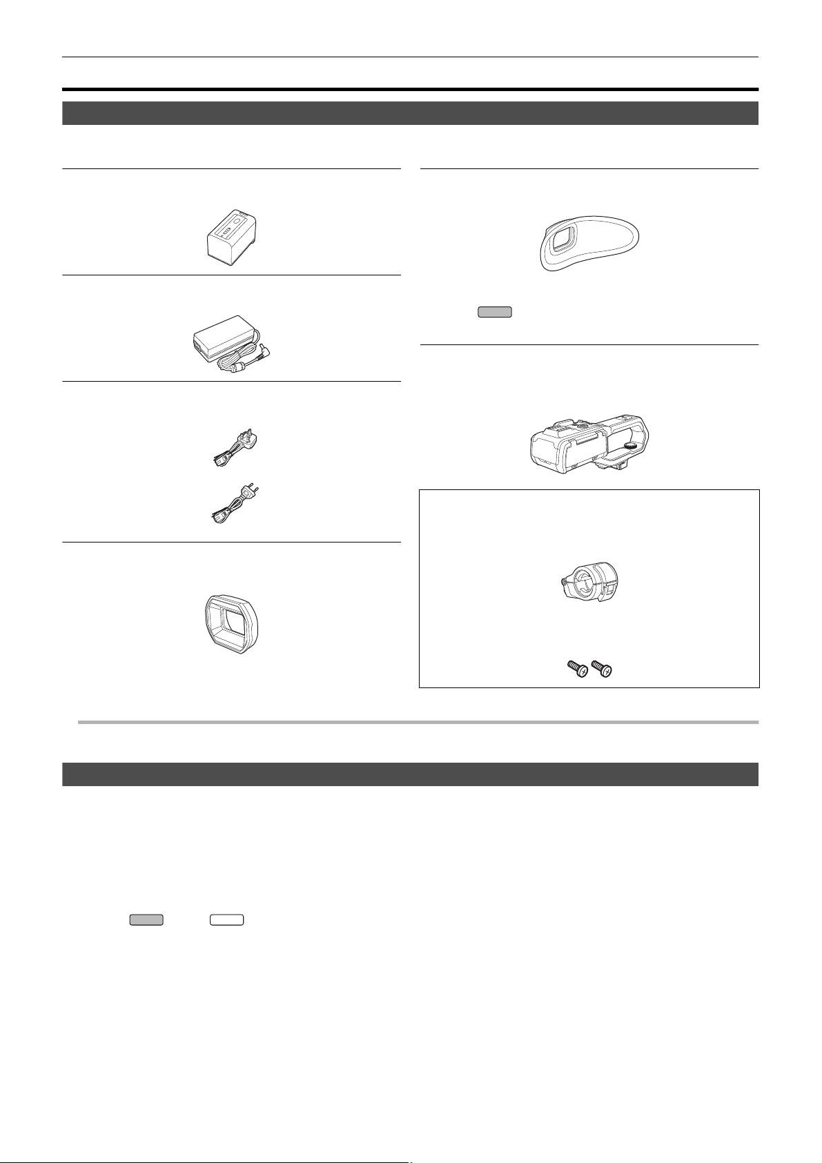
Check the accessories before using this unit.
Product numbers correct as of January 2020. These may be subject to change.
Battery pack (l 25)
AG-VBR59
AC adaptor (l 26)
SAE0011A
AC cable (l 26)
≥For AC adaptor
A
K2CT2YY00095
B
K2CQ2YY00117
Lens hood (l 28)
DVYE1189Z
≥Pre-attached to the main unit.
Eye cup (l 29)
DVZE1040Z
∫ For the
The following accessories are also supplied.
Handle unit (l 30)
VW-HU1
≥To purchase as a supplied accessory, use part number
when ordering.
1AC2HCX2500Z
Microphone holder (l 30)
≥The microphone holder mounting screws are supplied with the
microphone holder.
X2000
1KC1VWHU1EK
Microphone holder mounting screws (l 30)
1PP1HCX2500Z
≥Length 12 mm (×2)
≥ Appropriately discard the AC cable cap (if attached) and packing materials after taking the product out.
Optional accessories
Some optional accessories may not be available in some countries.
Product numbers correct as of January 2020. These may be subject to change.
¥Battery charger (AG-BRD50)
¥Battery pack (AG-VBR59, VW-VBD58)
¥LED video light (VW-LED1E)
¥Stereo microphone (VW-VMS10E)
¥Unidirectional microphone (AG-MC200G)
¥Handle unit (VW-HU1)
* Handle unit ( supplied, optional (VW-HU1)) required.
*
- 13 -
Chapter 1 Overview — When turning on the power for the first time
NOTE
NOTE
ヌパホパパ
ホ ハハ
When turning on the power for the first time
The time zone, date, and time are not set when the unit is shipped.
[TIME ZONE] is displayed in the LCD monitor when the power is turned on for the first time.
Follow the guidance and make the settings in the order of [TIME ZONE] and then [CLOCK SETTING].
≥ You can do these operations either with the multidial or by touching the LCD monitor.
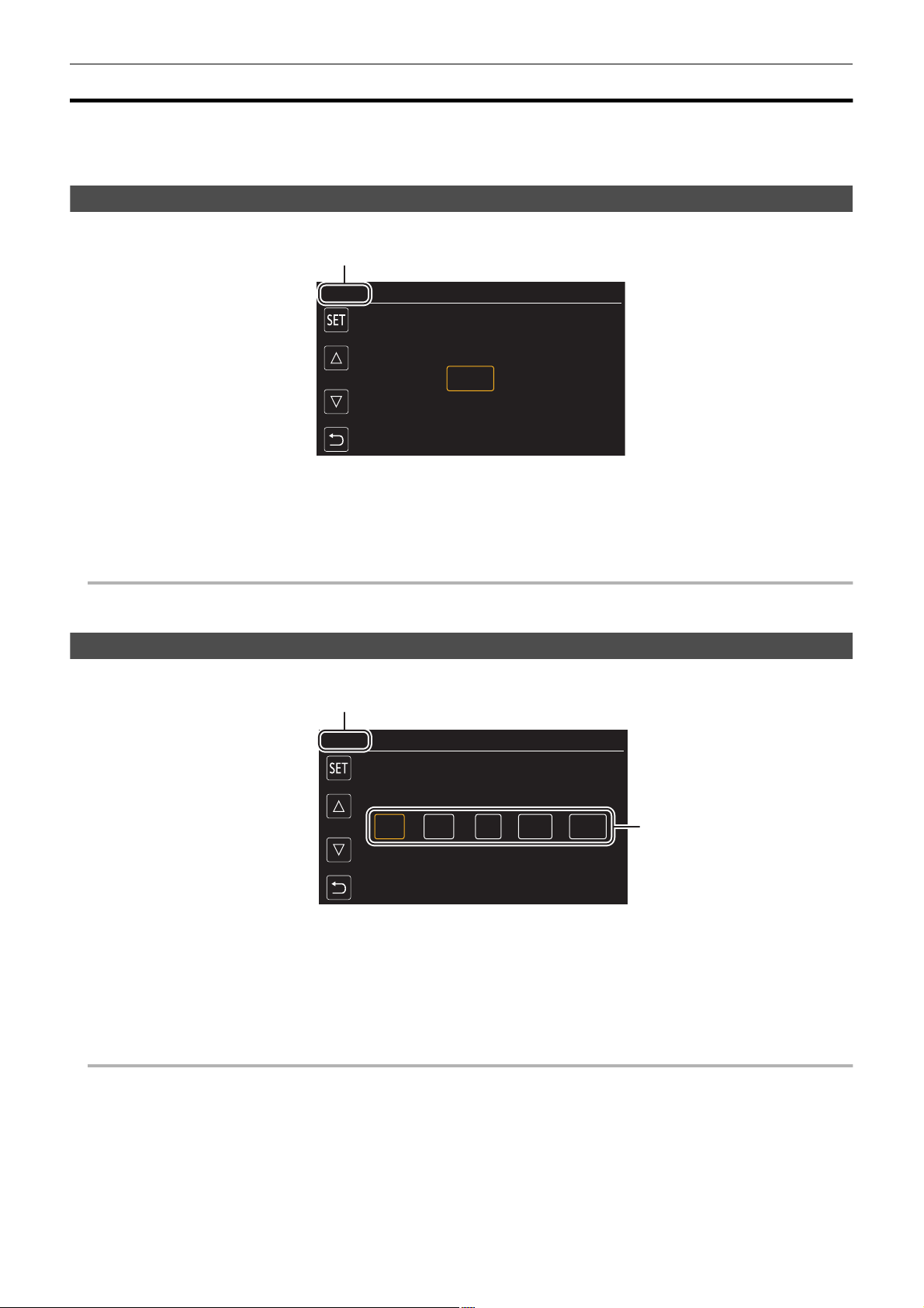
[TIME ZONE]
Set the time difference from the Greenwich Mean Time.
A [TIME ZONE]
1
Set the time difference.
2
Select [SET].
Once the setting for [TIME ZONE] is completed, the [CLOCK SETTING] screen is displayed.
0 The setting for the date/time of the main unit changes together with the time zone settings.
0 This can also be set with the [OTHERS] menu → [CLOCK] → [TIME ZONE].
[CLOCK SETTING]
Set the year, month, date, and time.
A [CLOCK SETTING]
B 0 : 0 1. JAN. 2020
1
Set the year, month, date, and time.
The year can be set between 2018 and 2037.
2
Select [SET].
Once the setting is complete, the camera image screen is displayed.
0 This can also be set with the [OTHERS] menu → [CLOCK] → [CLOCK SETTING].
- 14 -
Chapter 1 Overview — What you can do with this unit
X2000
X2000
X2000
What you can do with this unit
Recording to the memory card
Recording in following types is possible.
≥ MOV recording (UHD and FHD recording)
≥ MP4 recording (UHD and FHD recording)
≥ AVCHD recording
≥ Simultaneous recording
≥ Relay recording
≥ Interval recording
≥ Background recording
≥ Pre-recording
Linking to external devices
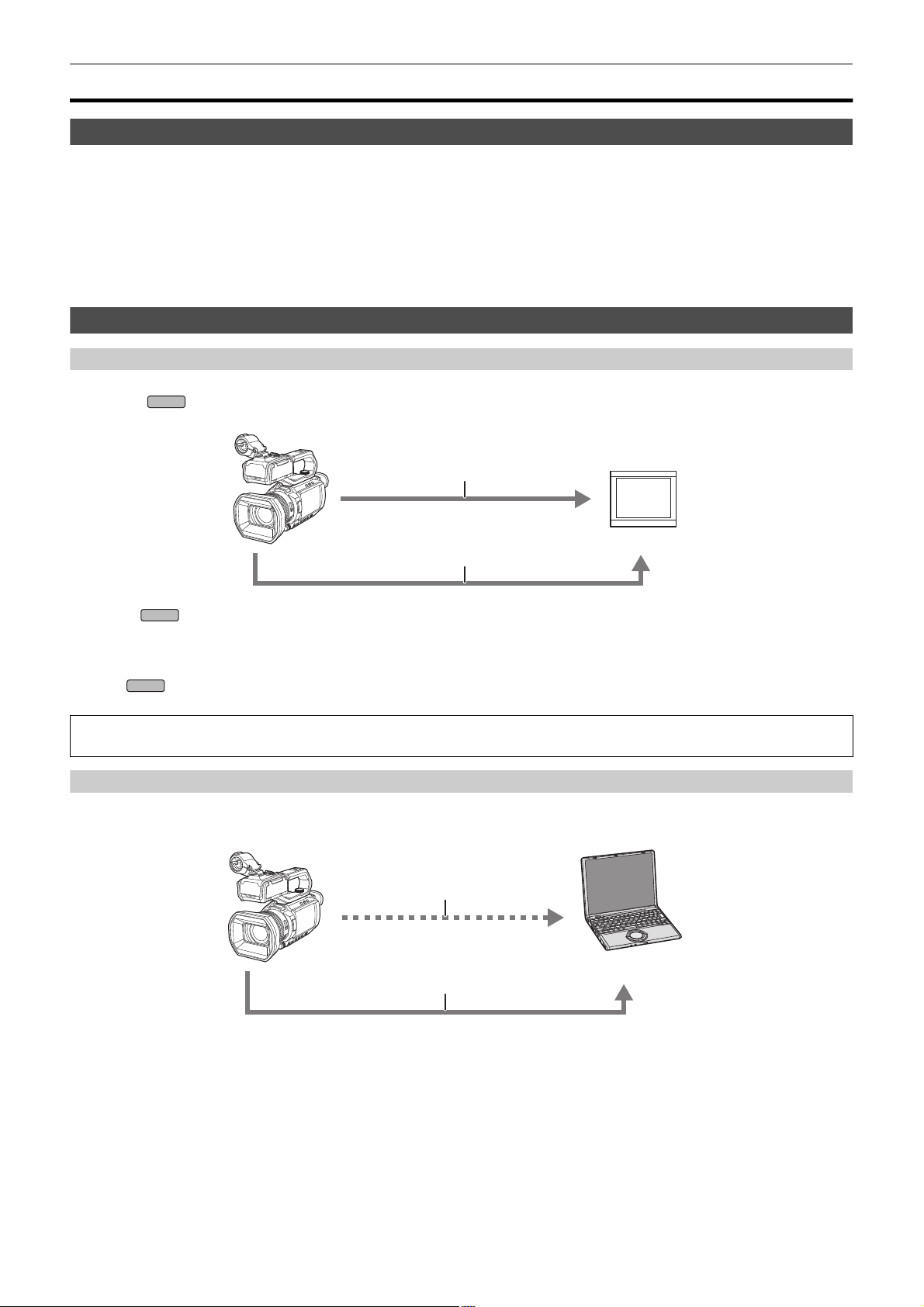
Connecting to TV/monitor
Connect to a TV/monitor and output images.
≥ When using , use a BNC cable (<SDI OUT> terminal) to connect a TV/monitor.
A HDMI cable
B (For the )
BNC cable (<SDI OUT> terminal)
C TV/Monitor
≥ Use a commercially-available High Speed HDMI cable. If possible, we recommend using a cable with a length of 3 m or less.
≥ (For the )
Use a commercially-available 5C-FB or equivalent double-shielded cable for the BNC cable.
When using a DVI converter, etc., to connect an HDMI cable to this unit, make sure that you connect last to the <HDMI> terminal on this unit.
Connecting first to the <HDMI> terminal on this unit may cause a malfunction.
Card reader mode
Data (files) for performing nonlinear editing on a computer are transferred.
≥ The unit supports USB2.0.
A Memory card
B USB2.0 cable
C Computer
*1 Memory cards are optionally available. They are not supplied with the unit.
*2 A USB2.0 cable is not supplied with the unit.
Use a commercially-available generic USB cable conforming to USB2.0. If possible, we recommend using a cable with a length of 1.5 m or less.
The unit does not offer a bus-powered function.
*1
*2
- 15 -

Chapter 1 Overview — What you can do with this unit
Connecting to the network
This unit is equipped with wireless LAN. It can connect to wireless LAN devices via a network.
Available functions
When the unit is connected to a network, the following functions are available.
∫ Connecting to HC ROP app
You can remotely control this unit with the HC ROP app by connecting this unit with an iPhone/iPad or Android terminal via wireless LAN.
≥ Checking camera status
≥ Camera remote control (focus, zoom, image quality settings, recording control such as start/end recording, and time code/user bits settings)
≥ Menu Operations
≥ Starting and stopping streaming (when the function is assigned to the USER button)
The unit supports the multi camera function, with which a camera selected from up to 8 cameras is remotely controlled from a single device.
For details about operation of the HC ROP app, refer to the online help for the app.
∫ Streaming function
You can perform streaming of audio and video currently shot with the unit over a network (wireless LAN).
- 16 -

Chapter 2
This chapter describes the names, functions, and operations of parts on the unit.
Description of Parts
Main unit
21 3 4 5
13 14 15
21
22
16
6
1211 17
23
24252627282930
8
7
10
9
201918
Chapter 2 Description of Parts — Main unit
The illustrations in this document show the handle unit ( supplied, optional) removed.
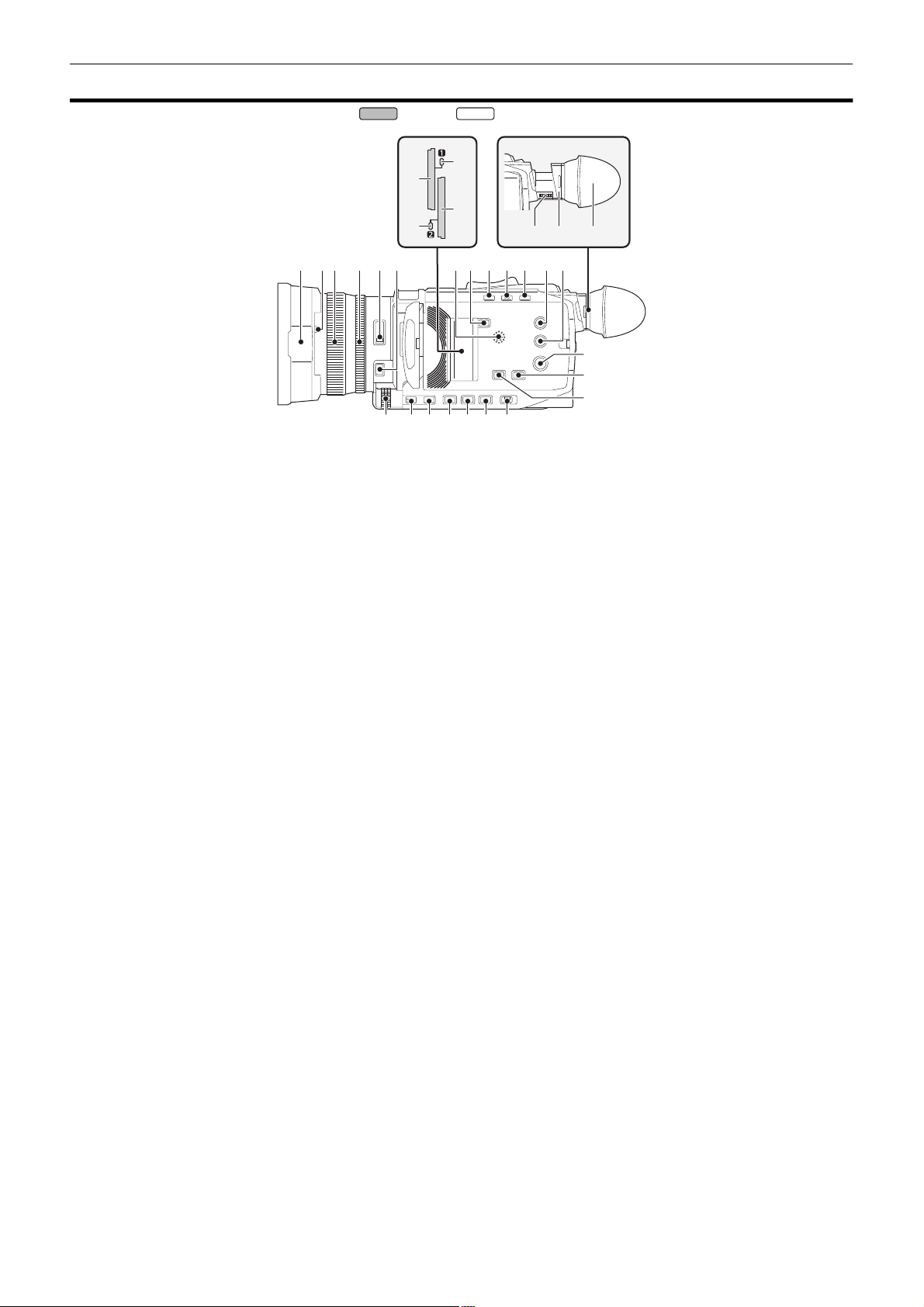
1
Lens hood (l 28)
2
Lens cover switching lever (l 29)
Opens/closes the lens cover.
3
Focus ring (l 108)
When the <FOCUS A/M/¶> button is pressed to set to manual focus
mode ([MF]) you can focus manually.
4
Rear ring (l 105, 107, 115)
You can manually perform zoom operations, adjust the iris (the lens
stop), and adjust the AE level (exposure compensation).
≥ You can switch the function to be adjusted by setting with the menu,
pressing the USER button assigned to [REAR RING], or touching
the USER button icon.
5
<ND FILTER> switch (l 108)
Selects the ND filter to suit the illumination of the subject.
<1/64>: Reduces the amount of light entering the MOS sensor to 1/64.
<1/16>: Reduces the amount of light entering the MOS sensor to 1/16.
<1/4>: Reduces the amount of light entering the MOS sensor to 1/4.
<CLR>: Does not use the ND filter.
6
<FOCUS A/M/¶> button (l 108)
Select the focus function.
[AF] and [MF] switch each time you press the button. The focal point
goes to infinity after you press and hold the button, and then the
manual focus mode is engaged.
[AF]: Changes to the auto focus mode. The auto focus mode adjusts
the focus automatically.
[MF]: Changes to the manual focus mode. Control the focus ring
manually to adjust the focus.
7
Card slot 1 (l 38)
A slot for the memory card.
8
Card 1 access lamp (l 38)
Indicates the access status for recording and playback of the memory
card inserted in card slot 1.
9
Card slot 2 (l 38)
A slot for the memory card.
10
Card 2 access lamp (l 38)
Indicates the access status for recording and playback of the memory
card inserted in card slot 2.
11
Built-in speaker
Outputs audio during playback.
Audio is not output from the built-in speaker when headphones are
connected to the headphone terminal.
12
<SLOT SEL> button
Selects the card slot to record to or play back from.
13
<USER1> button (l 47, 138)
Used as a USER button (USER1).
≥ [LEVEL GAUGE] is allocated at the time of purchase.
Switches display/hide of level gauge.
X2000 X1500
14
15
16
17
18
19
20
21
22
23
24
<USER2> button (l 47, 106)
Used as a USER button (USER2).
≥ [BACKLIGHT] is allocated at the time of purchase.
Switches enable/disable of the auto iris control function for backlight
compensation.
<O.I.S.>/<USER3> button (l 47, 135)
Switches enable/disable of the optical image stabilizer function.
This is also used as the USER button (USER3).
<THUMBNAIL> button (l 143)
Press the button to switch between the camera image screen and the
thumbnail screen.
<DISP/MODE CHK> button (l 162)
Switches display/hide of information other than the time counter, tim e
stamp, zebra pattern, and marker.
Press and hold the button to display information about the settings of
the various shooting functions and information such as a list of the
functions assigned to the USER button. Each press of the button
switches the information page in order.
Diopter adjustment dial (l 51)
Adjusts the diopter scale so that the viewfinder screen can be viewed
clearly.
Eyepiece
Do not leave the eyepiece pointed toward the sun. Doing so might
damage the devices inside.
Eye cup (l 29)
Power button (l 34)
Press the button to switch the power on/off.
<WHITE BAL> button (l 111)
Selects the method for adjustment of the white balance.
Each time you press the button, the white balance switches in the
order “Preset”, [Ach], [Bch].
“Preset”: Adjusts the white balance to the preset value. Each time you
either press the USER button assigned to [AWB] or touch the USER
button icon, the setting changes in the order [P 3200K], [P 5600K],
“VAR” (screen display example: [V 3200K]).
[Ach]/[Bch]: Selects when using the stored value for the adjustment of
the white balance.
<AE LEVEL>/<USER4> button (l 47, 107)
Switches enable/disable of the AE level function.
Set the target value of the AE level in the [SCENE FILE] menu →
[AE LEVEL EFFECT].
This is also used as the USER button (USER4).
<AUTO/MANU> switch (l 101)
Selects the method to adjust the focus, gain, iris, white balance, and
shutter speed at shooting.
<AUTO>: Adjusts automatically. (Auto mode)
<MANU>: Adjusts manually. (Manual mode)
- 18 -
Chapter 2 Description of Parts — Main unit
31 33
37
32
34
35
36
3938
40
41
25
<SHUTTER> button (l 109)
Switches the shutter mode.
26
<GAIN> button (l 106)
Selects the method for adjusting screen brightness.
27
<IRIS> button (l 105)
Selects the method for adjustment of the lens stop.
28
<MENU> button (l 57)
Displays the menu. Pressing the <MENU> button while the menu is
displayed closes the menu.
Press the button while the thumbnail screen is displayed to display the
operation screen of the thumbnail menu, and clips can be deleted.
29
<EXIT> button
Returns to one level higher when the menu is displayed. Pressing the
<EXIT> button without confirming the setting value will not reflect the
change in the setting.
30
Multidial (l 140)
Moves, selects, and sets the menu while the menu is displayed.
Use the multidial to also operate thumbnails, select the multi manual
function and select/set the various operation icons.
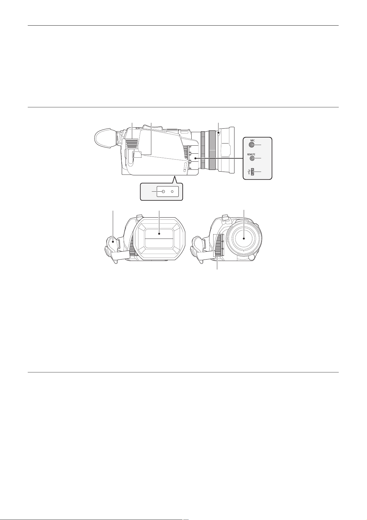
31
Fan inlet
Fan inlet for cooling fan. Do not block this while the unit is being used.
32
Wireless LAN Transmitter
33
Lens hood release button (l 28)
34
<MIC> terminal (l 33, 122)
Connect an external microphone (stereo mini jack).
35
<REMOTE> terminal
Connects the remote control unit (commercially-available) to control
some functions remotely.
36
USB terminal (l 167)
Connect to a computer with the USB2.0 cable to transfer data.
37
Tripod mounting holes (l 33)
Attach the tripod. (bottom)
≥ Mounting hole size
j 1/4-20 UNC (screw length 5.5 mm or shorter)
≥ Attaching a tripod with a screw length of 5.5 mm or more may
damage the unit.
38
Grip belt (l 28)
39
Lens cover (l 29)
40
Lens
41
Fan outlet
Fan outlet for cooling fan. Do not block this while the unit is being
used.
- 19 -
Chapter 2 Description of Parts — Main unit
52
4342 45 46
44
47
48
49
50
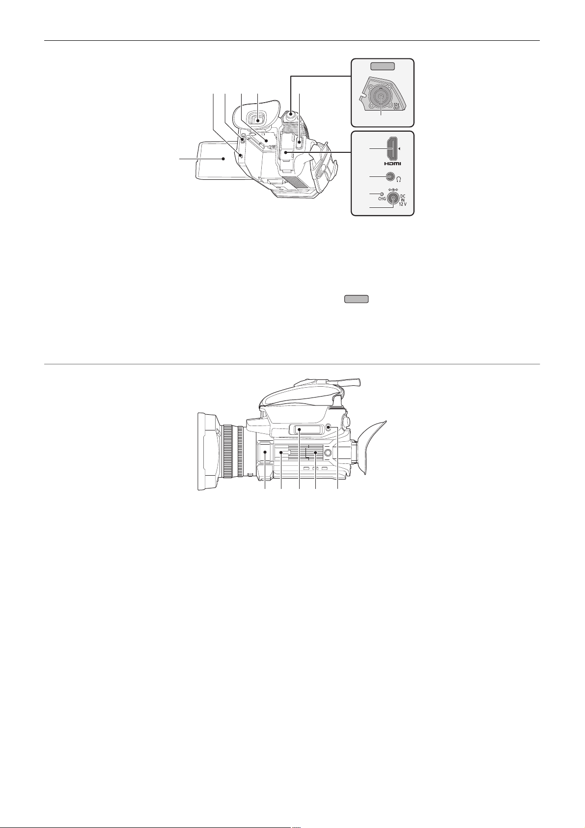
51
X2000
42
Status indicator (l 34)
Illuminates when power is on.
43
Battery release lever (l 25)
Used when removing the battery from the main unit.
44
Battery mounting section (l 25)
Attaches a battery.
45
Viewfinder (l 51)
46
REC button (on the grip) (l 101)
Starts or stops the recording.
It is possible to directly record from the thumbnail mode.
47
<HDMI> terminal (l 166)
A terminal to output video signal by connecting a monitor, etc.
48
Headphones terminal
Connects audio monitoring headphones.
49
Charging lamp (l 26)
Illuminates when the battery is charging.
50
<DC IN 12V> terminal (l 26)
Connects the supplied AC adaptor and supplies an external power.
51
(For the )
<SDI OUT> terminal (l 166)
A terminal to output SDI signal by connecting a monitor, etc.
52
LCD monitor (l 50)
X2000
53
Built-in microphone (l 122)
This is the built-in stereo microphone <L>/<R>.
54
Accessory shoe (on the main unit)
Attach a video light, etc.
55
Zoom lever (on the grip) (l 115, 150)
Adjusts the zoom of an image.
<T>: Zooms in the image.
<W>: Zooms out the image.
≥ Adjust the volume when playing back clips.
56
Handle unit mounting section (l 30)
57
<USER5> button (l 47, 102)
Used as a USER button (USER5).
≥ [REC CHECK] is set at the time of purchase.
Automatically plays back the last approximately 3 seconds of the
previously shot clip.
53 54 5655 57
- 20 -
Chapter 2 Description of Parts — Handle unit ([X2000] supplied, [X1500] optional: VW-HU1)
Handle unit ([X2000] supplied, [X1500] optional: VW-HU1)
1
8
9
1110
15 1214 13
A With a microphone holder attached
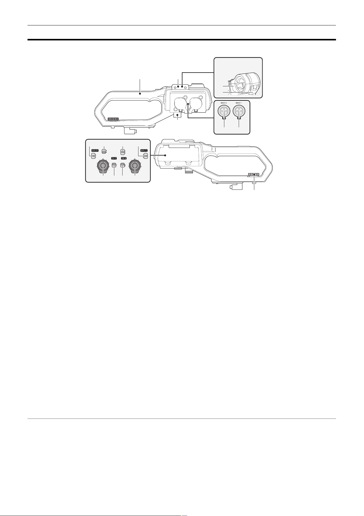
1
Handle
2
Microphone holder mounting section (l 30)
Attaches the supplied microphone holder with the microphone holder
mounting screws.
3
Microphone holder (l 30, 32)
Secures the external microphone in place.
4
Buckle (l 30, 32)
Used to open and close the microphone holder.
5
<INPUT 1> terminal (XLR, 3-pin) (l 32, 122)
Connects an audio equipment or an external microphone.
6
<INPUT 2> terminal (XLR, 3-pin) (l 32, 122)
Connects an audio equipment or an external microphone.
7
Microphone cable clamp (l 32)
Fixes the external microphone cable.
8
<INPUT1> switch (l 123)
Switches audio input signals connected to the <INPUT 1> terminal.
<LINE>: Select when audio equipment is connected by the line input.
<MIC>: Select when the external microphone is connected.
<i48V>: Select when the external microphone is connected and the
microphone needs a power supply.
9
CH1 SELECT switch (l 122)
Selects the audio to be recorded on audio channel 1.
<INT/MIC (L)>: Records left audio from the built-in microphone or
<MIC> terminal.
<INPUT1>: Records input signals from the <INPUT 1> terminal.
10
CH2 SELECT switch (l 122)
Selects the audio to be recorded on audio channel 2.
<INT/MIC (R)>: Records right audio from the built-in microphone or
<MIC> terminal.
<INPUT1>: Records input signals from the <INPUT 1> terminal.
<INPUT2>: Records input signals from the <INPUT 2> terminal.
2
3
4
7
6 5
16
11
<INPUT2> switch (l 123)
Switches audio input signals connected to the <INPUT 2> terminal.
<LINE>: Select when audio equipment is connected by the line input.
<MIC>: Select when the external microphone is connected.
<i48V>: Select when the external microphone is connected and the
microphone needs a power supply.
12
<AUDIO LEVEL CH2> dial (l 123)
Adjust the recording level of audio channel 2.
13
<CH2> switch (l 123)
Selects how the recording level for audio channel 2 is adjusted.
<AUTO>: Adjusted automatically.
<MANU>: Adjusted manually with the <AUDIO LEVEL CH2> dial.
14
<CH1> switch (l 123)
Selects how the recording level for audio channel 1 is adjusted.
<AUTO>: Adjusted automatically.
<MANU>: Adjusted manually with the <AUDIO LEVEL CH1> dial.
15
<AUDIO LEVEL CH1> dial (l 123)
Adjust the recording level of audio channel 1.
16
Handle unit mounting screw (l 30)
Secures the handle unit to the main unit.
- 21 -

Chapter 2 Description of Parts — Handle unit ([X2000] supplied, [X1500] optional: VW-HU1)
26 25 24
2120 22 23
17 18
19
17
Light cover
≥ Keep the Light cover out of reach of children to prevent swallowing.
18
Built-in LED light (l 117)
19
Tally lamp (l 52)
Illuminates when the recording is started. Flashes when the battery
level becomes low.
Whether or not to illuminate the lamp can be set in the menu.
20
Accessory shoe (on the handle)
Attach a video light, etc.
21
<LIGHT> switch (l 117)
Switches the built-in LED light on/off.
22
Hold lever
Disables the REC button (on the handle) when switched to <HOLD>.
23
REC button (on the handle) (l 101)
Starts or stops the recording.
24
Accessory mounting hole
Accessories can be attached.
≥ Mounting hole size
j 1/4-20 UNC (screw length 5.5 mm or shorter)
25
Zoom lever (on the handle) (l 115)
Adjust the zoom of an image.
<T>: Zooms in the image.
<W>: Zooms out the image.
≥ The zoom speed is controlled with this lever in a way different from
the way it is controlled with the zoom lever (on the grip).
26
Light dimmer dial (l 117)
Adjusts the brightness of the built-in LED light.
Turn to <i> to brighten, turn to <j> to dim.
- 22 -

Chapter 2 Description of Parts — Basic operation
NOTE
NOTE
Basic operation
Multidial operation
Operate the multidial on the main unit by turning it in vertical direction or pushing it.
≥ Turning the multidial in vertical direction will move the cursor.
≥ Pressing the multidial will select or confirm the item with cursor.
≥ Values of the menu or the pages of the thumbnail screen can be changed continuously by pressing and turning the multidial vertically to fix the setting.
0 For details about operating the menu, refer to “When operating with the multidial”. (l 59)
Touch operation of the LCD monitor
The LCD monitor can be operated by directly touching with a finger.
Do not touch the LCD monitor with a pointed hard object such as a ball point pen.
∫ Touching
An operation to press and release the LCD monitor. An item or icon can be selected, or an item can be executed.
≥ To select an icon, touch the center of the icon.
≥ It will not operate while touching a different location of the LCD monitor.
∫ Sliding
An operation to move a finger while touching the LCD monitor. Playback operation such as the skip playback or direct playback, etc. can be performed.
∫ Touching and holding
An operation to keep on pressing, then releasing the LCD monitor. Values of the menu or the pages of the thumbnail screen can be changed
continuously.
0 For details about operating the menu, refer to “When operating by touching the LCD monitor”. (l 60)
- 23 -

Chapter 3
Before you use the unit, attach the battery following the procedures in this chapter. The attaching of accessories is also described in this chapter.
Preparation
Chapter 3 Preparation — Power supply
Power supply
A battery or the supplied AC adaptor can be used as the power supply for the unit.
≥ The unit is compatible to following batteries. (As of January 2020)
jAG-VBR59 (supplied/optional, supports quick charging)
jVW-VBD58 (optional)
≥ AG-VBR59 supports quick charging. Use a battery charger (AG-BRD50: optional) to perform quick charging.
Attaching and removing the battery
¥Press the power button to turn off the unit. (l 34)
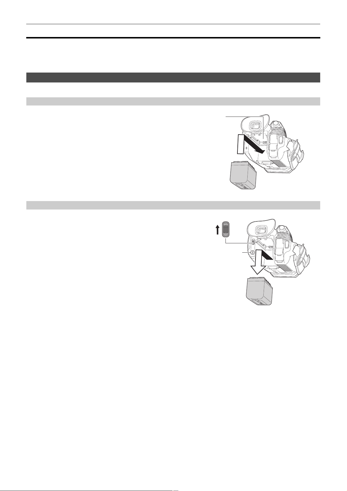
Attaching the battery
1
Push the battery against the battery mounting section on the main unit and
slide forward to attach.
Press in the battery until it clicks and gets locked.
A Battery mounting section
Removing the battery
Be sure to hold down the power button until the status indicator goes off. Then remove the
battery while supporting the unit to prevent it from dropping.
B Status indicator
Move the battery release lever in the direction indicated by
the arrow and remove the battery when unlocked.
- 25 -

Chapter 3 Preparation — Power supply
NOTE
Charging the battery
The battery is not charged at the time of purchase. Use only after charging sufficiently.
It is recommended that you have one extra battery.
≥ It is recommended to perform charging of the battery in a location with ambient temperature of 10 °C to 30 °C (same for the battery temperature).
≥ Use the supplied AC adaptor. Do not use the AC adaptor of another device.
≥ The supplied AC cable is dedicated for this unit. Do not use with any other device. Also, do not use AC cable from other device on this unit.
≥ The battery is not charged when the power is on.
1
Connect the AC cable to the AC adaptor and the AC outlet.
≥ Insert the plugs as far as they will go.
2
Connect the AC adaptor to the <DC IN 12V> terminal.
≥ As the charging lamp lights up green, charging starts. It will turn off
when the charging is completed.
≥ If the charging lamp flashes, refer to page 10.
≥ The DC plug of the AC adaptor, depending on its angle, may block
your view of the charging lamp. To check the charging lamp status,
adjust the angle of the DC plug.
∫ Connecting to the AC outlet
It is possible to use this unit with power supplied from the AC outlet by turning on the unit with the AC adaptor connected.
Even when you use the AC adaptor for recording images, keep the battery connected.
This allows you to continue the recording even if a power failure occurs or the AC adaptor is unplugged from the AC outlet by accident.
≥ The AC adaptor is in the standby condition when the mains plug is connected. The primary circuit is always “live” as long as the AC adaptor is
connected to an electrical outlet.
0 Do not use any other AC adaptors except the supplied one.
0 We recommend using Panasonic batteries (l 25).
0 If you use other batteries, we cannot guarantee the quality of this product.
0 Do not heat or expose to flame.
0 Do not leave the battery(ies) in a car exposed to direct sunlight for a long period of time with doors and windows closed.
0 Do not expose to low air pressure at high altitudes.
0 Do not expose to extremely low air pressure, as this may result in explosions or leakage of flammable liquids and gases.
- 26 -
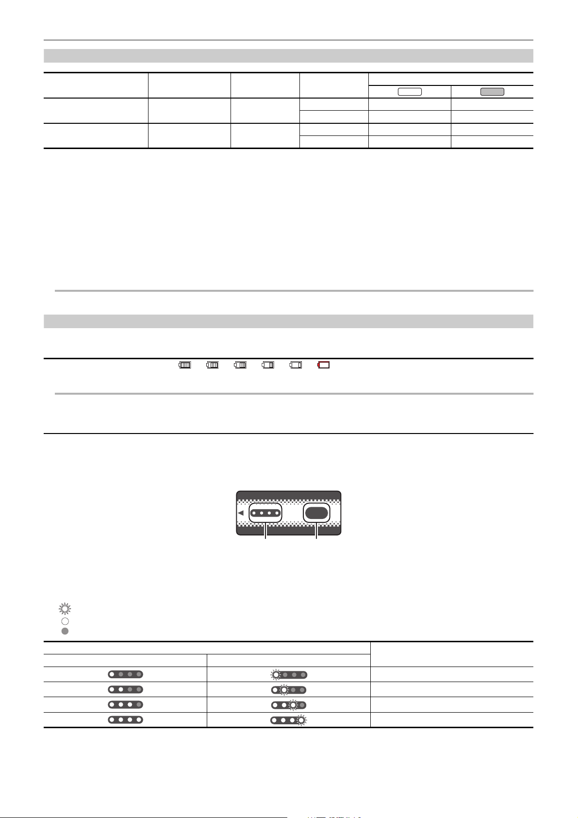
Chapter 3 Preparation — Power supply
NOTE
NOTE
X1500
X2000
ヤラユヤレヤラユヤレ
ヒパパ
テ
パ
1 2
Standard charging time and recordable time
Battery parts number
AG-VBR59 (supplied/optional) 7.28 V/5900 mAh Approx. 5 h 30 min [59.94Hz] Approx. 5 h 20 min Approx. 4 h 35 min
VW-VBD58 (optional) 7.2 V/5800 mAh Approx. 5 h 15 min [59.94Hz] Approx. 5 h 15 min Approx. 4 h 30 min
Voltage/capacity
(minimum)
Charging time for
main unit
[FREQUENCY]
[50.00Hz] Approx. 5 h 40 min Approx. 4 h 50 min
[50.00Hz] Approx. 5 h 35 min Approx. 4 h 45 min
Continuous recordable time
≥ “h” is an abbreviation for hour and “min” for minute.
≥ The charging time is the time when the operating ambient temperature is 25 °C and operating relative humidity is 60%. At other temperature and
humidity the charging time may take longer.
≥ Continuous recordable time is the time when the unit is used fulfilling all of the following conditions. If you use the unit in other conditions, continuous
recordable time will shorten.
jWhen set to the factory default menu settings ([FILE FORMAT] is [MOV] and [REC FORMAT] is [2160-59.94p/HEVC LongGOP 200M]/[2160-50.00p/
HEVC LongGOP 200M])
jWhen the LCD monitor is used and cable is not connected to the external input/output terminal
¥The charging time is the time to charge when the charging capacity of the battery is used up. The charging time or the continuous
recordable time differs depending on the use condition such as high or low temperature.
∫ Batteries that support quick charging
For quick charging of a battery (AG-VBR59: supplied/optional), use a battery charger (AG-BRD50: optional).
0 Battery is warm after using or after charging, but this is not a malfunction.
Checking the remaining battery level
The remaining battery level can be checked with the power status display on the LCD monitor or the indicator on the supplied battery.
Checking the remaining battery level with the LCD monitor
The battery status display will change as → → → → → while the remaining battery level gets lower. It will flash in red
when the remaining battery level is zero.
0 The power status display may not be displayed depending on the setting in the menu.
0 Repair or copy of the clip, or update of the firmware is not possible when it is flashing in red.
Checking the remaining battery level with the battery
≥ The remaining battery level can be checked with the indicator display by pressing the <CHECK> button on the battery when it is not charging.
jThe remaining battery level is a rough indication.
jThe indicator will not illuminate even if the <CHECK> button is pressed when the remaining battery level is zero. Charge the battery.
≥ The progress of the charging is notified by the flashing position of the indicator while the battery is charging.
Once the charging is completed, the indicator turns off.
1
Indicator
2
<CHECK> button
∫ Display of the indicator
≥ The color and illuminate/flashing status of the indicator indicated by the icon in the table are as follows.
j : Flashing in green
j : Illuminated in green
j : Off
Indicator display
When checking the remaining battery level Charging
Remaining battery level/charging progress
0% to 25%
25% to 50%
50% to 75%
75% to 100%
≥ Display of the indicator is a rough indication. If the battery is attached to the unit or the battery charger (optional), check the remaining level on the
device the battery is attached to. The remaining level may differ from the one displayed with the indicator on the battery.
- 27 -
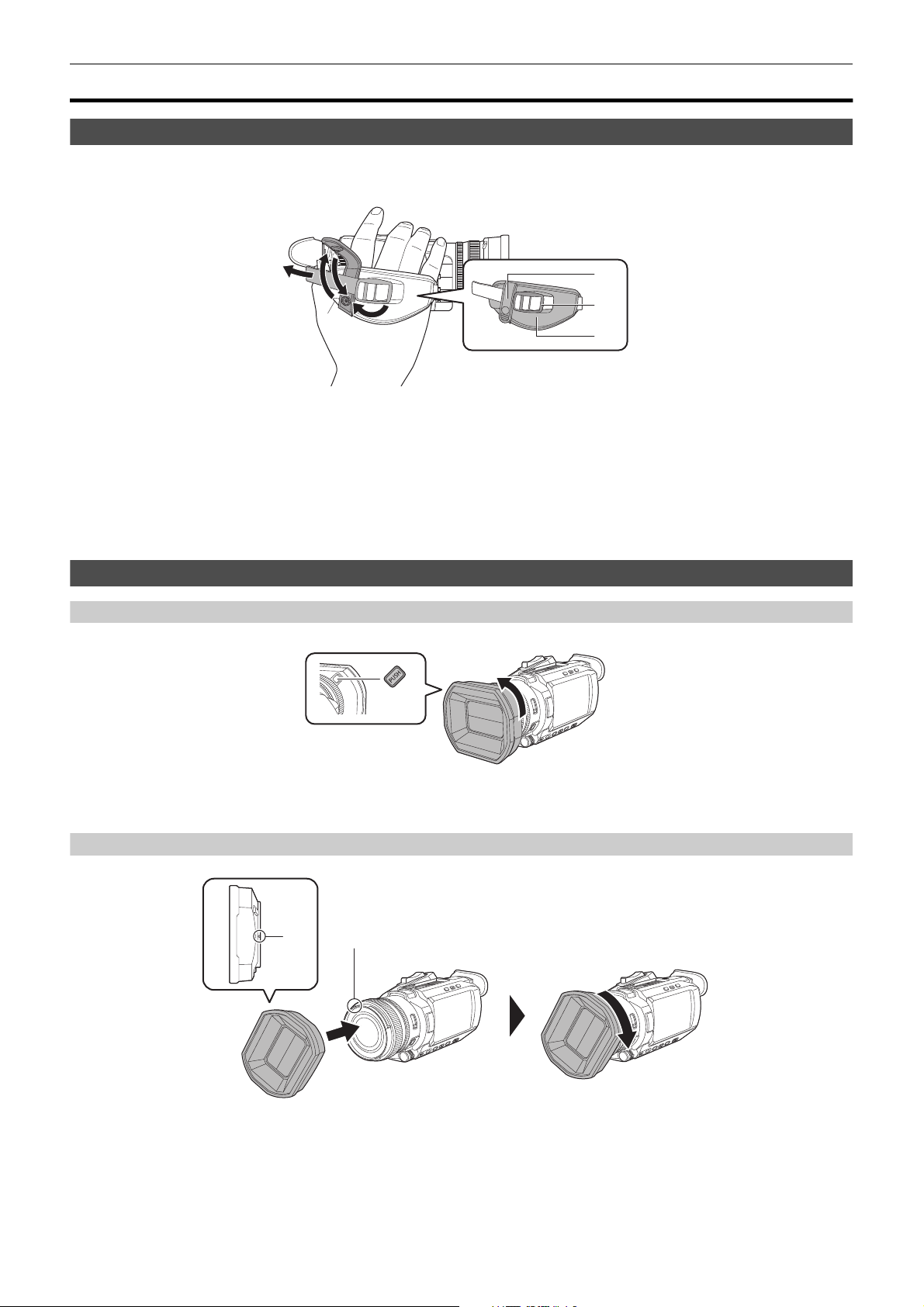
Chapter 3 Preparation — Attaching accessories
22
44
11
33
Attaching accessories
Adjusting the grip belt
≥ Adjust the grip belt so that it fits the size of your hand.
≥ If the buckle is difficult to tighten, move the pad backward and tighten the buckle again.
A Button
B Buckle
C Pad
1
Undo the button of the grip belt.
2
Open the buckle section.
3
Pull the end of the belt.
4
Do up the button of the grip belt.
Attaching the lens hood
Removing
A Lens hood release button
1
While pressing the lens hood release button, turn the lens hood in the direction of the arrow to remove it.
Attaching
B Mounting mark
1
Insert the lens hood into the unit.
≥ Align the mounting marks on the lens hood and unit.
2
Turn the lens hood clockwise.
≥ Turn until the lens clicks and locks into place.
- 28 -
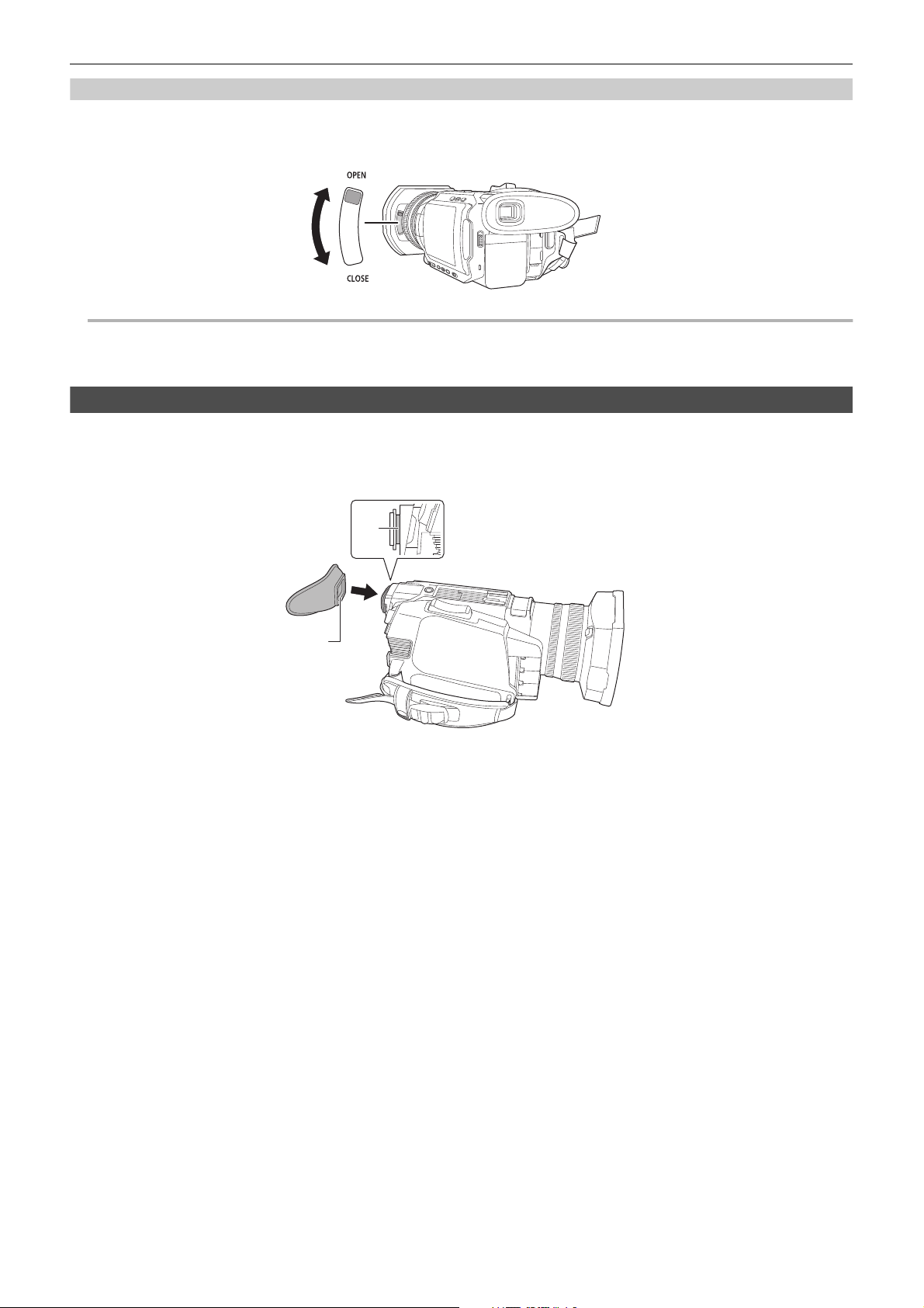
Chapter 3 Preparation — Attaching accessories
NOTE
Opening and closing the lens cover
Use the lens cover switching lever to open and close the lens cover.
Open the lens cover when shooting.
When not using the unit, close the lens cover in order to protect the lens.
0 Do not press the lens cover with force. Doing so may damage the lens and lens cover.
0 The lens cover may not open and close or the lens hood may not attach depending on the various filters and MC protectors mounted to the front lens of
the unit.
Attaching the eye cup
1
Attach the eye cup by aligning the groove on the mounting part of the eye cup with the inner ridge of the eye cup.
The illustration below is an example of attaching the eye cup to use it with your right eye.
If you rotate the eye cup to the left by 180° before attaching it, you can use it with your left eye.
A Groove
B Ridge
- 29 -
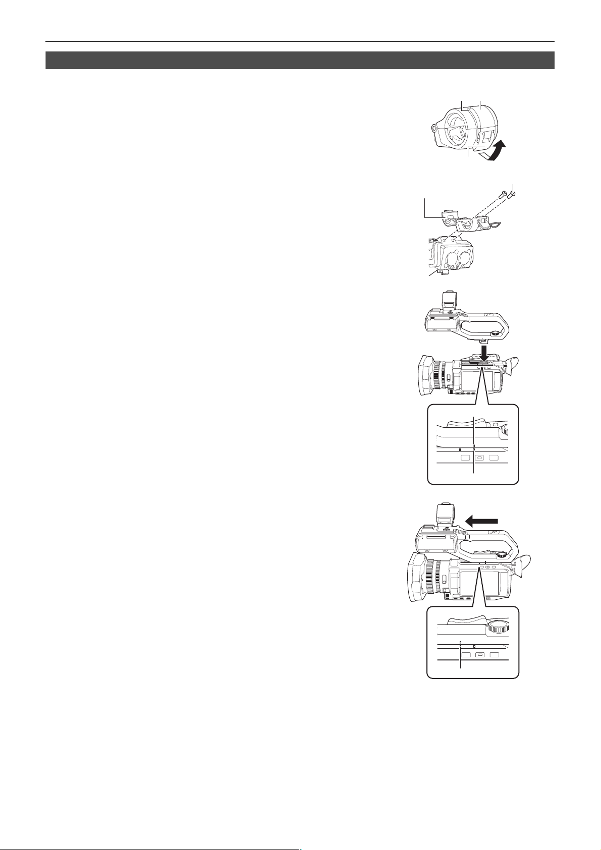
Chapter 3 Preparation — Attaching accessories
Attaching the handle unit ([X2000] supplied, [X1500] optional)
¥Press the power button to turn off the unit. (l 34)
1
Open the microphone holder.
Open buckle 1, and detach fitting 2 from hook 3.
2
Attach the microphone holder to the microphone holder mounting section on the
handle unit.
≥ Attach using a commercially-available screwdriver.
≥ There will be some rubbing noises with the rubber when screwing in the microphone holder
mounting screws, but please ensure they are done up tightly.
1 Microphone holder
2 Microphone holder mounting screws
3
Push the handle unit into the handle unit mounting section on the camera.
Match the positions of mounting mark A on the handle unit and mounting mark B on the
camera when pushing in.
4
Slide the handle unit in the direction indicated by the arrow.
Slide up to mounting mark C.
- 30 -
 Loading...