

Panasonic fv-xxvf2 Operation Manual
Ventilating Fan
FV-05VF2 FV-08VF2 FV-11VF2
READ AND SAVE THESE INSTRUCTIONS.R
Please
read
these
instructions
carefully
before
attempting
install,
to
operate or service the Panasonic Ventilating Fan. Failure to comply
with instructions could result in personal injury and/or property
damage. Please retain this booklet for future reference.
Table of Contents
Supplied Accessories
Description
Dimensions
Specifications
Unpacking
General Safety Information
Wiring Diagram
Installation
Installation
Installation
Installation
Installation
Installation
Maintenance
Practical Guide to Installation
Product Service
( Joist Mounting- )I
I
( Joist Mounting- )II
II
III
( -Joist Mounting )I
IV
( Between Joist Mounting )
( Wooden Header )
V
VI
( In Existing Construction )
2
2
3
4
4
4-5
5
6-8
8-9
10
10-11
12
12
13
14
14
FV-05VF2
FV-08VF2
FV-11VF2
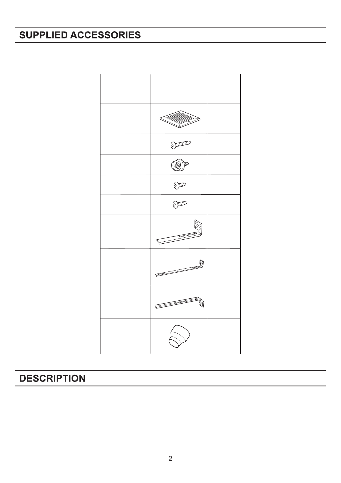
Part name
Grille
Long screw
(M4X30)
Thumb screw
Screw
I
(M4X8)
Screw
II
(M4X10)
Suspension
bracket I
Appearance
Quantity
1
8
1
2
2
1
Suspension
bracket II
Suspension
bracket III
1
1
3 inches adaptor
connector
1
(optional part)
These Panasonic ceiling mount ventilating fan models use a sirocco fan with dolphin-shaped blades driven by
a capacitor motor. The motor is designed to have an extended service life with reduced energy consumption.
Double orifice technology is used to reduce noise. It also incorporates a thermal-cutoff for safety. The grille
covering the main body is a spring-loaded, quickremove type. A damper for preventing counterflow is provided.
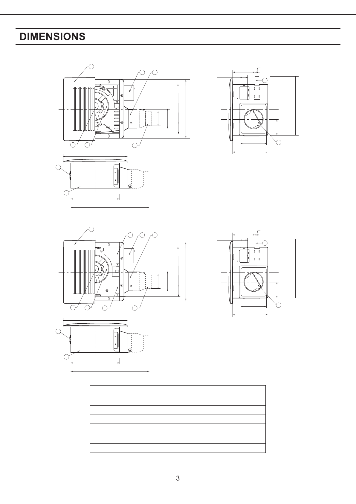
FV-05VF2
Unit: ( )inches mm
1
78
13 330()
12
3
4
11 7/8 (301)
10 1/4 259()
2 15/16 (74)
37/898()
5
1 (25)
3 5/8 (92)
1 3/4 (43.5)
43/8 110()
5 5/8 (141)
1(25)
9
3 1/4 (81)
13 1/4~15 1/2 ( 336~394 )
16 1/2~18 3/4 ( 419~480 )
21 1/4~23 1/2 ( 540~597 )
10
11
FV-08VF2 FV-11VF2
78
12
11
10 1/4 261()
16 1/8 (410)
1
13 330()
10 1/4 261()
16 1/8 (410)
43/8 110()
5 5/8 (141)
1 (25)
9
13 1/4~15 1/2 ( 336~394 )
16 1/2~18 3/4 ( 419~480 )
21 1/4~23 1/2 ( 540~597 )
3 1/4 (81)
10
2
3
4
11 7/8 (301)
10 1/4 259()
2 15/16 (74)
37/898()
6
5
1 (25)
3 5/8 (92)
1 3/4 (43.5)
No. No.
Blade
Grille
1
Orifice cover
2
Junction box
3
Adaptor
4
Adaptor connector
5
Orifice
6
7
Motor
8
Suspension bracket
9
Damper
10
Body
11
Bracket cover
12
(For 16 inches on center joists, only use suspension bracket , for 19.2 inches on center joists, only use
suspension bracket , If more than 19.2 inches on center,use suspension bracket & .)
III II III
Part namePart name
I
Duct
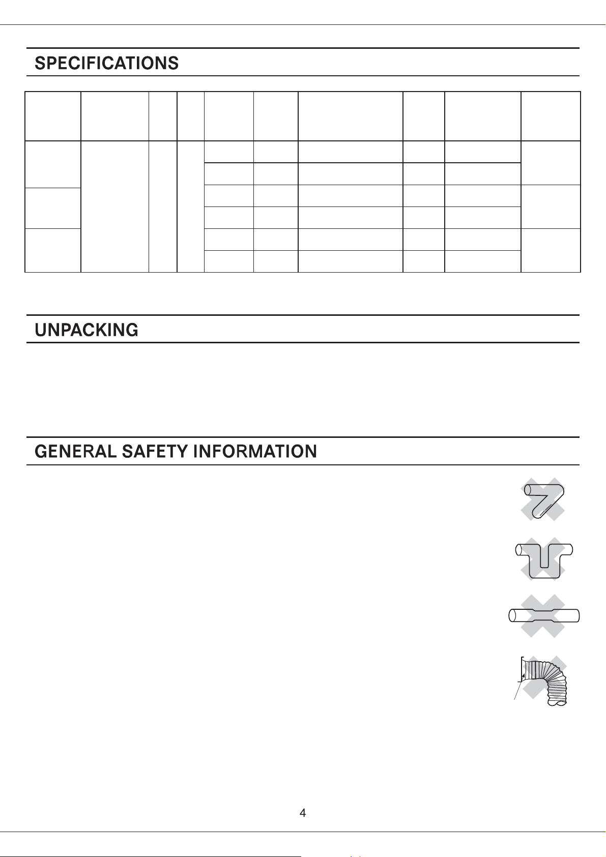
Air directionModel No.
Hz
V
diameter
(inches)
Noise
(sone)
Power consumption
(W)
Speed
(rpm)
Air deliver
(cfm)
Weight
(Ib.)
kg
3
0.5
15
FV-05VF2
0.4
0.8
0.8
1.5
15
24
24
33
FV-08VF2
Exhaust
120
4
3
60
4
3
FV-11VF2
4
1.5
33
Specifications are based on HVI standard.
Unpack and carefully remove unit from carton.
Refer to the Supplied Accessories list to verify that all parts are present.
635
755
830
50740
3.5 (7.7)
50
70845
3.7 (8.2)
80
901230
3.8 (8.4)
110
1. Do not install this ventilating fan where air temperature may exceed 40 C (104 F).
oo
2. Make certain that the electric service supply voltage is 120V, 60 Hz.
3. Follow all local electrical and safety codes, as well as the National Electrical Code (NEC) and
the Occupation Safety and Health Act (OSHA).
4. Always disconnect the power source before working on or near the fan, motor or junction box.
5. Protect the power cord from sharp edges, oil, grease, hot surfaces, chemicals or other objects.
6. Do not kink the power cord.
7. Do not install the unit where ducts are configured as shown in Fig. A.
8. Provide suction parts with proper ventilation.
9. This unit is UL listed for use over a bathtub or shower when installed in a GFCI protected
branch circuit.
Adaptor
Fig. A
(Cooking area)
Do not install above or
inside this area
CAUTION:
1. For general ventilating use only. Do not use to exhaust
hazardous or explosive materials and vapors.
2. Not for use in cooking area. (Fig. B)
3. This product must be properly grounded.
o
45
equipment
Cooking
Fig. B
45
o
Floor
WARNING:
To reduce the risk of fire, electric shock or injury to persons, observe the following;
A. Use this unit only in the manner intended by the manufacturer. If you have any questions, contact
the manufacturer.
B. Installation work and electrical wiring must be done by qualified person(s) in accordance with all
applicable codes and standards, including fire-rated construction.
C. Sufficient air is needed for proper combustion and exhausting of gases through the flue (chimney)
of fuel burning equipment to prevent backdrafting. Follow the heating equipment manufacturer's
guideline and safety standards such as those published by the National Fire Protection Association
(NFPA), and the American Society for Heating Refrigeration and Air Conditioning Engineers
(ASHRAE) and the local code authorities.
D. When cutting or drilling into wall or ceiling, do not damage electrical wiring and other hidden utilities.
E. Ducted fans must always be vented to the outdoors.
F. These models are UL listed for tub and shower enclosures.
G. Solid state controls may cause harmonic distortion which can cause motor humming noise. Do not use
this unit with any solid-state control device.
H. Before servicing or cleaning unit, switch power off at service panel and lock the service disconnecting
means to prevent power from being switched on accidentally. When the service disconnecting means
cannot be locked, securely fasten a prominent warning device, such as a tag, to the service panel.
I. NEVER place a switch where it can be reached from a tub or shower.
J. Not to be installed in a ceiling thermally insulated to a value greater than R40.
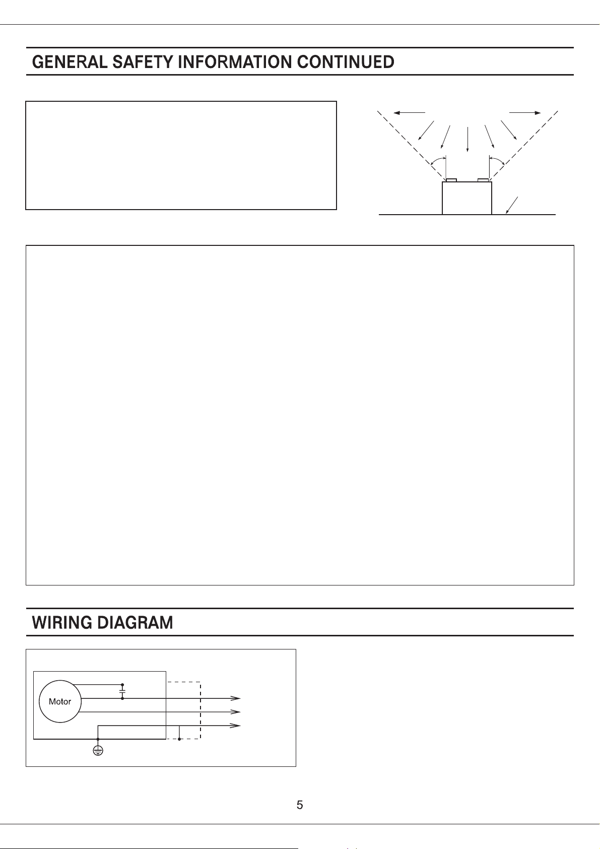
Fan unit
Red
White
Black
Capacitor
Green
Junction box
Green
Neutral
Live
Earth
Power Supply
AC120V 60Hz
Earth ground
 Loading...