

Page 1
INSTALLATION
INSTRUCTIONS
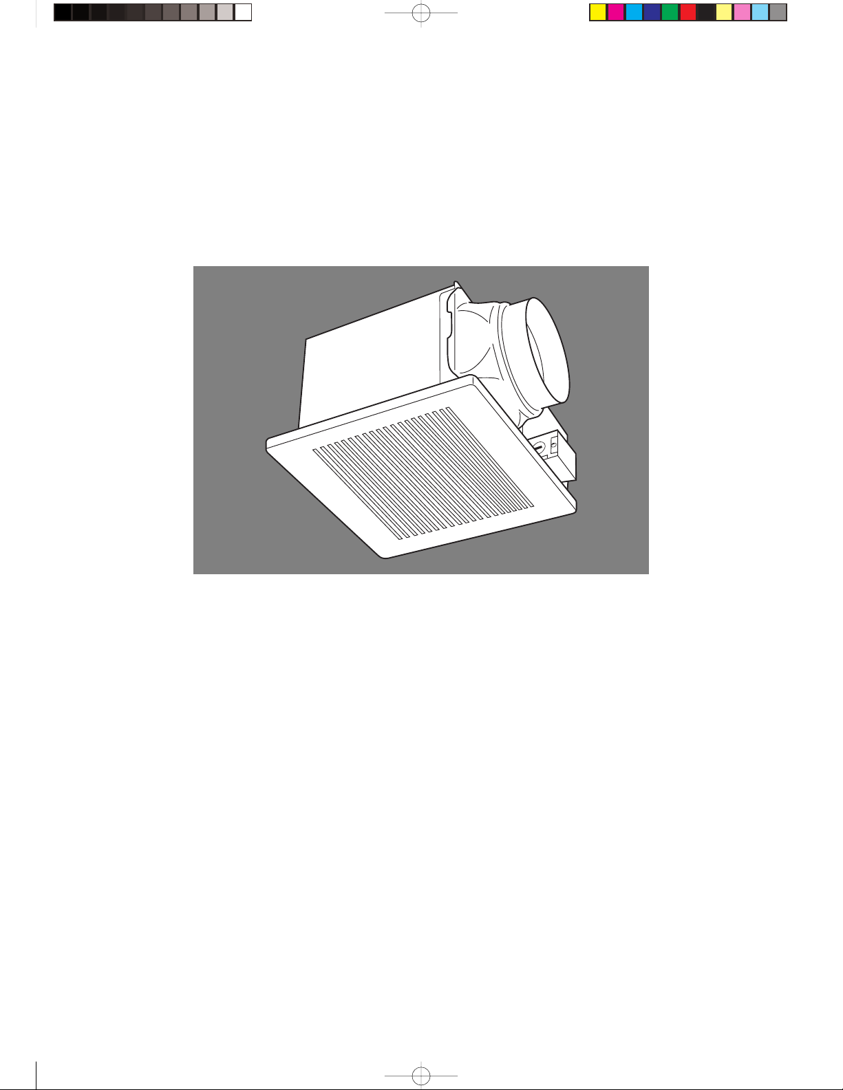
Ventilating Fan FV-20VQ3 FV-30VQ3 FV-40VQ3
Panasonic
READ AND SAVE THESE INSTRUCTIONS.
Please read these instructions carefully before attempting to install,
operate or service the Panasonic Ventilating Fan. Failure to comply
with instructions could result in personal injury and/or property
damage. Please retain this booklet for future reference.
Table of Contents
Supplied Accessories.......................................................................................... 2
Description .......................................................................................................... 2
Dimensions ......................................................................................................... 3
Specifications ...................................................................................................... 3
Unpacking ........................................................................................................... 3
General Safety Information ................................................................................. 4
Installation I (Suspended Ceiling)....................................................................... 5
Installation II (Wooden Header Installation) ....................................................... 6
Installation III (In Existing Construction) ............................................................. 7
Maintenance........................................................................................................ 7–8
Product Service .................................................................................................. 8
1
Panasonic_E 19/02/02, 11:24 AMPage 1 Adobe PageMaker 6.5C/PPC
Page 2
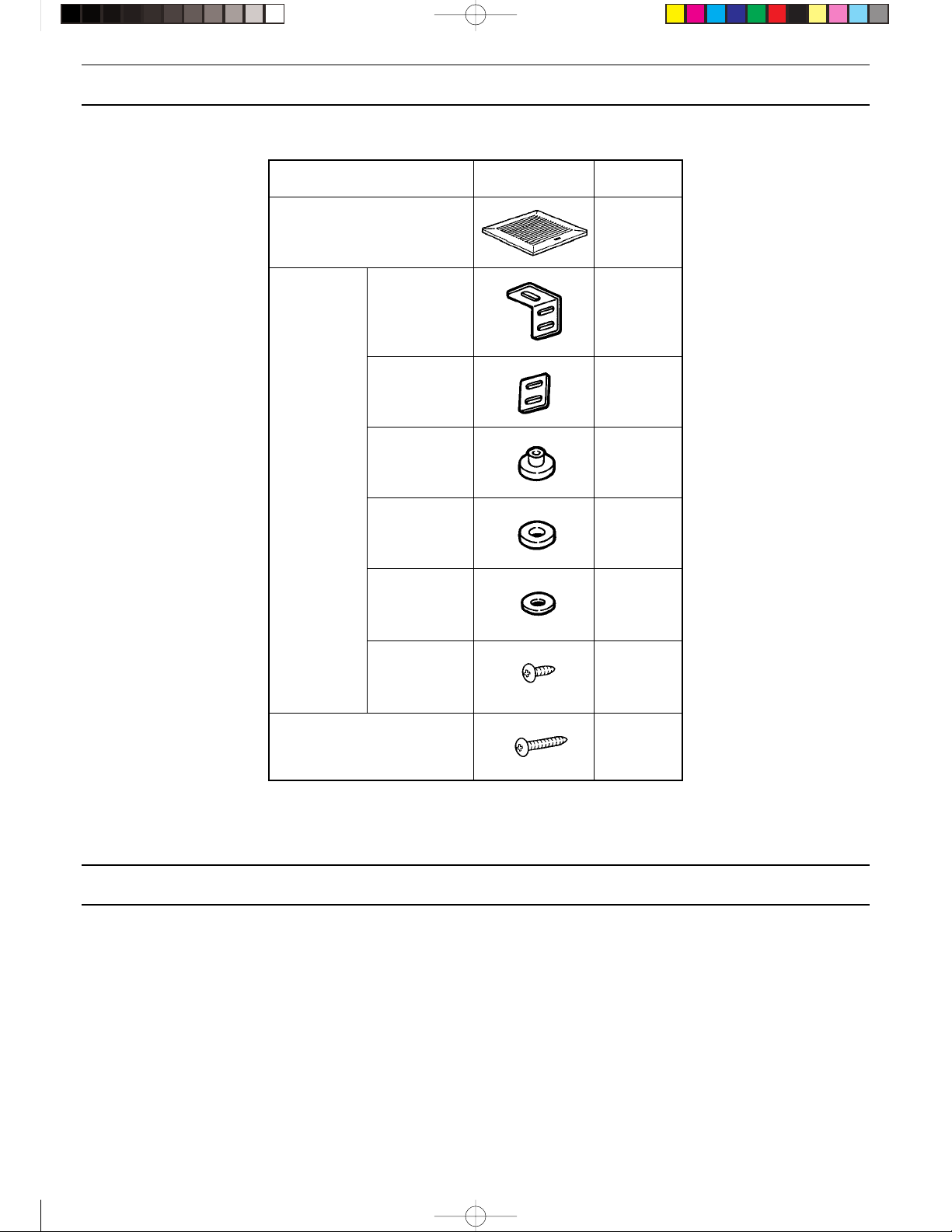
SUPPLIED ACCESSORIES
FV-20VQ3 FV-30VQ3 FV-40VQ3
Part name Appearance Quantity
Grille 1
Suspension
bracket set
Long screw 6
Suspension
bracket
Rubber 1 4
Rubber 2 4
Rubber 3 4
Washer 8
Screw 8
4
DESCRIPTION
These Panasonic ceiling mount ventilating fan models use a low noise sirocco fan driven by a capacitor motor.
The motor is designed to have an extended service life with reduced energy consumption.
It also incorporates a thermal-cutoff for safety. The grille covering the main body is a spring-loaded, quick-remove type.
A damper for preventing counterflow is provided.
2
Panasonic_E 19/02/02, 11:24 AMPage 2 Adobe PageMaker 6.5C/PPC
Page 3
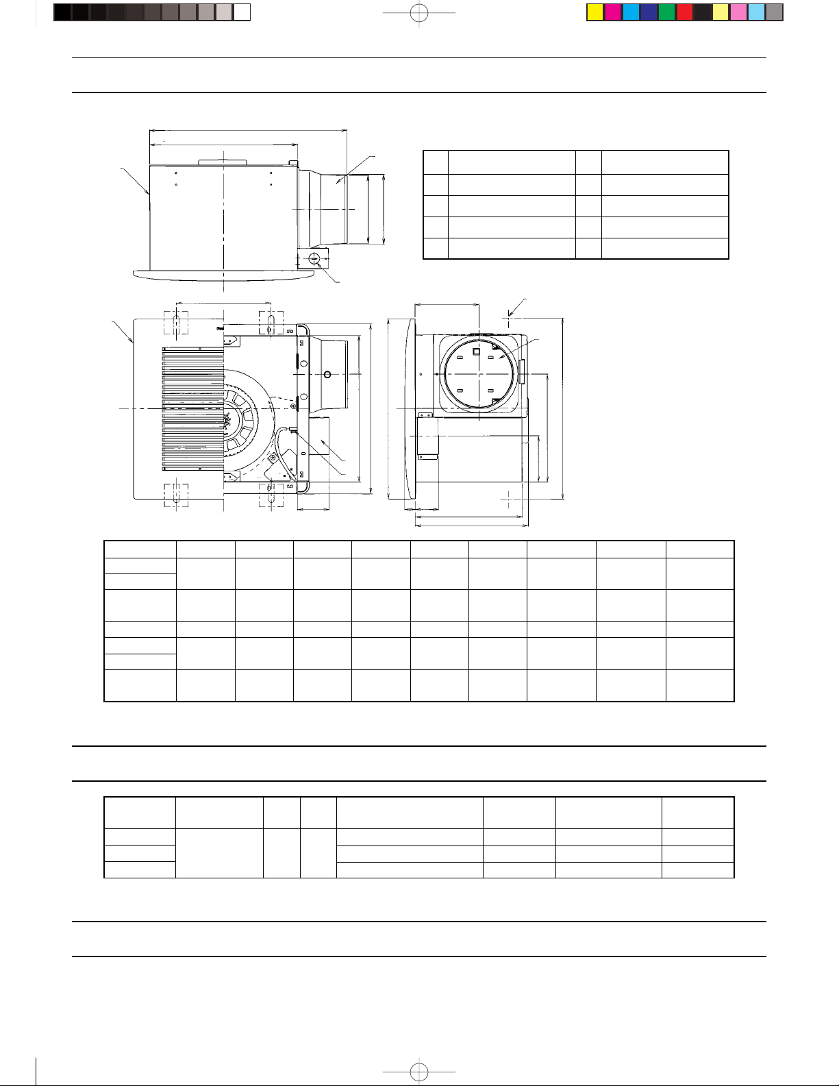
DIMENSIONS
FV-20VQ3 FV-30VQ3 FV-40VQ3
A
B
5
P
1
3
2
No. Part name No. Part name
1 Grille 5 Body
C
D
2 Adapter 6 Damper
3 Junction box 7 Plug connector
4 Junction box cover 8 Suspension bracket
N
8
6
I
H
G
Q
O
4
K
7
J
Model No. ABCDEF G H I
FV-20VQ3 420 312 142 146 236 22 380ⵧ 309ⵧ 357ⵧ
FV-30VQ3 (16 17/32) (12 9/32) (5 19/32) (5 3/4) (9 9/32) (7/8) (15ⵧ) (12 3/16ⵧ) (14 1/16ⵧ)
FV-40VQ3
Model No. J K L M N O P Q
FV-20VQ3 66 97 50 236 138 228 175–225 338–382
FV-30VQ3 (2 19/32) (3 13/16) (1 31/32) (9 5/16) (5 7/16) (8)
FV-40VQ3
484 376 142 146 236 22 450ⵧ 374ⵧ 422ⵧ
(19 9/16) (14 25/32) (5 19/32) (5 3/4) (9 9/32) (7/8) (17 11/16ⵧ) (14 23/32ⵧ) (16 5/8ⵧ)
66 161 50 250 138 292 235–285 403–447
(2 19/32) (6 11/32) (1 31/32) (9 27/32) (5 7/16) (11 1/2)
L
F
E
M
(6 7/8–8 7/8)
(9 5/16–11 7/32)
Dimensions: mm (inch)
(13 5/16–15 1/32)
(15 7/8–17 19/32)
SPECIFICATIONS
Model no. Air direction V Hz
FV-20VQ3 43.5 560 200 6.2 (13.6)
FV-30VQ3 Exhaust 120 60 66.5 730 300 6.7 (14.7)
FV-40VQ3 119 680 400 9.6 (21.1)
Power consumption Speed Air deliver at Weight
(W) (RPM) 0.1" WG (CFM) kg (lb.)
*At 0.0" Static pressure, (Pa)
UNPACKING
Unpack and carefully remove unit from carton.
Refer to the supplied accessories list to verify that all parts are present.
3
Panasonic_E 19/02/02, 11:24 AMPage 3 Adobe PageMaker 6.5C/PPC
Page 4

GENERAL SAFETY INFORMATION
1. Do not install this ventilating fan where air temperature may exceed 40°C. (104°F)
2. Make certain that the electric service supply voltage is 120V 60 Hz.
3. Follow all local electrical and safety codes, as well as the National Electrical Code (NEC) and the
Occupation Safety and Health Act (OSHA).
4. Always disconnect the power source before working on or near the fan, motor or junction box.
5. Protect the power cord from sharp edges, oil, grease, hot surfaces, chemicals, or other objects.
6. Do not kink the power cord.
7. Do not install the unit where ducts are configured as shown in Fig. A.
8. Provide suction parts with proper ventilation.
9. This unit is approved for use over a bathtub or shower when installed in a GFCI protected branch
circuit.
(Cooking area)
CAUTION
1. For general ventilating use only. Do not use to exhaust
hazardous or explosive materials and vapors.
2. Not for use in cooking area. (Fig. B)
3. This product must be properly grounded.
Do not install above
or inside this area.
Cooking
equipment
Fig. A
Floor
Fig. B
WARNING:
To reduce the risk of fire, electric shock, or injury to persons, observe the following:
A. Use this unit only in the manner intended by the manufacturer. If you have any questions, contact the
manufacturer.
B. Installation work and electrical wiring must be done by qualified person(s) in accordance with all applicable
codes and standards, including fire-rated construction.
C. Sufficient air is needed for proper combustion and exhausting of gases through the flue (chimney) of fuel
burning equipment to prevent backdrafting. Follow the heating equipment manufacturer’s guideline and safety
standards such as those published by the National Fire Protection Association (NFPA), and the American
Society for Heating Refrigeration and Air Conditioning Engineers (ASHRAE), and the local code authorities.
D. When cutting or drilling into wall or ceiling, do not damage electrical wiring and other hidden utilities.
E. Ducted fans must always be vented to the outdoors.
F. If this unit is to be installed over a tub or shower, it must be marked as appropriate for the application.
G. Do not use this unit with any solid-state control device.
H. Before servicing or cleaning unit, switch power off at service panel and lock the “service disconnecting mains”
to prevent power from being switched on accidentally. When the service disconnecting mains cannot be
locked, securely fasten a prominent warning device, such as a tag, to the service panel.
I. NEVER place a switch where it can be reached from a tub or shower.
J. Not to be installed in a ceiling thermally insulated to a value greater than R40.
4
Panasonic_E 19/02/02, 11:24 AMPage 4 Adobe PageMaker 6.5C/PPC
Page 5

INSTALLATION I (SUSPENDED CEILING)
1. Disconnect plug connector from receptacle before starting installation.
2. Assemble suspension bracket and rubber 1 to body.
(Fig. 1)
3. Suspend body with anchor bolts. (not supplied) (Fig. 2)
4. Remove junction box cover and secure conduit to junction box knockout hole. (7/8 inch) (Fig. 3)
5. Refer to wiring diagram
Using wire nuts, connect house power wires to ventilating fan wires (Fig. 3): black to black; white to white;
green to greens.
Replace junction box cover.
CAUTION
Mount junction box cover carefully so that lead
wires are not pinched.
Wiring Diagram
Motor
Thermal Cut Off
White
WhiteWhite
Live
Anchor bolt
Body
Screw
Suspension bracket
Rubber 1
Fig. 1
Anchor bolt (Not supplied)
Rubber
2 and 3
Red
Capacitor
Black BlackBlack
Power Supply
AC120V 60Hz
GreenGreen
Neutral
Earth
6. Install circular duct (6 inch) and secure it with tape.
7. Finish ceiling work. Ceiling hole should be aligned with
fan opening.
8. Connect plug connector to receptacle.
9. Insert mounting springs into slots as shown and mount
grille to fan body. (Fig. 4)
Junction box
Lead wires
Slot
Green wires
Washer
Anchor
bolt
Rubber 1
Conduit
Wire nut
Fig. 2
Fig. 3
Mounting spring
Grille
5
Panasonic_E 19/02/02, 11:25 AMPage 5 Adobe PageMaker 6.5C/PPC
Fig. 4
Page 6

INSTALLATION II (WOODEN HEADER)
1. Install header between ceiling joists using nails or
screws. (Fig. 5)
2. Install the ventilating fan to the header with long screws.
(Figs. 5 & 6)
mm (inch)
Model No. A B
FV-20VQ3 315 454
FV-30VQ3 (12 13/32) (17 7/8)
FV-40VQ3
380 518
(15) (20 13/32)
Ceiling joist
Ventilating fan
Header
Ceiling joist
Adapter
Fig. 5
3. Insert the circular duct to the adapter.
Remove the junction box cover and secure conduit to
junction box knockout hole. (7/8 inch) (Fig. 6)
4. Refer to wiring diagram.
Using wire nuts, connect house power wires to ventilat-
ing fan wires: black to black; white to white; green to
green. Replace junction box cover.
CAUTION
Mount junction box cover carefully so that lead
wires are not pinched.
Wiring Diagram
Motor
Thermal Cut Off
White
Red
Capacitor
Black BlackBlack
WhiteWhite
Power Supply
AC120V 60Hz
GreenGreen
Live
Neutral
Earth
Ceiling
Long screw
Adapter
Flange
Circular duct
Junction box cover
Fig. 6
Fig. 7
5. Finish ceiling work. Ceiling hole should be aligned with
the edge of the flange. (Fig. 7)
6. Mount grille to fan body. (Fig. 4 of page 5).
6
Panasonic_E 19/02/02, 11:25 AMPage 6 Adobe PageMaker 6.5C/PPC
Page 7

INSTALLATION III (IN EXISTING CONSTRUCTION)
Installing the ventilating fan in an existing building requires an accessible area (attic or crawl space) above the planned
installation location, or existing ducting and wiring.
1. To install the ventilating fan, follow the procedures described in Installation II. Take the following precautions before
installation.
CAUTION
Check area above planned installation location to be sure that:
1. Duct work can be installed and that area is sufficient for proper ventilation.
2. Wiring can be run to planned location.
3. No wiring or other obstructions will interfere with installation.
2. Inspect duct work and wiring before proceeding with installation.
3. Plan suitable location for ventilating fan (next to ceiling joist).
4. Before installation, ensure there is sufficient space available (no obstruction or interference).
MAINTENANCE
WARNING
Disconnect power source before working on unit. Routine maintenace of the fan must be done every year.
CAUTION
1. Never use petrol, benzene, thinner or any other such chemicals for cleaning the ventilating fan.
2. Do not allow water to enter motor.
3. Do not immerse resin parts in water over 60°C (140°F).
1. Remove grille. (Squeeze mounting spr ing and pull
down.) (Fig. 8)
Slot
Mounting spring
Glove
Grille
2. Wash and clean grille. (Use non-abrasive kitchen
detergent.) Wipe dry with new cloth. (Fig. 9)
7
Panasonic_E 19/02/02, 11:25 AMPage 7 Adobe PageMaker 6.5C/PPC
Fig. 9Fig. 8
Page 8

MAINTENANCE (CONT.)
3. Remove dust and dirt from fan body using a vacuum
cleaner. (Fig. 10)
4. Using a cloth dampened with kitchen detergent, remove
any dirt from fan body. Wipe dry with new cloth. (Fig. 11)
5. Replace grille.
Cleaner
Fig. 10
Fig. 11
PRODUCT SERVICE
Warning Concerning Removal of Covers.
This unit should be serviced by qualified technicians only. No service information is provided for customers. Your product
is designed and manufactured to ensure a minimum of maintenance. However, should your unit ever require service, a
nationwide system of factory service centers and AUTHORIZED INDEPENDENT SERVICE CENTER are maintained to
support your product’s warranty. (In the U.S.A., call 1-866-292-7292 to locate the Panasonic Authorized Service Center
nearest you.)
PANASONIC HOME AND COMMERCIAL PRODUCTS COMPANY
One Panasonic Way, Secaucus, NJ 07094
PANASONIC CANADA INC.
5770 Ambler Drive, Missisauga, Ontario L4W 2T3
8
Panasonic_E 19/02/02, 11:25 AMPage 8 Adobe PageMaker 6.5C/PPC
32CD54020EUL2-I0297-5
 Loading...