

Panasonic EYFMA1J User Manual [en, es, fr]
Operating Instructions
Instructions d’utilisation
Manual de instrucciones
Destornillador de impacto inalámbrico/Llave de impacto inalámbrica
Perceuse à impact sans l/Clé de serrage à impact sans l
Cordless Impact Driver/Cordless Impact Wrench
Model No: EYFLA4A / EYFLA4AR
EYFLA5A / EYFLA5AR
EYFLA5Q / EYFLA5QR
EYFLA6J / EYFLA6JR
EYFLA6P / EYFLA6PR
EYFMA1P
EYFMA1J
* Pictured: Cordless impact driver
* Image: Perceuse à impact sans l
* En la imagen: Destornillador de impacto inalámbrico
IMPORTANT
This manual contains safety information. Read manual completely before first using this product and save this
manual for future use.
IMPORTANT
Ce mode d’emploi contient des informations sur la sécurité. Lisez-le en entier avant d’utiliser le produit et
conservez-le pour référence.
IMPORTANTE
Este manual contiene información de seguridad. Lea completamente este manual antes de utilizar por primera
vez este producto, y guárdelo para poder consultarlo en el futuro.
Index
English: Page 4
Français: Page
20
Español: Página 38
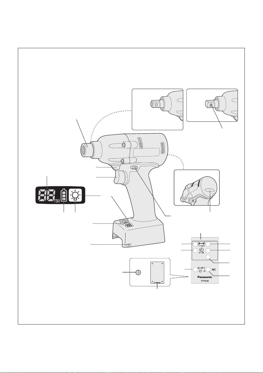
FUNCTIONAL DESCRIPTION
DESCRIPTION DES FONCTIONS
DESCRIPCIÓN FUNCIONAL
EYFLA4A/EYFLA4AR
EYFLA5A/EYFLA5AR
(I)
(G)(H)
(A)
(E)
(D)
(K)
(J)
(F)
(T)
EYFLA5QR
EYFLA5Q
EYFLA6J
EYFLA6JR
EYFMA1J
(C)
(V)
(U)
EYFLA6P
EYFLA6PR
EYFMA1P
(L)
(B)
(M)
(N)
(O)
(P)
(R)
(Q)
Remote control and battery are not included.
La télécommande et la batterie ne sont pas incluses.
El control remoto y la batería no están incluídos.
-
(S)
2 -

6.35 mm - (EYFLA4A, EYFLA4AR/EYFLA5A, EYFLA5AR)/square drive (EYFLA5Q, EYFLA5QR, EYFLA6J,
EYFLA6JR, EYFMA1J/pin type EYFLA6P, EYFLA6PR, EYFMA1P/pin-detent type)
6,35 mm -
(A)
EYFLA6JR, EYFMA1J/type à goujon EYFLA6P, EYFLA6PR, EYFMA1P/type à goupille d'arrêt)
6,35 mm EYFLA6JR, EYFMA1J/tipo pasador EYFLA6P, EYFLA6PR, EYFMA1P/tipo pasador retenedor)
Tightening conrmation lamp
Témoin de conrmation de serrage
(B)
Lámpara de conrmación de apriete
Alignment mark
Marques d’alignement
(D)
Marcas de alineación
Control panel
Panneau de commande
(F)
Panel de control
Battery indication lamp
Témoin indicateur de la batterie
(H)
Lámpara de indicadora de la batería
Variable speed control trigger
Gâchette de commande de vitesse
(J)
Disparador del control de velocidad variable
Pin-detent
Goupille d'arrêt
(L)
Pasador retenedor
+ button
Bouton +
(N)
Botón +
OK button
Bouton OK
(P)
Botón OK (correcto)
Format button
Bouton de format
(R)
Botón de formato
Battery
Batterie
(T)
Batería
Torque set button
Bouton de réglage du couple de serrage
(V)
Botón de ajuste de par de torsión
(EYFLA4A, EYFLA4AR/EYFLA5A, EYFLA5AR)/entraînement carré (EYFLA5Q, EYFLA5QR, EYFLA6J,
(EYFLA4A, EYFLA4AR/EYFLA5A, EYFLA5AR)/excitador cuadrado (EYFLA5Q, EYFLA5QR, EYFLA6J,
Forward/Reverse lever
Levier d’inversion marche avant/marche arrière
(C)
Palanca de avance/marcha atrás
Remote control Assembly Qualier
Véricateur d'assemblage de la télécommande
(E)
Cualicador incorporado con control remoto
LED light on/off button
Bouton Marche/Arrêt de la lumière DEL
(G)
Botón ON/OFF de luz LED
Display
Afchage
(I)
Visor
LED light
Lumière DEL
(K)
Luz indicadora
Remote control
Télécommande
(M)
Control remoto
− button
Bouton −
(O)
Botón −
Torque level button
Bouton de niveau du couple de serrage
(Q)
Botón de palanca de par de torsión
Holder
Support
(S)
Retenedor
Interval set button
Bouton de réglage de l’intervalle
(U)
Botón de ajuste de intervalo
-
3 -

I
.
GENERAL SAFETY
RULES
WARNING! Read all instructions
Failure to follow all instructions listed
below may result in electric shock, fire
and/or serious injury. The term “power
tool” in all of the warnings listed below
refers to your mains operated (corded)
power tool and battery operated
(cordless) power tool.
SAVE THESE INSTRUCTIONS
Work Area Safety
1) Keep work area clean and well lit.
Cluttered or dark areas invite accidents.
2)
Do not operate power tools in explosive
atmospheres, such as in the presence
of flammable liquids, gases or dust.
Power tools create sparks which may
ignite the dust or fumes.
3)
Keep children and bystanders away
while operating a power tool.
Distractions can cause you to lose control.
Electrical Safety
1) Power tool plugs must match the
outlet. Never modify the plug in any
way. Do not use any adapter plugs
with earthed (grounded) power tools.
Unmodified plugs and matching outlets
will reduce risk of electric shock.
2
) Avoid body contact with earthed or
grounded surfaces such as pipes,
radiators, ranges and refrigerators.
There is an increased risk of electric shock
if your body is earthed or grounded.
3) Do not expose power tools to rain or
wet conditions.
Water entering a power tool will increase
the risk of electric shock.
4)
Do not abuse the cord. Never use
the cord for carrying, pulling or
unplugging the power tool. Keep
cord away from heat, oil, sharp edges
or moving parts.
Damaged or entangled cords increase
the risk of electric shock.
5)
When operating a power tool outdoors,
use an extension cord suitable for
outdoor use.
Use of a cord suitable for outdoor use
reduces the risk of electric shock.
Personal Safety
1)
Stay alert, watch what you are doing
and use common sense when operating
a power tool. Do not use a power tool
while you are tired or under the influence
of drugs, alcohol or medication.
A moment of inattention while operating
power tools may result in personal injury.
2
) Use safety equipment. Always wear
eye protection.
Safety equipment such as dust mask,
non-skid safety shoes, hard hat, or
hearing protection used for appropriate
conditions will reduce personal injuries.
3)
Avoid accidental starting. Ensure the
switch is in the off position before
plugging in.
Carrying power tools with your finger on
the switch or plugging in the power tools
that have the switch on invites accidents.
4)
Remove any adjusting key or wrench
before turning the power tool on.
A wrench or a key left attached to a
rotating part of the power tool may result
in personal injury.
5)
Do not overreach. Keep proper
footing and balance at all times.
This enables better control of the power
tool in unexpected situations.
6)
Dress properly. Do not wear loose
clothing or jewellery. Keep your
hair, clothing and gloves away from
moving parts.
Loose clothes, jewellery or long hair can
be caught in moving parts.
7)
If devices are provided for the
connection of dust extraction and
collection facilities, ensure these are
connected and properly used.
Use of these devices can reduce dust
related hazards.
Power Tool Use and Care
1)
Do not force the power tool. Use the
correct power tool for your application.
The correct power tool will do the job
better and safer at the rate for which it
was designed.
2
) Do not use the power tool if the
switch does not turn it on and off.
Any power tool that cannot be controlled
with the switch is dangerous and must
be repaired.
3)
Disconnect the plug from the power
source and/or the battery pack from
-
4 -

the power tool before making any
adjustments, changing accessories,
or storing power tools.
Such preventive safety measures
reduce the risk of starting the power tool
accidentally.
4)
Store idle power tools out of the reach
of children and do not allow persons
unfamiliar with the power tool or these
instructions to operate the power tool.
Power tools are dangerous in the hands
of untrained users.
5)
Maintain power tools. Check for
misalignment or binding of moving
parts, breakage of parts and any other
condition that may affect the power
tools operation. If damaged, have the
power tool repaired before use.
Many accidents are caused by poorly
maintained power tools.
6)
Keep cutting tools sharp and clean.
Properly maintained cutting tools with
sharp cutting edges are less likely to
bind and are easier to control.
7)
Use the power tool, accessories
and tool bits etc. in accordance with
these instructions and in the manner
intended for the particular type of
power tool, taking into account the
working conditions and the work to
be performed.
Use of the power tool for operations
different from those intended could
result in a hazardous situation.
Battery Tool Use and Care
1) Ensure the switch is in the off position
before inserting battery pack.
Inserting battery pack into power tools
that have the switch on invites accidents.
2
) Recharge only with the charger
specified by the manufacturer.
A charger that is suitable for one type
of battery pack may create a risk of fire
when used with another battery pack.
3)
Use power tools only with specifically
designated battery packs.
Use of any other battery packs may
create a risk of injury and fire.
4)
When battery pack is not in use, keep it
away from other metal objects like paper
clips, coins, keys, nails, screws, or other
small metal objects that can make a
connection from one terminal to another.
Shorting the battery terminals together
may cause burns, or a fire.
5)
Under abusive conditions, liquid may
be ejected from battery; avoid contact.
If contact accidentally occurs, flush
with water. If liquid contacts eyes,
additionally seek medical help.
Liquid ejected from the battery may
cause irritation or burns.
Service
1) Have your power tool serviced by a
qualified repair person using only
identical replacement parts.
This will ensure that the safety of power
tool is maintained.
II
. INTENDED USE
This tool is a Cordless Impact Driver/Wrench
and can be used to tighten bolts, nuts, and
screws. Additionally, it provides a torque control
function that automatically stops tool operation
when a preset load is reached to deliver consistent tightening torque. Additionally, a separately
available Assembly Qualier can provide wireless monitoring to determine whether tightening
has been completed properly.
Read “the Safety Instructions” booklet
and the following before using.
III
.
ADDITIONAL SAFETY
RULES
1
) Wear ear protectors when using the
tool for extended periods.
2
) Be aware that this tool is always in an
operating condition, since it does not have
to be plugged into an electrical outlet.
3)
Hold power tools by insulated gripping
surfaces when performing an operation
where the cutting tool may contact hidden wiring or its own cord.
ontact with a “live” wire will make exposed
C
metal parts of the tool “live” and shock the
operator.
4)
Do NOT operate the Forward/Reverse
lever when the main switch is on. The battery will discharge rapidly and damage to
the unit may occur.
5)
During charging, the charger may become
slightly warm. This is normal.
D
o NOT charge the battery for a long period.
6) When storing or carrying the tool, set the
Forward/Reverse lever to the center position (switch lock).
-
5 -
7) Do not strain the tool by holding the speed
control trigger halfway (speed control
mode) so that the motor stops.
Symbol Meaning
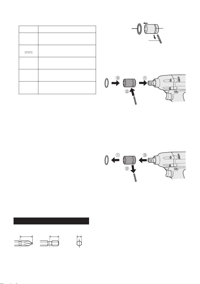
Attaching Socket (Pin type)
• Remove the socket’s rubber ring and pin.
rubber
ring
groove
V
n
0
Revolutions or reciprocations
-1
… min
Ah
IV
. ASSEMBLY
Electrical capacity of battery
Volts
Direct current
No load speed
per minutes
pack
Attaching or Removing Bit
NOTE:
•
When attaching or removing a bit, disconnect battery pack from tool or place the
switch in the center position (switch lock).
1. Hold the collar of quick connect chuck and
pull it out from the tool.
2
. Insert the bit into the chuck. Release the
collar.
The collar will return to its original position
3.
when it is released.
Pull the bit to make sure it does not come out.
4.
5. To remove the bit, pull out the collar in the
same way.
CAUTION:
•
If the collar does not return to its origi-
nal position or the bit comes out when
pulled on, the bit has not been properly
attached. Make sure the bit is properly
attached before use.
EYFLA4A/EYFLA4AR/EYFLA5A/EYFLA5AR
12 mm
(15/32")
9 mm – 9.5 mm
(
23/64" – 3/8")
6.35 mm
(1/4")
pin
1 Attach the socket to the tool.
2 Insert
3 A
the pin. (Taking care to align the pin
holes on the socket and tool.)
ttach the rubber ring by sliding it into place
over the groove.
NOTE:
Be sure to attach the rubber ring to prevent
the pin from falling out.
Removing Socket (Pin type)
1 Remove the rubber ring.
2 Remove the pin.
emove the socket from the tool.
3 R
NOTE:
Keep the temperature of the tool above
the
freezing point (0°C/32°F) when attaching sockets to or detaching them from
the square drive on the tool. Do not use
excessive
ing sockets.
force when attaching or detach-
-
6 -
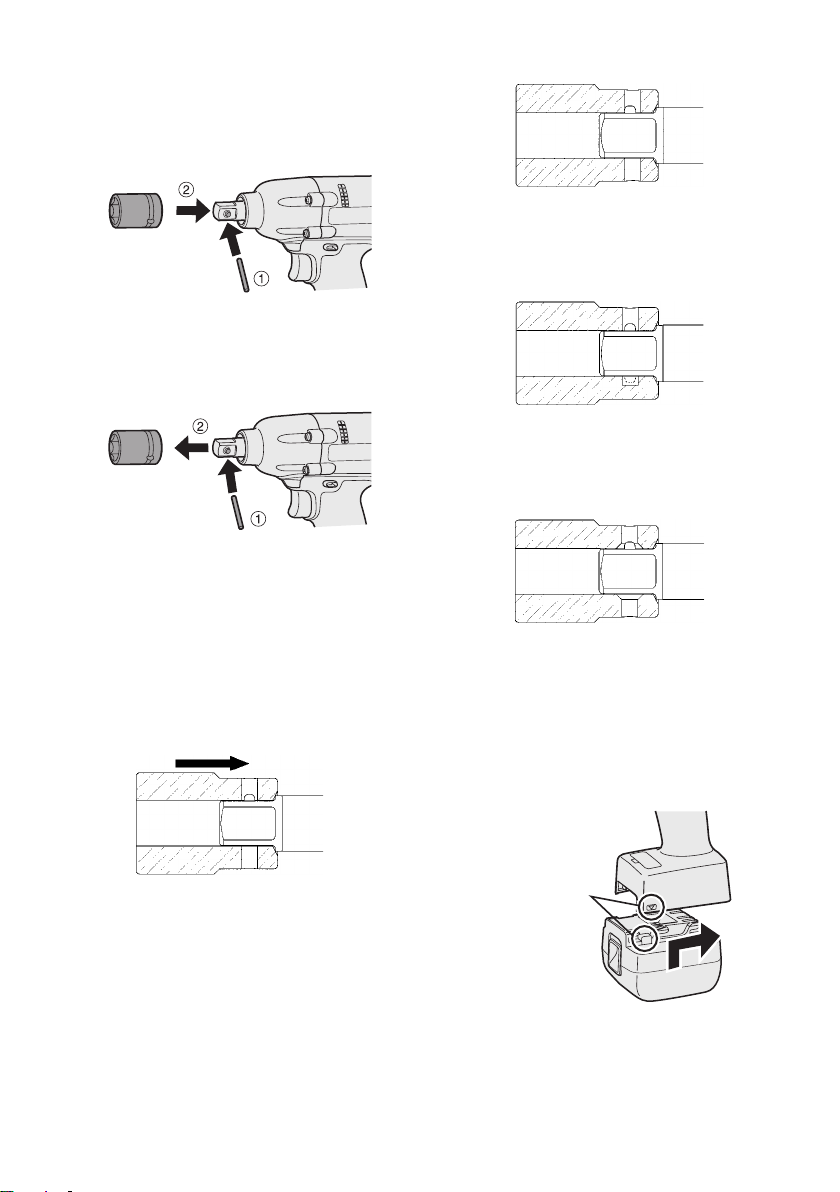
Attaching Socket (Pin-detent)
1 Depress the pin-detent on the square drive.
2 Attach the socket to square drive.
ake sure the socket is securely attached to
3 M
the square drive.
Removing Socket (Pin-detent)
1 Insert a small rod into the hole on the socket.
Depress the pin-detent, then detach the socket.
2
NOTE:
Keep the temperature of the tool above the
f
reezing point (0°C/32°F) when attaching
sockets to or removing them from the
square drive. Do not use excessive force
when attaching or removing sockets.
CAUTION:
•
When attaching a socket to the driver,
verify that the socket and pin-detent do
not interfere with one another.
T
he pin-detent will be subjected to
excessive force, possibly damaging it.
2 Sockets with a pin hole on one side
only
Y
ou may be unable to remove the
socket if it is attached in the wrong orientation.
3 Sockets whose pin holes have bev-
eled edges
T
he socket will not be held in place
with sufficient force, so that it may
come off during use.
Attaching or Removing Battery Pack
1. To connect the battery pack:
Line up the alignment marks and attach
the battery pack.
•
Slide the battery pack until it locks into
position.
Proper socket attachment
• Some sockets may not function well with
the driver due to their shape. Avoid use
of sockets such as the following:
1 Sockets
makes contact with the side of the
socket’s pin hole when the socket is
attached to the driver.
shaped so that the pin-detent
-
7 -
Alignment
marks
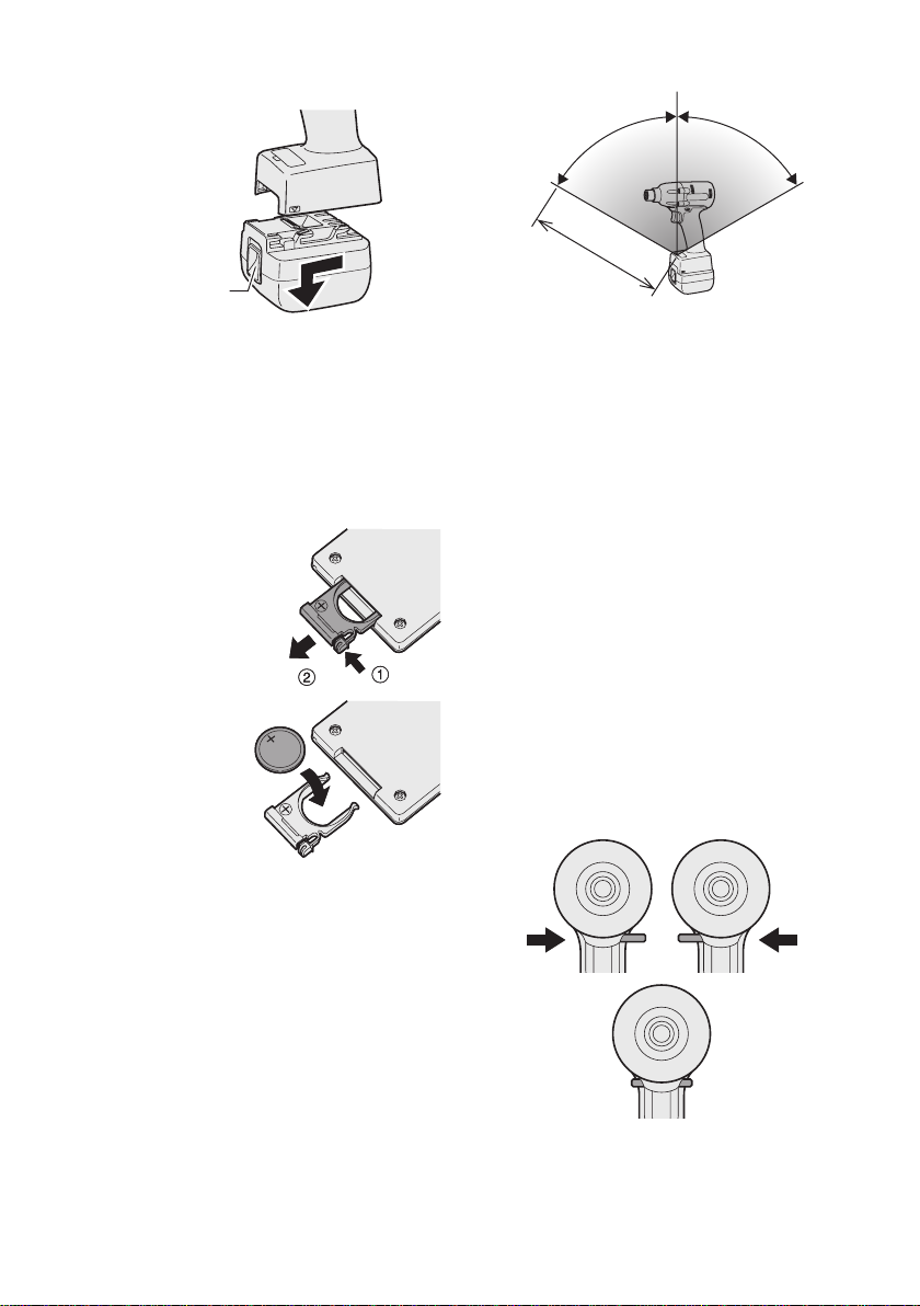
2. To remove the battery pack:
Approx. 50 cm
Vertically
A
p
p
r
o
x
.
6
0
°
A
p
p
r
o
x
.
6
0
°
Forward Reverse
Switch lock
Push up on the button from the front to release the battery pack.
Wireless remote control range
Button
V
. OPERATION
Before Using the Remote
Control (Available as an
optional accessory)
Insert the battery
1. Pull out the battery holder.
1 P
ush in on the fastener as indicated by
the arrow.
2 Pull out the holder
2. Insert the battery and
push the holder
back in.
NOTE:
•
If the tool does not respond to the wire-
less remote control even when the remote
control is operated close to the tool, the
attery (CR2025) is dead. Replace it with
b
a fresh battery.
•
The included battery is provided for sample
use and may not last as long as commercially available batteries.
.
The remote control should be operated within
approximately 50 cm and approximately 60°
vertically and horizontally of the perpendicular
relative to the infrared Assembly Qualier on
the tool.
Under the following circumstances, you may
•
not be able to operate the tool, even within
this range.
If there is an object between the remote
•
control’s transmitter and the tool’s Assembly Qualifier.
Use outdoors or in other environments
•
where the remote control Assembly Qualifier
is exposed to a strong light source, or when
the remote control transmitter or Assembly
Qualifier is dirty may cause the tool to fail to
respond, even when the remote control is
used within the operating range.
[Main Body]
Switch and Forward/Reverse
Lever Operation
-
CAUTION:
To prevent damage, do not operate
Forward/Reverse lever until the bit comes
to a complete stop.
8 -
Forward Rotation Switch
Operation
1. Push the lever for forward rotation.
2. Depress the trigger switch slightly to start
the tool slowly.
The speed increases with the amount of
3.
depression of the trigger for efficient tightening of screws. The brake operates and
the bit stops immediately when the trigger
is released.
4.
After use, set the lever to its center posi-
tion (switch lock).
Reverse Rotation Switch
Operation
1.
Push the lever for reverse rotation. Check
direction of rotation before use.
Depress the trigger switch slightly to start the
2
.
tool slowly.
3. After use, set the lever to its center position (switch lock).
CAUTION:
•
To eliminate excessive temperature
increase of the tool surface, do not
operate the tool continuously using two
or more battery packs. Tool needs cool
off time before switching to another
pack.
Tightening confirmation lamp
• The tightening confirmation lamp can be
used to check whether the torque control
function was activated.
the
CAUTION:
When the tool stops automatically after
•
the switch is released during impactmode tightening and then re-engaged
within 1 second, the red lamp will light up
to indicate the risk of excessive torque
application as a result of re-tightening.
NOTE
•
The tightening confirmation lamp will
not turn on under the following conditions:
•
When the torque clutch is set to “F”
• During reverse rotation operation
• The lamp turns off when the tool is in
operation.
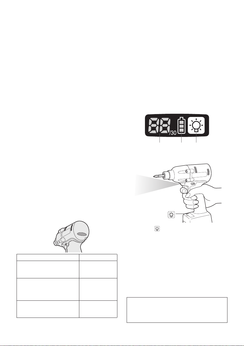
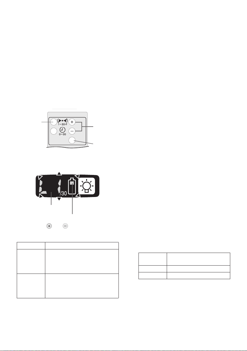
Control Panel
(1) (2) (3)
(1) LED light
Tool status Lamp display
Tightening complete
(with torque control
function operation)
Tightening not complete
•
• Tightening complete
with retightening within 1
second
The automatic stop
function has been
activated.
Green
(For approx.
seconds)
Red
(For approx.
seconds)
Red
(For approx. 5
minutes)
Pressing the button toggles the LED light on
and off.
The light illuminates with very low current, and
it does not adversely affect the performance
tool during use or its battery capacity.
the
CAUTION:
The built-in LED light is designed to illu-
2
2
-
9 -
•
minate the small work area temporarily.
•
Do not use it as a substitute for a regular
flashlight, since it does not have
enough brightness
This tool has the built-in LED light.
Caution: DO NOT STARE INTO BEAM.
Use of controls or adjustments or performance
of procedures other than those specied herein
may result in hazardous radiation exposure.
.
of
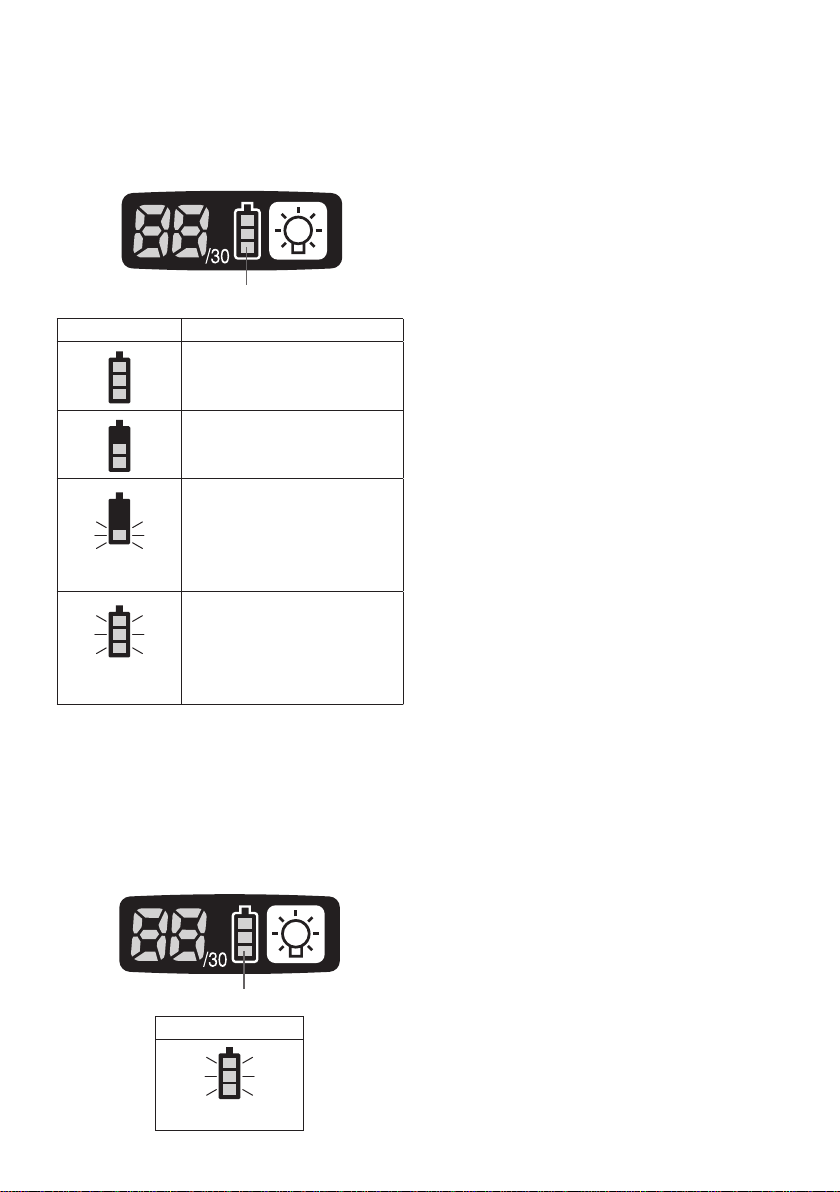
(2) The battery indication lamp
• Use the battery indication lamp to check
how much power is left in the battery.
Battery life varies slightly with ambient tem-
•
perature and battery characteristics. The
lamp is designed to provide a rough indication of remaining battery life.
Battery indication lamp
Indicator Battery status
Fully charged
Approx. 40% or less
remaining
Flashing
Approx. 20% or less
remaining (indicates need
to recharge battery)
Flashing
Flashing
The battery pack will need
to be charged soon.
No charge
The battery pack needs to
be charged.
(The tool’s automatic
power-off function will
activate at this stage.)
Automatic power-off function
• The automatic power-off function is designed
to prevent a loss of tightening torque due to
reduced battery voltage. Once it has been
activated, the tool will not operate until the
battery pack has been charged (or replaced
with a fresh unit), even if the trigger is
depressed.
Battery indication lamp
Indicator
Flashing
NOTE:
• All 3 bars on the battery indication lamp
will flash when the automatic power-off
function is activated.
When the battery indication lamp begins
•
flashing, the battery pack should be
charged (or replaced with a fresh unit)
immediately.
Be sure to fully charge the battery pack
•
in question after activation of the automatic power-off function. Failure to do
so may prevent the automatic power-off
function from being properly deactivated.
(3) The torque control function
• The torque control function calculates the
load from the motor’s rotational angle during
the hammer impact and determines that the
bolt has been properly seated when a preset load value is exceeded. Driving is then
automatically stopped after a preset number
of impacts have been delivered to the bolt.
CAUTION:
Always check the tool’s tightening
•
torque before use. Improper tool operation may result in excessive or inadequate tightening.
CAUTION:
•
Always operate the tool with the switch
fully engaged. The torque control function will not operate when the switch is
not sufficiently engaged, preventing the
tool from stopping automatically.
In work where a heavy load comes to
•
bear during tightening, the load may be
interpreted as the seating of the bolt,
preventing the bolt from being completely tightened.
Repeated tightening of the same bolt
•
may break the bolt or deform the material into which the bolt is being driven as
a result of excessive tightening.
The tightening torque value and preci-
•
sion vary with factors such as the material into which the bolt is being driven
and the condition of the socket being
used. Adjust the torque as necessary
for the work being performed. Bolt tightening torque varies due to the factors
described below.
1) Bolt
Bolt diameter: Tightening torque gener-
•
ally increases with bolt diameter.
•
Torque coefficient (indicated by the bolt
manufacturer), grade, length, etc.
-
10 -
2) Other
3…28
1F30 229
• Bit and socket condition: Material,
amount of play, etc.
•
Use of a universal joint or socket
adapter
•
User: Manner in which the tool is
applied to the bolt, strength with which
the tool is held, manner in which the
tool’s switch is engaged
Condition of object being tightened: Ma-
•
terial, seating surface finish
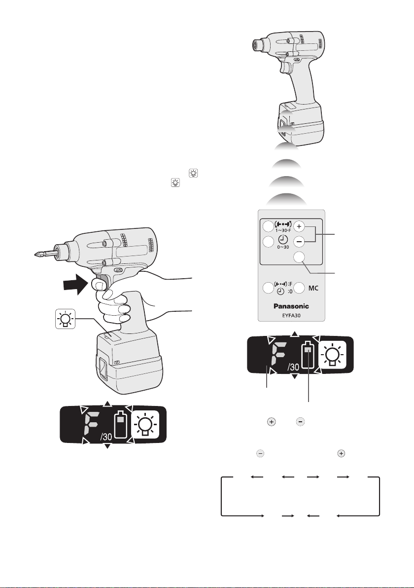
Setting the tool to configuration mode
1.
Turn off the control panel.
• If the control panel is on, remove and
then reinsert the battery pack.
. Engage the switch while pushing the
2
button and then release both the
ton and the switch.
After all the LED lamps have turned off,
•
the control panel will flash and change
to configuration mode.
Configuring the torque clutch setting
but-
(1)
(2)
NOTE:
• Tools ship from the factory set to “F”
mode (torque control function off).
•
The control panel will turn off if the tool
is not operated for a period of 5 minutes.
Display
Battery indication lamp
1. Press the and buttons to select the
clutch setting that is appropriate for the
work being performed.
-
11 -
As the button
is pressed
• “F” indicates that the torque control function is off.
As the button
is pressed
• You can select from 30 torque clutch
settings (1 to 30).
Use figures from the Tightening Torque
•
Chart to guide your selection of torque
clutch setting. (See the following tightening torque chart)
. Press the OK button to accept the select-
2
ed torque clutch setting.
•
The control panel will stop flashing and
light up.
CAUTION:
•
You must press the OK button in order
for the selected setting to take effect.
•
Be sure to verify the new value after
changing the setting. (See page 14.)
Setting the snug point detection level
(1)
1. Press the torque setting mode button.
• The snug point detection level setting
value will be displayed.
Display
Battery indication lamp
2. Press the and buttons to set the best
snug point detection level for the work
you’re performing.
Display Snug point detection level
L1
L
(Use for work characterized by
low loads before the snug point
(Use for work characterized by
2
high loads before the snug point
is reached.)
is reached.)
(2)
(3)
Low
High
3.
Press the OK button to accept the number
of torque stages and the snug point detection level.
The tool’s panel will flash and then light
•
up continuously.
CAUTION:
• Set the snug point detection level from
“L1.” Setting the snug point detection level
rom “L2” may result in cracking or defor-
f
mation of the target material.
f the tool stops before the snug point at
• I
snug point detection level “L1,” set the
nug point detection level to “L2.”
s
• Changing the snug point detection level
from “L1” to “L2” may increase the torque.
Set the number of torque stages again
after making this change.
• The setting will not be changed until
you press the OK button.
• After changing the setting, be sure to check
the new setting value. (See page 14.)
IMPORTANT INFORMATION:
• You can set the snug point detection
level and retightening prevention time at
the same time by changing the retightening prevention time (see page 13)
before pressing the OK button and then
pressing the OK button.
Pressing the torque setting mode but-
•
ton toggles the display between the
snug point detection level setting value
and the number of torque stages setting value.
The tool ships with the snug point
•
detection level set to “L1.”
When the number of torque stages has
•
been set as shown below, the snug
point detection level cannot be switched
from “L1” to “L
Model
EZFLA4 1 to 8
EZFLA5 1 to 3
2.”
Number of torque stages
setting
-
12 -
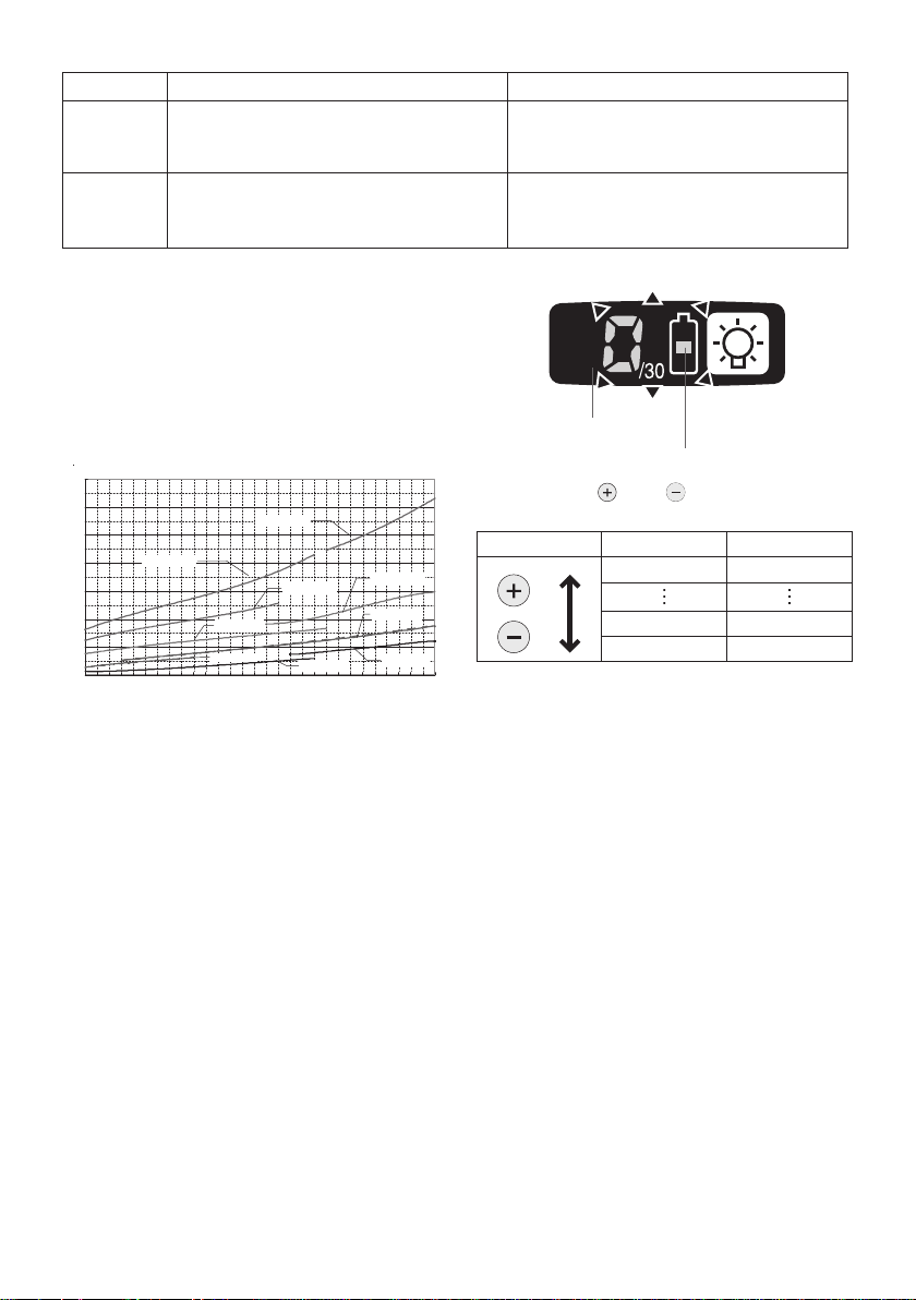
Snug point detection level guidelines
0
20
40
60
80
100
120
140
1 2 3 4 5 6 7 8 9 10 11 12 13 14 15 16 17 18 19 20 21 22 23 24 25 26 27 28 29 30
N
m
EYFLA4(M6)
EYFLA6(M8)
EYFLA4(M8)
EYFLA5(M8)
EYFLA6(M10)
EYFMA1(M10)
EYFMA1(M12)
EYFMA1(M14)
EYFLA5(M6)
Display Snug point detection level Applications (reference)
L1
L
(Use for work characterized by low loads
Low
before the snug point is reached.)
High
2
(Use for work characterized by high
loads before the snug point is reached.)
•
Tightening bolts in materials that are
easily cracked or deformed, etc.
•
Tightening bolts in materials with mis-
aligned holes, etc.
Tightening self-tapping screws, etc.
•
Tightening Torque Chart (for Reference Use)
The values illustrated on this chart were measured under the conditions described below
and are provided for reference purposes.
Actual tightening torque varies with ambient
conditions (the particular bolt being tightened,
hardware being used, method of holding the
bolt in place, etc.).
Display
Battery indication lamp
3. Press the and buttons to set the
desired time.
Buttons Display Seconds
30 3
1 0.1
0 Off
Measurement conditions
• Temperature: Room temperature (20°C/68°F)
Using the Interval Set
•
The interval set operates to prevent the tool
from operating after it automatically stops as
a result of the torque control function, even if
the switch is engaged.
1.
Set the tool to configuration mode.
(See page 11.)
2. Press the interval set button.
• The control panel will begin flashing.
Display: The number 0 ashes on and off.
Battery indication lamp: The middle bar
of the battery ashes on and off.
4.
Press the OK button to accept the select-
ed setting.
The control panel will stop flashing and
•
light up, and the torque clutch setting
will be displayed.
CAUTION:
Be sure to verify the new value after
•
changing the setting.
13 -
-
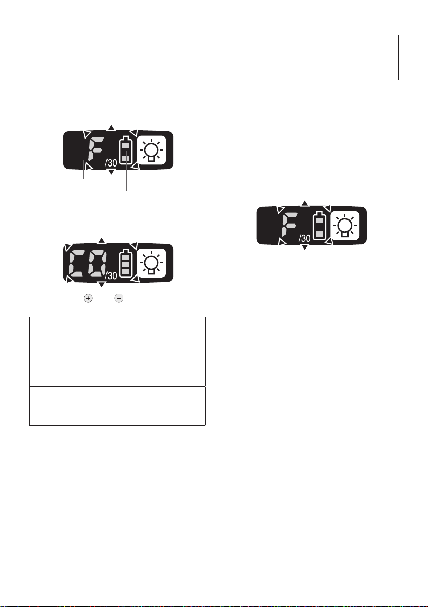
Radio signal range limitation function
on/off setting (EYFLA4AR, EYFLA5AR,
EYFLA5QR, EYFLA6PR)
1.
Set the tool to configuration mode.
(See page 11.)
2. Press the format button.
• The control panel will begin flashing.
Display: The letter “F” ashes on and off.
Battery indication lamp: The upper and
lower bars of the battery ash on and off.
Display
Battery indication lamp
3. Press the format button again.
• Radio signal range limitation function
on/off setting value will be displayed.
4. Press the and buttons to set radio
signal range limitation function on/off.
Display
Factory settings
Radio signal
range limitation
function mode
Tool is operational in the
C0 OFF
C1 ON
• Radio signal range limitation function
setting: C0 (OFF)
NOTE:
•
For more information about how to register
the tool and assembly qualifier, see the
assembly qualifier instruction manual.
absence of communications with the Assembly
Qualier.
Tool is not operational
in the absence of communications with the As-
sembly Qualier.
Status
Initializing All Settings
Factory settings
• Torque clutch setting: “F” (torque control function off)
•
Interval setting: 0 (off)
• This section explains how to revert all tool
settings to their default values at the time of
shipment from the factory.
•
The error display will be turned off.
1. Set the tool to configuration mode.
(See page 11.)
2. Press the format button.
• The control panel will begin flashing.
Display: The letter “F” ashes on and off.
Battery indication lamp: The upper and
lower bars of the battery ash on and off.
Display
Battery indication lamp
3. Press the OK button to accept the select-
ed setting.
The control panel will stop flashing and
•
light up.
Checking Tool Settings
•
This section describes how to have the
tool display current settings for approximately 3 seconds when the tool is
stopped.
You cannot check tool settings when the
•
control panel is turned off. First, engage
the switch briefly to reactivate the display.
Checking the sung point detection setting
Press the torque set button.
1.
• Control panel display
Display: The torque set lights up.
Battery indication lamp: The upper and mid-
dle bars of the battery ash on and off.
Checking the interval
1. Press the interval set button.
• Control panel display
Display: The interval set lights up.
Battery indication lamp: The middle bar
of the battery ashes on and off.
-
14 -
Checking tool circuits
1. Press the torque level button.
• Control panel display
Display: The torque set display lights up.
Battery indication lamp: The middle and
lower bars of the battery ash on and off.
Display Tool circuit
H6 EYFLA4
H7 EYFLA5
H8 EYFLA6
H9 EYFMA1
NOTE:
•
If you engage the switch while a setting
is being displayed, the control panel will
revert to the torque clutch setting display.
CAUTION:
The torque set display is not intended
•
to be used to identify the type of drive
component parts (hammer, etc.) used
in a particular tool.
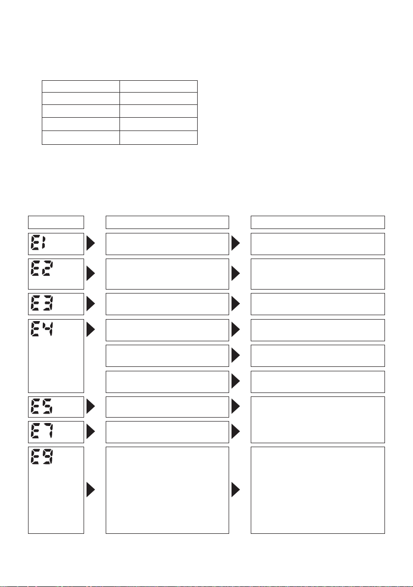
Error Display
In the event of a tool or battery pack malfunction, the control panel will display an error message.
Please check the tool or battery pack as described in the following chart before having them
serviced.
Display Likely cause Corrective action
Setting error Re-initialize the tool using the
The battery pack is too hot. Stop work and allow the battery
The tool is too hot to operate. Stop work and allow the tool to
The contacts that connect the
battery pack and tool are dirty.
The battery pack has not been
properly inserted into the tool.
The pins on either the tool or
battery pack have worn down.
Motor failure, etc. Stop using the tool immediately.
Tool circuit malfunction, failure,
etc.
The tool is unable to communicate with the Assembly Quali-
er while the radio signal range
limitation function is on.
remote control. (See page 14.)
pack to cool before resuming use
of the tool.
cool before resuming use.
Remove any dirt.
Insert the battery pack rmly into
the tool.
Replace the battery pack.
• Verify that the tool has been
properly registered to the Assembly Qualifier.
Verify that the Assembly Qualifi-
•
er’s group setting has been configured correctly.
Improve the reception state, for
•
example by moving the Assembly Qualifier closer to the tool.
-
15 -

-
16 -
[Battery Pack]
For Appropriate Use of Bat-
tery Pack
Li-ion Battery Pack
• For optimum battery life, store the Li-ion battery pack following use without charging it.
• When charging the battery pack, confirm
that the terminals on the battery charger
are free of foreign substances such as dust
and water etc. Clean the terminals before
charging the battery pack if any foreign substances are found on the terminals.
The life of the battery pack terminals may be
affected by foreign substances such as dust
and water etc. during operation.
• When battery pack is not in use, keep it
away from other metal objects like: paper
clips, coins, keys, nails, screws, or other
small metal objects that can make a connection from one terminal to another.
Shorting the battery terminals together may
cause sparks, burns or a fire.
• When operating the battery pack, make sure
the work place is well ventilated.
• When the battery pack is removed from the
main body of the tool, replace the battery
pack cover immediately in order to prevent
dust or dirt from contaminating the battery
terminals and causing a short circuit.
Battery Pack Life
The rechargeable batteries have a limited life.
If the operation time becomes extremely short
after recharging, replace the battery pack with
a new one.
Battery Recycling
ATTENTION:
A Li-ion battery that is recyclable powers
the product you have purchased.
Please call 1-800-8-BATTERY for information on how to recycle this battery.
[Battery Charger]
Charging
Read the operating manual for Panasonic battery charger for the battery pack before charging.
Before charging the battery
Charge the battery at a temperature of 5°C
(41°F) to 40°C (104°F).
The battery pack cannot be charged at a temperature of less than 5°C (41°F). If the temperature of the battery pack is less than 5°C
(41°F), rst remove the battery pack from
the charger and allow it to sit for an hour in a
location where the temperature is 5°C (41°F) or
warmer. Then charge the battery pack again.
VI.
MAINTENANCE
Use only a dry, soft cloth for wiping the unit.
Do not use a damp cloth, thinner, benzine, or
other volatile solvents for cleaning.

VII
. ACCESSORIES
Charger
• EY0L80
• EY0L81
Battery pack
•
EYFB30
• EYFB40
Remote control
•
EYFA30
Protector for tool
EYFA01-A (Blue)
•
• EYFA01-Y (Yellow)
• EYFA01-H (Gray)
• EYFA01-G (Green)
Protector for battery
•
EYFA02-H
• EYFA04-H
Assembly Qualier
•
EYFRZ01
• EYFR02
Federal Communications Commission Interference
Statement
This equipment has been tested and found to comply with the limits for a Class B digital device,
pursuant to part 15 of the FCC Rules. These limits are designed to provide reasonable protection
against harmful interference in a residential installation. This equipment generates, uses and can
radiate radio frequency energy and, if not installed and used in accordance with the instructions,
may cause harmful interference to radio communications. However, there is no guarantee that
interference will not occur in a particular installation. If this equipment does cause harmful interference to radio or television reception, which can be determined by turning the equipment off
and on, the user is encouraged to try to correct the interference by one or more of the following
measures:
Reorient or relocate the receiving antenna.
•
•
Increase the separation between the equipment and receiver.
•
Connect the equipment into an outlet on a circuit different from that to which the receiver is
connected.
Consult the dealer or an experienced radio/TV technician for help.
•
FCC Caution: To assume continued compliance, install and use in accordance with provided
instructions. Use only the battery pack specied in the instructions. Any changes or modications
not expressly approved by the party responsible for compliance could void the user’s authority to
operate this equipment.
FCC ID: O4O-EYFLA IC : 8507A-EYFLA
The enclosed device complies with Part 15 of the FCC Rules. Operation is subject to the following
two conditions: (i.) this device may not cause harmful interference and (ii.) this device must accept
any interference received, including interference that may cause undesired operation.
This Class B digital apparatus complies with Canadian ICES-003.
Panasonic Electric Works Power Tools Co., Ltd.
33, Okamachi, Hikone, Shiga, Japan
17 -
-
 Loading...