

Panasonic EYFLA, EYFMA, EY9810FLA49 Operation Manual
Operating Instructions
Instructions d’utilisation
Manual de instrucciones
Cordless Mechanical Pulse Driver / Cordless Mechanical Pulse Wrench
Visseuse à impulsions mécaniques sans fil / Clé de serrage à impulsions mécaniques sans fil
Atornillador de impulso mecánico inalámbrico / Llave de impulso mecánico inalámbrica
Model No : EYFLA4A / EYFLA4AR
EYFLA5A / EYFLA5AR
EYFLA5P / EYFLA5PR
EYFLA5Q / EYFLA5QR
EYFLA6J / EYFLA6JR
EYFLA6P / EYFLA6PR
EYFLA7A / EYFLA7AR
EYFLA8A / EYFLA8AR
EYFLA8C / EYFLA8CR
EYFLA8P / EYFLA8PR
EYFLA9C / EYFLA9CR
EYFLA9P / EYFLA9PR
EYFMA1J / EYFMA1JR
EYFMA1P / EYFMA1PR
EYFMA2C / EYFMA2CR
EYFMA2P / EYFMA2PR
EYFLA4A EYFLA9C
IMPORTANT
This manual contains safety information. Read manual completely before first using this product and save this
manual for future use.
IMPORTANT
Ce mode d’emploi contient des informations sur la sécurité. Lisez-le en entier avant d’utiliser le produit et
conservez-le pour référence.
IMPORTANTE
Este manual contiene información de seguridad. Lea completamente este manual antes de utilizar por primera
vez este producto, y guárdelo para poder consultarlo en el futuro.
Index / Index / Indice
CD
English: Page 10
Français: Page 30
Español: Página 53
FUNCTIONAL DESCRIPTION
DESCRIPTION DES FONCTIONS
DESCRIPCIÓN FUNCIONAL
EYFLA4A / EYFLA4AR
EYFLA5A / EYFLA5AR
EYFLA7A / EYFLA7AR
EYFLA8A / EYFLA8AR
EYFLA5Q / EYFLA5QR
EYFLA6J / EYFLA6JR
EYFMA1J / EYFMA1JR
EYFLA5P / EYFLA5PR
EYFLA6P / EYFLA6PR
EYFLA9P / EYFLA9PR
EYFMA1P / EYFMA1PR
EYFMA2P / EYFMA2PR
(A)-1
(A)-2 (A)-3
(A)
EYFLA8C / EYFLA8CR
EYFLA9C / EYFLA9CR
EYFMA2C / EYFMA2CR
(I)
(H)
(G)
(J)(K)(L)
(F)
(E)
Other than
EYFLA7 / EYFLA8
EYFLA9 / EYFMA2
Autre que
EYFLA7 / EYFLA8
EYFLA9 / EYFMA2
Diferente de
EYFLA7 / EYFLA8
EYFLA9 / EYFMA2
Remote control and battery are not included.
La télécommande et la batterie ne sont pas incluses.
El control remoto y la batería no están incluídos.
(V)
(U)
(T)
(S)
(R)
(D)
(M)
A
B
EYFA31
EYFA31
(W)
(B)
[Fig.17]
(C)
(N)
(O)
(P)
(Q)
-
2 -

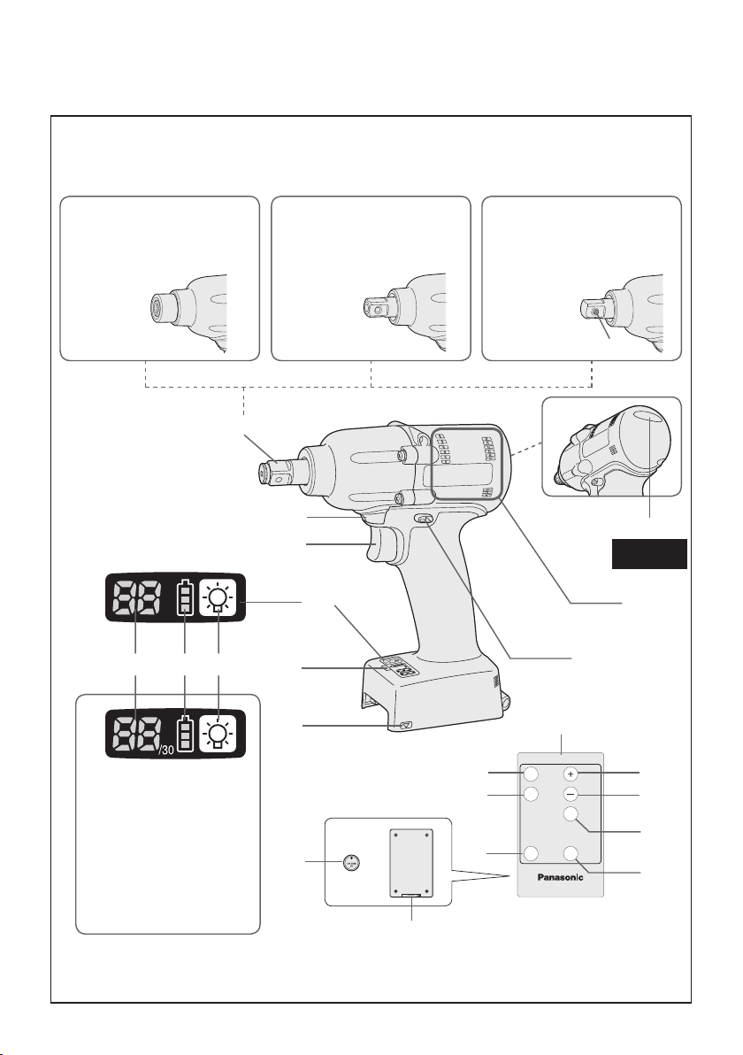
Square drive (retainer ring and pin)
Entraînement carré (anneau de retenue et goupille)
(A)
Excitador cuadrado (anillo retenedor y pasador)
6.35 mm (1/4”) hex quick connect chuck
Mandrin de connexion rapide hexagonal de 6,35 mm (1/4”)
(A-1)
Mandril de conexión rápida hexagonal de 6,35 mm (1/4”)
Square drive (pin type)
Entraînement carré (type à goujon)
(A-2)
Excitador cuadrado (tipo pasador)
Square drive (pin-detent type)
Entraînement carré (type à goupille d’arrêt)
(A-3)
Excitador cuadrado (tipo pasador retenedor)
Tightening conrmation lamp
Témoin de conrmation de serrage
(B)
Lámpara de conrmación de apriete
Vent holes
(C)
Trous d'aération
Agujeros de ventilación
Forward/Reverse lever
Levier d’inversion marche avant/marche arrière
(D)
Palanca de avance/marcha atrás
Alignment marks
(E)
Marques d’alignement
Marcas de alineación
Remote control receiver
Récepteur de la télécommande
(F)
Receptor de control remoto
Control panel
Panneau de commande
(G)
Panel de control
Variable speed control trigger
Gâchette de commande de vitesse
(H)
Disparador del control de velocidad variable
LED light
Lumière DEL
(I)
Luz indicadora
LED light on/off button
Bouton Marche/Arrêt de la lumière DEL
(J)
Botón ON/OFF de luz LED
Battery indication lamp
Témoin indicateur de la batterie
(K)
Lámpara de indicadora de la batería
Display
Afchage
(L)
Visor
Remote control
(M)
Télécommande
Control remoto
+ button
(N)
Bouton +
Botón +
− button
(O)
Bouton −
Botón −
OK button
(P)
Bouton OK
Botón OK (correcto)
D button
(Q)
Bouton D
Botón D
C button
(R)
Bouton C
Botón C
B button
(S)
Bouton B
Botón B
A button
(T)
Bouton A
Botón A
Holder
(U)
Support
Retenedor
Battery
(V)
Batterie
Batería
Pin-detent
(W)
Goupille d'arrêt
Pasador retenedor
-
3 -
Illustrations / Illustrations / Ilustraciones
[Fig.1]
rubber ring
anneau en
caoutchouc
anillo de cauch
[Fig.2]
[Fig.3]
o
pin
goupille
pasador
[Fig.6]
groove
rainure
ranura
Proper socket attachment
Fixation correcte de la douille
Montaje de cubo apropiado
[Fig.7]
[Fig.8]
[Fig.9]
[Fig.4]
[Fig.5]
-
[Fig.10]
Alignment
marks
Marques
d’alignement
Marcas de
alineación
[Fig.11]
Button
Bouton
Botón
4 -
[Fig.12]
[Fig.16]
[Fig.13]
[Fig.14]
Vertically
Verticalement
Verticalmente
Forward
Rotation en
sens normal
Avance
Verrouillage de commutateur
[Fig.17]
[Fig.18]
Reverse
Rotation en
sens inverse
Marcha
atrás
Switch lock
Bloqueo del interruptor
EYFLA9 / EYFMA2
Approx. 50 cm
Environ 50 cm
Aprox. 50 cm
[Fig.15]
Approx. 60°
Environ 60°
Aprox. 60°
-
5 -
(2) (1)
EYFLA9 / EYFMA2
(2) (1)
[Fig.19]
CD
[Fig.20]
[Fig.21]
Display
Afchage
Visor
Battery indication lamp
Témoin indicateur de la batterie
Lámpara de indicadora de la batería
EYFLA9 / EYFMA2
[Fig.22]
Tightening torque
Couple de serrage
Par de torsión de apriete
Niveau de réglage du couple de serrage
A
(1)
B
(2)
EYFA31
EYFLA9 / EYFMA2
EYFMA1(M14)
EYFMA1(M12)
EYFMA1(M10)
EYFLA5(M6)
EYFLA4(M6)
Torque setting level
Nivel de ajuste de par de torsión
EYFLA6(M10)
EYFLA6(M8)
EYFLA5(M8)
EYFLA4(M8)
-
6 -
[Fig.23]
[Fig.24]
Tightening torque
Couple de serrage
Par de torsión de apriete
Niveau de réglage du couple de serrage
[Fig.26]
Torque setting
Réglage du couple
de serrage
Ajuste de par de
torsión
Torque setting level
Nivel de ajuste de par de torsión
Torque
Couple de serrage
Par de torsión
L7
(1)
A
B
[Fig.25]
EYFLA9 / EYFMA2
Tightening completed
Serrage terminé (s’arrête automatiquement)
Apriete terminado (Se detiene automáticamente)
(Stops automatically)
(2)
(3)
Snug point
detection level
Niveau de
détection du
point de
préserrage
Nivel de
detección del
punto de apriete
exacto
L6
L5
L4
L3
Load generated halfway
Charge générée à mi-chemin
L2
Carga generada a la mitad
L1
Load generated halfway
Charge générée à mi-chemin
Carga generada a la mitad
-
7 -
Snug point
Point de
préserrage
Punto de
apriete exacto
Impact Monitoring
Mode
Mode de surveillance
de l’impact
Modo de monitoreo
de impacto
Tightening time
Durée du serrage
Tiempo de apriete
[Fig.27]
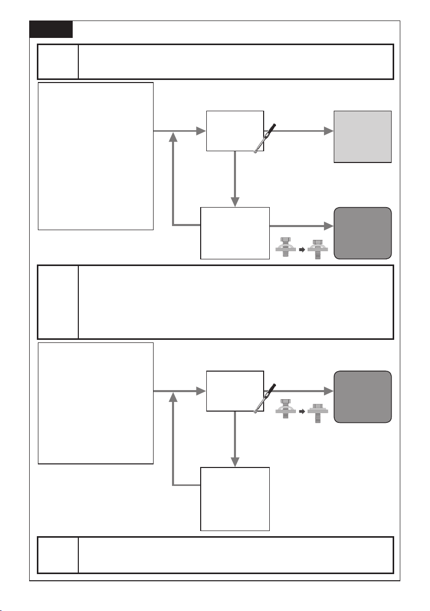
How to set / Comment régler ? / Cómo ajustar
[Step 1]
Étape 1
[
[Paso 1]
Select Torque Setting Stage (1-40)
]
Sélectionnez l’étape de réglage du couple de serrage (1-40)
Seleccione Etapa de ajuste de par de torsión (1-40)
Torque Setting Stage:
Select referring to index chart
[Fig. 23]
Snug Tight Detection setting: L1
Étape de réglage du couple de
serrage :
Sélectionnez se référer au
tableau d’annexe [Fig. 23]
Réglages de la détection de
préserrage serré : L1
Etapa de ajuste de par de torsión:
Seleccione consultando el
cuadro de índice [Fig. 23]
Ajuste de detección de punto de
apriete exacto: L1
[Step 2]
Étape 2
[
[Paso 2]
Torque Setting Stage:
* Select referring to index chart
Snug Tight Detection setting:
Change from L1 to L2
Étape de réglage du couple de
serrage :
* Sélectionnez se référer au
tableau d’annexe
Réglages de la détection de préserrage
serré : Modification de L1 à L2
Etapa de ajuste de par de torsión:
* Seleccione consultando el
cuadro de índice
Ajuste de detección de punto de
apriete exacto: Cambie de L1 a L2
* Please reset Torque Setting Stage if it’s
increased in Step1.
* Veuillez réinitialiser l’étape de réglage
du couple de serrage si elle a été
augmentée à l’étape 1.
* Vuelva a ajustar la Etapa de ajuste de par
de torsión si se aumentó en el Paso 1.
Select Flush Detection Level (L1-L7 / Use only when final torque can’t be increased by Torque
Setting Stage change)
* Increase Flush Detection Level one by one. There is a risk of over torque when Flush Detection Level is increased.
Sélectionnez le niveau de détection de l’encastrement (L1-L7 / à utiliser uniquement quand le couple de
]
serrage final ne peut pas être augmenté par la modification de l’étape de réglage du couple de serrage)
* Augmente le niveau de détection d’encastrement un par un. Il existe un risque de trop fort couple de serrage lorsque le
niveau de détection d’encastrement est augmenté.
Seleccione Nivel de detección de nivel (L1-L7 / Use sólo cuando el par de torsión final se puede
aumentar mediante el cambio de la Etapa de ajuste de par de torsión)
*
Aumente el nivel de detección de nivel uno a uno. Existe la posibilidad de que se apriete demasiado cuando se aumenta el nivel de detección de nivel.
Trial fastening
Essai de
fixation
Apriete de
prueba
Trial fastening
Essai de
fixation
Apriete de
prueba
Final torque meets target torque
Le couple de serrage final correspond au couple de serrage prévu
Par de torsión final cumple con el par de apriete objetivo
Check torque
Vérifiez le couple
de serrage
Verifique par
de torsión
Even though changing Torque Setting
Not OK
Pas OK
No OK
Modifiez l’étape de réglage
du couple de serrage
ajuste de par de torsión
Vérifiez le couple
Not OK
Pas OK
No OK
Modifiez les réglages de la
détection de préserrage serré
detección de punto de
Stage, final torque can’t be increased.
(Fastener doesn’t seat correctly)
Malgré la modification de l’étape de réglage du couple de serrage,
le couple de serrage final ne peut pas être augmenté.
(L’attache n’est pas fixée correctement)
A pesar de cambiar la Etapa de ajuste de par de torsión, el par de
torsión final no se puede aumentar.
(Seguro no se asienta correctamente)
Change Torque
Setting Stage
Cambie Etapa de
Final torque is above lower tolerance limit
Le couple de serrage final dépasse la limite inférieure de tolérance
Par de torsión final está encima del límite de tolerancia inferior
Check torque
de serrage
Verifique par
de torsión
Final torque can’t be increased.
(Fastener doesn’t seat correctly)
Le couple de serrage final ne peut pas être augmenté.
(L’attache n’est pas fixée correctement)
El par de torsión final no se puede aumentar.
(Seguro no se asienta correctamente)
Change Snug Tight
Detection setting
L2→L3~L7
L2→L3~L7
Cambie el ajuste de
apriete exacto
L2→L3~L7
OK / OK / OK
Not OK
OK / OK / OK
Flush!
Setting
complete
Réglage
terminé
Ajuste
completo
Move to Step 2
Passez à l’étape 2
Vaya al Paso 2
Move to Step 3
Passez à l’étape 3
Vaya al Paso 3
[Step 3]
Étape 3
[
[Paso 3]
Fine-tune Torque Setting Stage to meet target torque and complete setting
]
Affinez l’étape de réglage du couple de serrage afin d’atteindre le couple de serrage prévu et de terminer les réglages
Haga el ajuste fino de Etapa de ajuste de par de torsión para cumplir con el par de torsión objetivo y completar el ajuste.
-
8 -
[Fig.28]
EYFLA9 / EYFMA2
[Fig.32]
[Fig.29]
EYFLA4AR, EYFLA5AR, EYFLA5PR,
EYFLA5QR, EYFLA6JR, EYFLA6PR,
EYFLA7AR, EYFLA8AR, EYFLA8CR,
EYFLA8PR, EYFLA9CR, EYFLA9PR
EYFMA1JR, EYFMA1PR, EYFMA2CR,
EYFMA2PR
[Fig.30]
[Fig.33]
EYFLA9 / EYFMA2
[Fig.34]
EYFLA9 / EYFMA2
[Fig.31]
-
9 -
[Fig.35]

6)
EN EN
I
.
GENERAL SAFETY
RULES
If operating a power tool in a damp
location is unavoidable, use a residual
current device (RCD) protected supply.
Use of RCD reduces the risk of electrical
shock.
WARNING! Read all instructions
Failure to follow all instructions listed
below may result in electric shock, fire
and/or serious injury. The term “power
tool” in all of the warnings listed below
refers to your mains operated (corded)
power tool and battery operated
(cordless) power tool.
SAVE THESE INSTRUCTIONS
Work Area Safety
1) Keep work area clean and well lit.
Cluttered or dark areas invite accidents.
2)
Do not operate power tools in explosive
atmospheres, such as in the presence
of flammable liquids, gases or dust.
Power tools create sparks which may
ignite the dust or fumes.
3) Keep children and bystanders away
while operating a power tool.
Distractions can cause you to lose control.
Electrical Safety
1) Power tool plugs must match the
outlet. Never modify the plug in any
way. Do not use any adapter plugs
with earthed (grounded) power tools.
Unmodified plugs and matching outlets
will reduce risk of electric shock.
2) Avoid body contact with earthed or
grounded surfaces such as pipes,
radiators, ranges and refrigerators.
There is an increased risk of electric shock
if your body is earthed or grounded.
3) Do not expose power tools to rain or
wet conditions.
Water entering a power tool will increase
the risk of electric shock.
4) Do not abuse the cord. Never use
the cord for carrying, pulling or
unplugging the power tool. Keep
cord away from heat, oil, sharp edges
or moving parts.
Damaged or entangled cords increase
the risk of electric shock.
5)
When operating a power tool outdoors,
use an extension cord suitable for
outdoor use.
Use of a cord suitable for outdoor use
reduces the risk of electric shock.
Personal Safety
1)
Stay alert, watch what you are doing
and use common sense when operating
a power tool. Do not use a power tool
while you are tired or under the influence
of drugs, alcohol or medication.
A moment of inattention while operating
power tools may result in personal injury.
2) Use safety equipment. Always wear
eye protection.
Safety equipment such as dust mask,
non-skid safety shoes, hard hat, or
hearing protection used for appropriate
conditions will reduce personal injuries.
3) Avoid accidental starting. Ensure the
switch is in the off position before
plugging in.
Carrying power tools with your finger on
the switch or plugging in the power tools
that have the switch on invites accidents.
4) Remove any adjusting key or wrench
before turning the power tool on.
A wrench or a key left attached to a
rotating part of the power tool may result
in personal injury.
5) Do not overreach. Keep proper
footing and balance at all times.
This enables better control of the power
tool in unexpected situations.
6) Dress properly. Do not wear loose
clothing or jewellery. Keep your
hair, clothing and gloves away from
moving parts.
Loose clothes, jewellery or long hair can
be caught in moving parts.
7) If devices are provided for the
connection of dust extraction and
collection facilities, ensure these are
connected and properly used.
Use of these devices can reduce dust
related hazards.
Power Tool Use and Care
1)
Do not force the power tool. Use the
correct power tool for your application.
The correct power tool will do the job
better and safer at the rate for which it
was designed.
-
10 -

2) Do not use the power tool if the
switch does not turn it on and off.
Any power tool that cannot be controlled
with the switch is dangerous and must
be repaired.
3) Disconnect the plug from the power
source and/or the battery pack from
the power tool before making any
adjustments, changing accessories,
or storing power tools.
Such preventive safety measures
reduce the risk of starting the power tool
accidentally.
4)
Store idle power tools out of the reach
of children and do not allow persons
unfamiliar with the power tool or these
instructions to operate the power tool.
Power tools are dangerous in the hands
of untrained users.
5) Maintain power tools. Check for
misalignment or binding of moving
parts, breakage of parts and any other
condition that may affect the power
tools operation. If damaged, have the
power tool repaired before use.
Many accidents are caused by poorly
maintained power tools.
6) Keep cutting tools sharp and clean.
Properly maintained cutting tools with
sharp cutting edges are less likely to
bind and are easier to control.
7) Use the power tool, accessories
and tool bits etc. in accordance with
these instructions and in the manner
intended for the particular type of
power tool, taking into account the
working conditions and the work to
be performed.
Use of the power tool for operations
different from those intended could
result in a hazardous situation.
8) Hold power tool by insulated gripping
surfaces, when performing an
operation where the fastener may
contact hidden wiring.
Fasteners contacting a “live” wire may
make exposed metal parts of the power
tool “live” and could give the operator an
electric shock.
Battery Tool Use and Care
1) Ensure the switch is in the off position
before inserting battery pack.
Inserting battery pack into power tools
that have the switch on invites accidents.
2) Recharge only with the charger
specified by the manufacturer.
A charger that is suitable for one type
of battery pack may create a risk of fire
when used with another battery pack.
3) Use power tools only with specifically
designated battery packs.
Use of any other battery packs may
create a risk of injury and fire.
4)
When battery pack is not in use, keep it
away from other metal objects like paper
clips, coins, keys, nails, screws, or other
small metal objects that can make a
connection from one terminal to another.
Shorting the battery terminals together
may cause burns, or a fire.
5) Under abusive conditions, liquid may
be ejected from battery; avoid contact.
If contact accidentally occurs, flush
with water. If liquid contacts eyes,
additionally seek medical help.
Liquid ejected from the battery may
cause irritation or burns.
Service
1) Have your power tool serviced by a
qualified repair person using only
identical replacement parts.
This will ensure that the safety of power
tool is maintained.
II
. INTENDED USE
This tool is a Cordless Mechanical Pulse Driver /
Wrench and can be used to tighten bolts, nuts,
and screws. Additionally, it provides a torque
control function that automatically stops tool
operation when a preset load is reached to deliver consistent tightening torque.
Additionally, a separately available Assembly
Qualier can provide wireless monitoring to
determine whether tightening has been completed properly.
IMPROPER USE
The use of the tool other than INTENDED USE
is dangerous and must be avoided.
The tool must not be used for the purposes
such as the following;
• to mix paint or building materials,
• polishing, grinding, sharpening, engraving.
-
11 -

RESIDUAL RISK
EN EN
Some residual risks remains even with proper
use of the tool such as the following;
• contact with the rotating bit
• contact with the sharp edges of material or
something.
III
.
ADDITIONAL SAFETY
RULES
1) If the bit becomes jammed, immedi-
ately turn the trigger switch off to prevent an overload, which can damage the battery pack or motor. Use
reverse motion to loosen jammed
bits.
2) Do NOT operate the Forward/
Reverse lever when the trigger switch
is on. The battery will discharge rapidly and damage to the unit may
occur.
3) During charging, the charger may
become slightly warm. This is normal.
Do NOT charge the battery for a long
period.
4) Do not strain the tool by holding the
speed control trigger halfway (speed
control mode) so that the motor
stops.
5) To prevent injury during use, hold
the tool steady at all times and avoid
waving it around.
6) Make certain that there are no hidden
gas or water pipes, or electrical wires
in the area where you will be working. Coming into contact with hidden
pipes or wires could result in electric
shock, or water or gas leaks.
7) Make sure to hold the object you are
working on steady.
8) Check for damaged parts.
• Check thoroughly for damage to
the protective cover and other parts
before operating.
• Check to make sure the tool and all
of its functions are working properly.
• Check the adjustment of all movable parts, and check all fixed parts
to make sure they are fitted properly
and free of damage. Check all parts
of the tool for abnormal function.
9) When attempting to repair the protective cover or other parts, please follow
the instructions in the user manual. In
cases where there are no instructions
in the manual, please take it back to
the store to have it repaired.
10) If the tool gets exceptionally hot during use, please take it in for service
and repair.
11) To avoid potential injury, keep face
and hands away from the drill bit and
any shavings.
12) Do not wear gloves when operating
the tool, as they may get caught by
the drill, leading to injury.
13) Battery terminals, screw shavings,
and tool accessories such as drill
bits will be very hot immediately after
operation. Do not touch them as
there is a risk of burning yourself.
-
12 -
WARNING
• Do not use other than the Panasonic battery packs that are designed for use with
this rechargeable tool.
• Panasonic is not responsible for any damage or accident caused by the use of
recycled or counterfeit battery pack.
• Do not dispose of the battery pack in a
fire, or expose it to excessive heat.
• Do not allow metal objects to touch the
battery pack terminals.
• Do not carry or store the battery pack
in the same container as nails or similar
metal objects.
• Do not charge the battery pack in a
high-temperature location, such as next
to a fire or in direct sunlight. Otherwise,
the battery may overheat, catch fire, or
explode.
• After removing the battery pack from the
tool or the charger, always reattach the
pack cover. Otherwise, the battery contacts could be shorted, leading to a risk
of fire.
• When the Battery Pack Has Deteriorated,
Replace It with a New One. Continued
use of a damaged battery pack may result
in heat generation, ignition or battery rupture.
• To prevent leakage, overheating, smoke
generation, fire, and rupturing from occurring, follow these instructions when handling our rechargeable power tools (tool
main body/battery pack/charger).
- Do not allow material cuttings or dust to
fall onto the battery pack.
- When storing, remove any material cuttings and dust from the battery pack,
and place the battery pack separately
from metal objects (screws, nails, etc.)
when storing in the tool case.
• Do not handle the rechargeable power
tools in the following way.
(There is a hazard of smoke generation,
fire, and rupturing)
- Use or leave in places exposed to rain
or moisture
- Use submerging in water
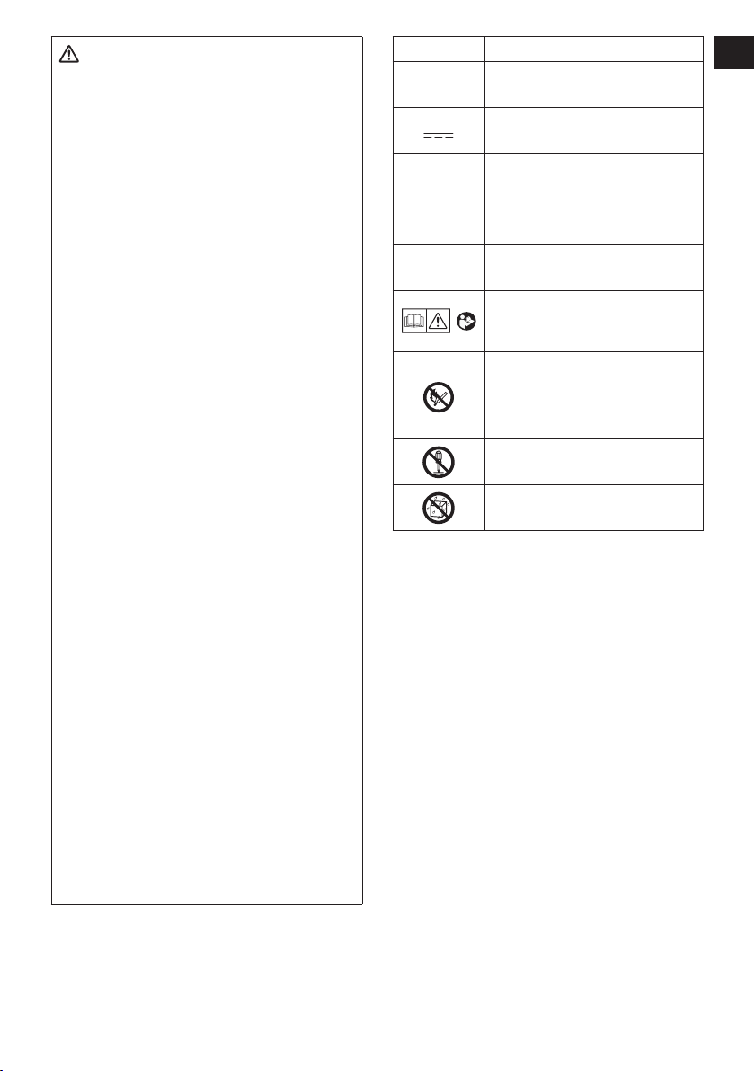
Symbol Meaning
V
n
0
Revolutions or reciprocations
-1
… min
Ah
IV
. ASSEMBLY
Electrical capacity of battery
injury, user must read and
understand instruction manual.
Do not incinerate or heat bat-
tery pack. Do not charge or
use under conditions of high
temperature. Do not expose to
Do not disassemble or modify.
Do not expose to rain or water.
Volts
Direct current
No load speed
per minutes
pack
To reduce the risk of
high temperatures.
CAUTION:
Make sure that the socket, extension or
any attachment used with the tool to hold
fasteners is designed specifically for power
tools (Impacting tools).
Using the tool with attachments designed
for hand tools may break the attachments
and cause possible danger.
Also, Make sure that there is nothing
wrong on the attachment before operating.
NOTE:
• If a worn or deformed socket is used,
the square drive (retainer ring and pin)
may not enter the socket properly.
•
When attaching or removing a bit,
disconnect battery pack from tool or
place the switch in the center position
(switch lock).
•
Keep the temperature of the tool
above the freezing point (0°C/32°F)
when attaching sockets to or removing
them from the square drive on the
tool. Do not use excessive force when
attaching or removing sockets.
-
13 -
Attaching or Removing Bit
EN EN
NOTE:
•
When attaching or removing a bit,
disconnect battery pack from tool or
place the switch in the center position
(switch lock).
1. Hold the collar of quick connect chuck
and pull it out from the tool.
2. Insert the bit into the chuck. Release
the collar.
3. The collar will return to its original
position when it is released.
Pull the bit to make sure it does not come out.
4.
5. To remove the bit, pull out the collar in
the same way.
CAUTION:
• If the collar does not return to its
original position or the bit comes out
when pulled on, the bit has not been
properly attached. Make sure the bit
is properly attached before use.
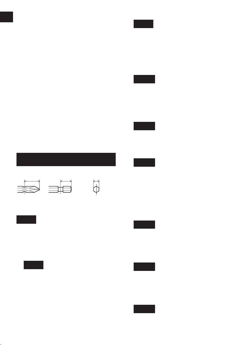
EYFLA4A/EYFLA5A/EYFLA7A/EYFLA8A
EYFLA4AR/EYFLA5AR/EYFLA7AR/EYFLA8AR
12 mm
(15/32")
9 mm – 9.5 mm
(23/64" – 3/8")
6.35 mm
(1/4")
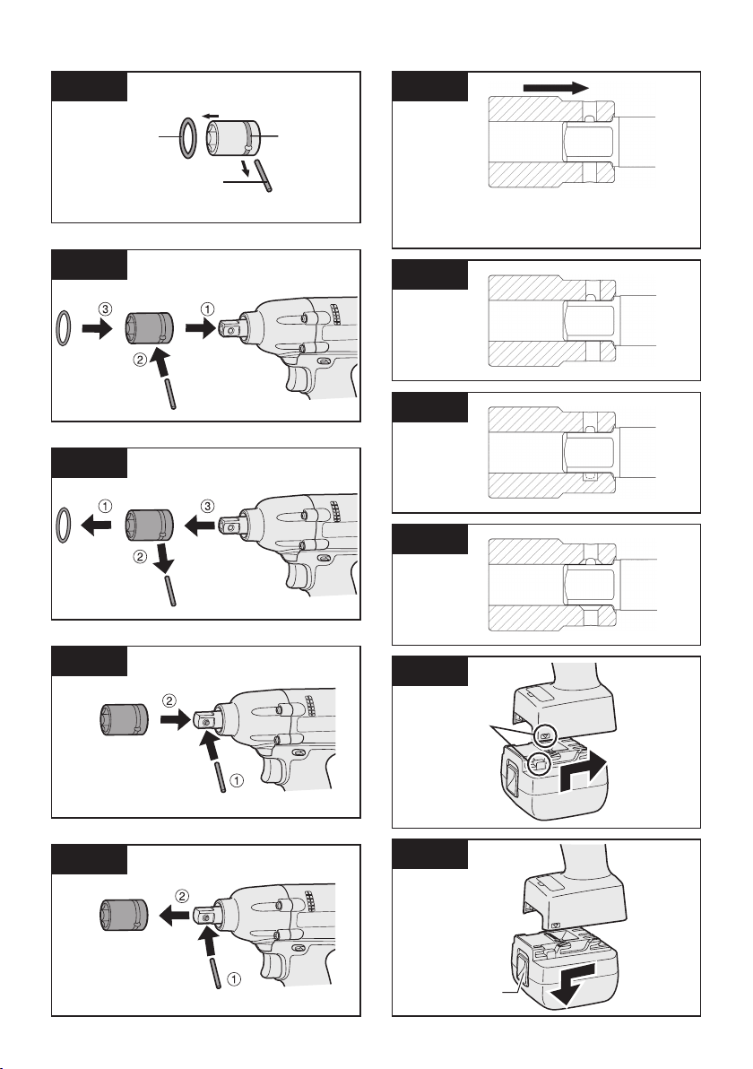
Attaching Socket (Pin type)
Remove the socket’s rubber ring and pin.
[Fig.1]
1 Attach the socket to the tool.
2 Insert the pin. (Taking care to align the
pin holes on the socket and tool.)
3 Attach the rubber ring by sliding it into
place over the groove.
[Fig.2]
3 Remove the socket from the tool.
[Fig.3]
Attaching Socket (Pin-detent)
1 Depress the pin-detent on the square
drive.
2 Attach the socket to square drive.
3 Make sure the socket is securely
attached to the square drive.
[Fig.4]
Removing Socket (Pin-detent)
1 Insert a small rod into the hole on the
socket.
Depress the pin-detent, then detach the
2
socket.
[Fig.5]
CAUTION:
• When attaching a socket to the driver,
verify that the socket and pin-detent do
not interfere with one another.
[Fig.6]
• Some sockets may not function well with
the driver due to their shape. Avoid use
of sockets such as the following:
1
Sockets shaped so that the pindetent makes contact with the side
of the socket’s pin hole when the
socket is attached to the driver.
The pin-detent will be subjected to
excessive force, possibly damaging it.
[Fig.7]
2 Sockets with a pin hole on one
side only
You may be unable to remove the
socket if it is attached in the wrong
orientation.
[Fig.8]
NOTE:
Be sure to attach the rubber ring to
prevent the pin from falling out.
Removing Socket (Pin type)
1 Remove the rubber ring.
2 Remove the pin.
-
14 -
3 Sockets whose pin holes have
beveled edges
The socket will not be held in
place with sufficient force, so that
it may come off during use.
[Fig.9]
Attaching or Removing
Bat tery Pack
1. To connect the battery pack:
Align the highlighted marker points
and attach battery pack.
• Slide the battery pack until it locks
into position.
[Fig.10]
2. To remove the battery pack:
Push down the button and slide the
battery pack forward.
[Fig.11]
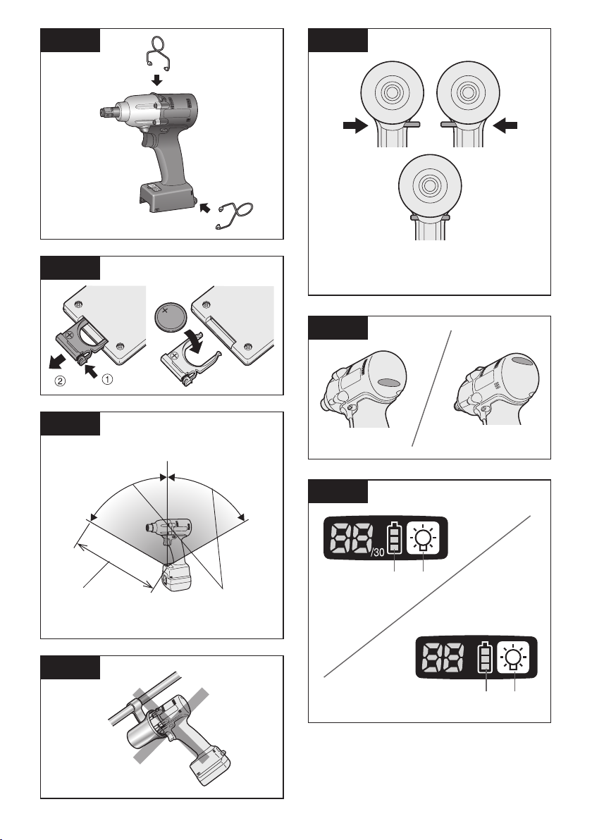
Attaching the tool hanger
[Fig.12]
V.
OPERATION
WARNING
Do not inhale any smoke emitted from the
tool or battery pack as it may be harmful.
Before Using the Remote
Control (Available as an
optional accessory)
Insert the battery
[Fig.13]
1. Pull out the battery holder.
1 Push in on the fastener as indicated
by the arrow.
2 Pull out the holder.
2. Insert the battery and push the holder
back in.
NOTE:
• If the tool does not respond to the
wireless remote control even when
the remote control is operated close
to the tool, the battery (CR2025) is
dead. Replace it with a fresh battery.
• The included battery is provided for
sample use and may not last as long
as commercially available batteries.
Wireless remote control range
[Fig.14]
The remote control should be operated
within approximately 50 cm and approximately 60° vertically and horizontally of
the perpendicular relative to the infrared
receiver on the tool.
• Under the following circumstances, you
may not be able to operate the tool,
even within this range.
- If there is an object between the remote
control’s transmitter and the tool’s receiver.
- Use outdoors or in other environments
where the remote control receiver is
expos ed to a strong light source, or
when the remote control transmitter or
receiver is dirty may cause the tool to
fail to respond, even when the remote
control is used within the operating
range.
[Main Unit]
CAUTION:
If a tool holder is used with the Panasonic
EYF series assembly tools, make sure
the tool’s trigger switch doesn’t hit the tool
holder. It may run the tool accidentally and
result in battery failure by unexpected battery
discharge.
[Fig.15]
CAUTION:
When storing or carrying the tool, set the
Forward/Reverse lever to the center position
(switch lock).
NOTE:
Exercise caution to ensure no objects
come into contact with the tool’s trigger
switch.
If an object comes into contact with
the tool’s trigger switch, even while the
Forward/Reverse lever is in the center
position (locked), a small amount of electric
current may continue flowing, which may
cause an excessive discharge from the
battery pack and subsequent battery pack
failure.
-
15 -

Switch and Forward/Reverse
EN EN
Lever Operation
[Fig.16]
1. Push the lever for forward or reverse
rotation. Check the direction of the
lever before using.
2. Depress the trigger switch slightly to
start the tool slowly.
3. Speed will increase by pressing the
trigger. The tool stops working immediately by releasing the trigger.
4. When done with an application, lock
the switch by centering the lever.
NOTE:
The more the speed control trigger is pulled,
the higher the speed becomes.
CAUTION:
When operating the tool by pulling the trigger, there may be a momentary lag before
rotation starts. This does not signal a malfunction.
* This lag occurs as the tool’s circuitry
starts up when the trigger is pulled for the
first time after installing a battery pack
or after the tool has not been used for
at least 1 minute (or at least 5 minutes
when the LED is on). Rotation will start
without any lag during second and subsequent operations.
Tightening confirmation lamp
The tightening confirmation lamp can
be used to check whether the torque
control function was activated.
[Fig.17]
Tool status Lamp display
Tightening complete
(with torque control
function operation)
• Tightening not complete
Tightening complete with
•
retightening within 1 second
The automatic stop
function has been
activated.
Green
(For approx. 2
seconds)
Red
(For approx. 2
seconds)
Red
(For approx. 5
minutes)
CAUTION:
• When the tool stops automatically
after the switch is released during
impact-mode tightening and then
reengaged within 1 second, the red
lamp will light up to indicate the risk
of excessive torque application as a
result of retightening.
NOTE
• The tightening confirmation lamp
will not turn on under the following
conditions:
• When the torque clutch is set to “F”
• During reverse rotation operation
• The lamp turns off when the tool is
in operation.
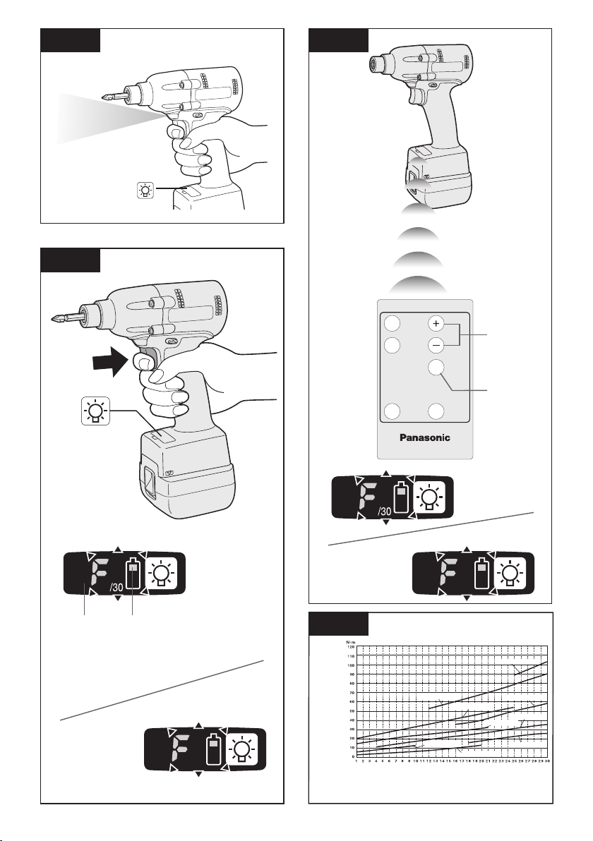
Control Panel
[Fig.18]
(1) LED light
[Fig.18 (1), 19]
Before the use of LED light, always pull the
power switch once.
Press
The light illuminates with very low current, and
it does not adversely affect the performance
of the tool during use or its battery capacity.
Caution: DO NOT STARE INTO BEAM.
Use of controls or adjustments or performance of procedures other than those
specied herein may result in hazardous
radiation exposure.
(2) The battery indication lamp
[Fig.18 (2)]
• Use the battery indication lamp to check
the LED light on button.
CAUTION:
•
The built-in LED light is designed to illuminate the small work area temporarily.
• Do not use it as a substitute for a
regular flashlight, since it does not
have enough brightness.
• LED light turns off when the tool
has not been used for 5 minutes.
how much power is left in the battery.
-
16 -
• Battery life varies slightly with ambient
temperature and battery characteristics.
The lamp is designed to provide a rough
indication of remaining battery life.
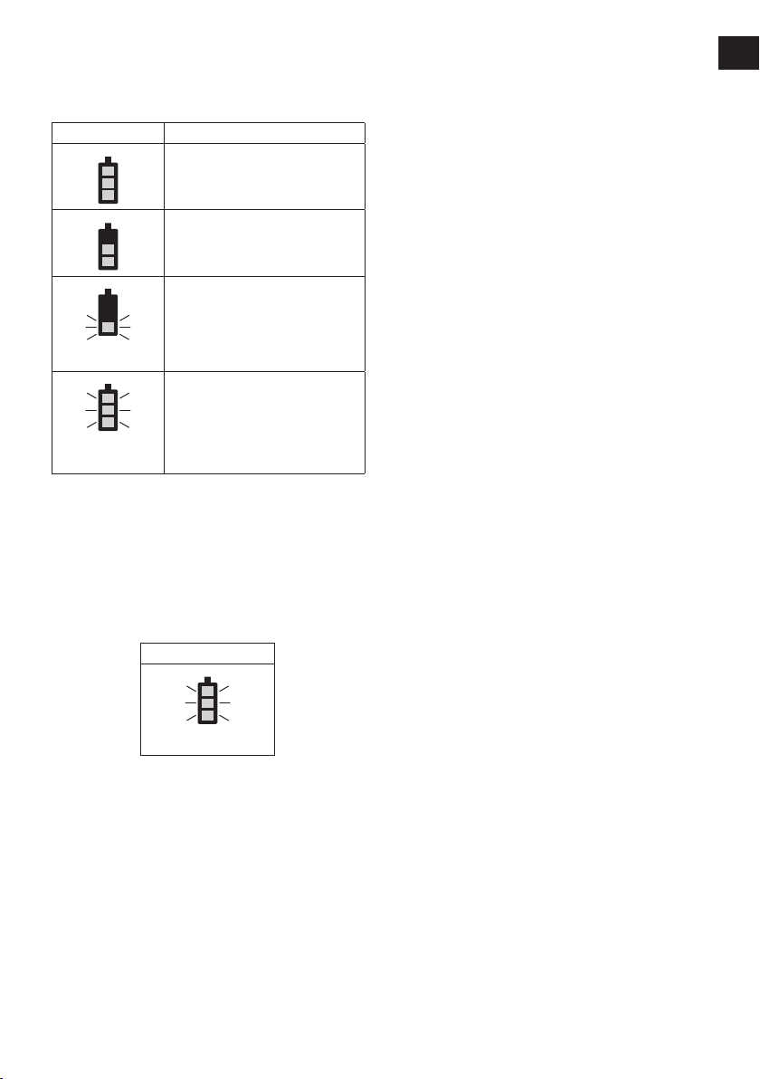
Indicator Battery status
Fully charged
Approx. 40% or less
remaining
Flashing Approx. 20% or
less remaining (indicates
need to recharge battery)
The battery pack will need
Flashing
Flashing
to be charged soon.
No charge
The battery pack needs to
be charged.
(The tool’s automatic
power-off function will
activate at this stage.)
Automatic power-off function
• The automatic power-off function is
designed to prevent a loss of tightening torque due to reduced battery voltage. Once it has been activated, the tool
will not operate until the battery pack has
been charged (or replaced with a fresh
unit), even if the trigger is depressed.
Indicator
Flashing
NOTE:
• All 3 bars on the battery indication
lamp will flash when the automatic
power-off function is activated.
• When the battery indication lamp
begins flashing, the battery pack
should be charged (or replaced with
a fresh unit) immediately.
• Be sure to fully charge the battery
pack in question after activation of
the automatic power-off function.
Failure to do so may prevent the
automatic power-off function from
being properly deactivated.
-
(3) The torque control function
• The torque control function calculates
the load from the motor’s rotational
angle during the hammer impact and
determines that the bolt has been properly seated when a preset load value
is exceeded. Driving is then automatically stopped after a preset number of
impacts have been delivered to the bolt.
CAUTION:
• Always check the tool’s tightening
torque before use. Improper tool
operation may result in excessive or
inadequate tightening.
• Always operate the tool with the
switch fully engaged. The torque
control function will not operate
when the switch is not sufficiently
engaged, preventing the tool from
stopping automatically.
• In work where a heavy load comes
to bear during tightening, the load
may be interpreted as the seating
of the bolt, preventing the bolt from
being completely tightened.
• Repeated tightening of the same
bolt may break the bolt or deform
the material into which the bolt is
being driven as a result of excessive tightening.
• The tightening torque value and precision vary with factors such as the
material into which the bolt is being
driven and the condition of the socket
being used. Adjust the torque as necessary for the work being performed.
Bolt tightening torque varies due to
the factors described below.
1) Bolt
• Bolt diameter: Tightening torque generally increases with bolt diameter.
• Torque coefficient (indicated by the
bolt manufacturer), grade, length, etc.
2) Other
• Bit and socket condition: Material,
amount of play, etc.
• Use of a universal joint or socket adapter
• User: Manner in which the tool is
applied to the bolt, strength with
which the tool is held, manner in
which the tool’s switch is engaged
• Condition of object being tightened:
Material, seating surface finish
17 -
Setting the tool to configuration
3…28
1F30 229
3…38
1F40 239
EN EN
mode
1. Turn off the control panel.
• If the control panel is on, remove
and then reinsert the battery pack.
2. Engage the switch while pushing the
button and then release both the
button and the switch.
• After all the LED lamps have turned
off, the control panel will flash and
change to configuration mode.
[Fig.20]
NOTE:
• Tools ship from the factory set to “F”
mode (torque control function off).
• The control panel will turn off if the
tool is not operated for a period of 5
minutes.
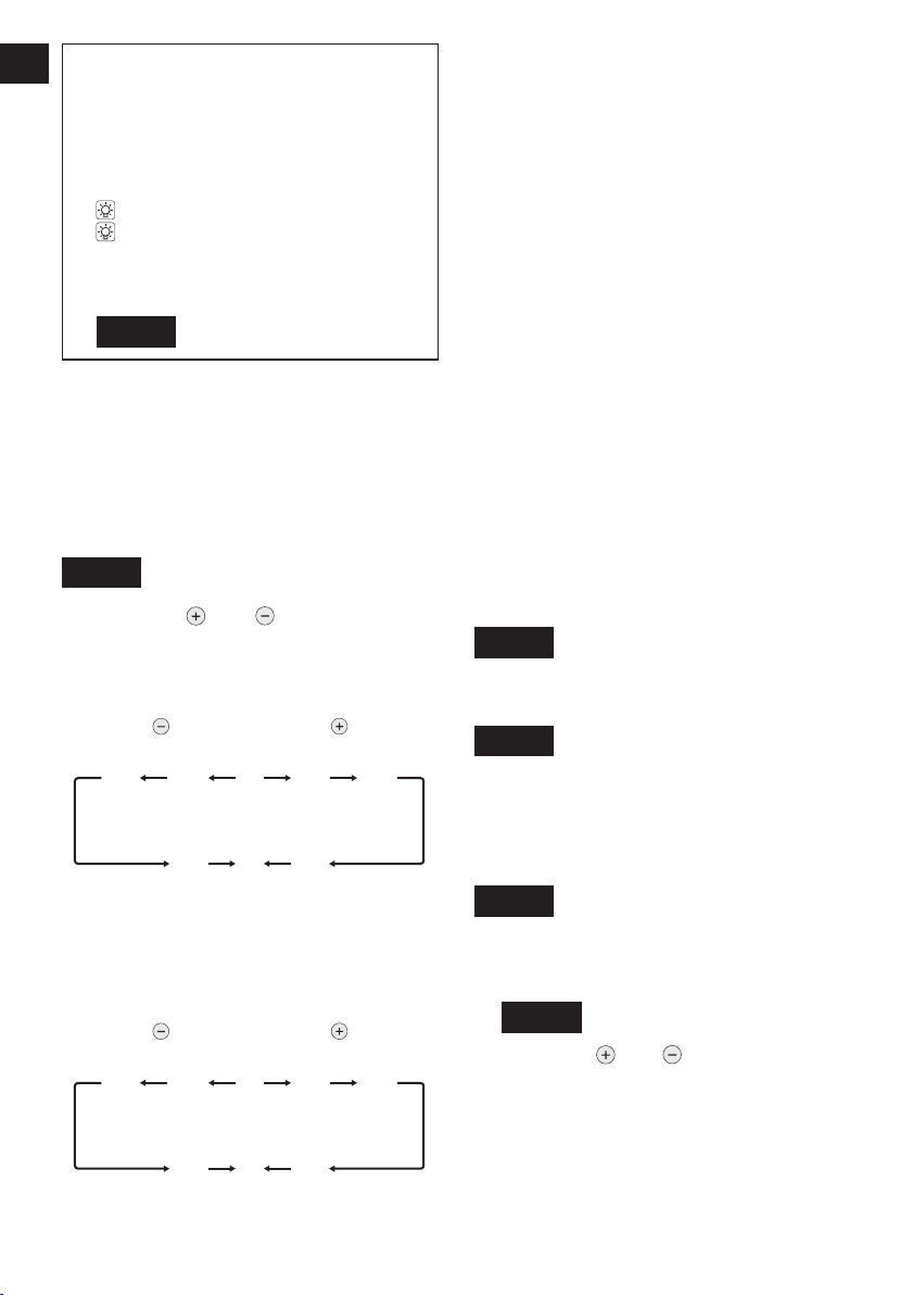
Configuring the torque clutch setting
[Fig.21]
1. Press the and buttons to select
the clutch setting that is appropriate
• You can select from 40 torque clutch
settings (1 to 40).
• Use figures from the Tightening
Torque Chart to guide your selection
of torque clutch setting. (See the following tightening torque chart)
2. Press the OK button to accept the
selected torque clutch setting.
• The control panel will stop flashing
and light up.
CAUTION:
•
You must press the OK button in order
for the selected setting to take effect.
• Be sure to verify the new value after
changing the setting.
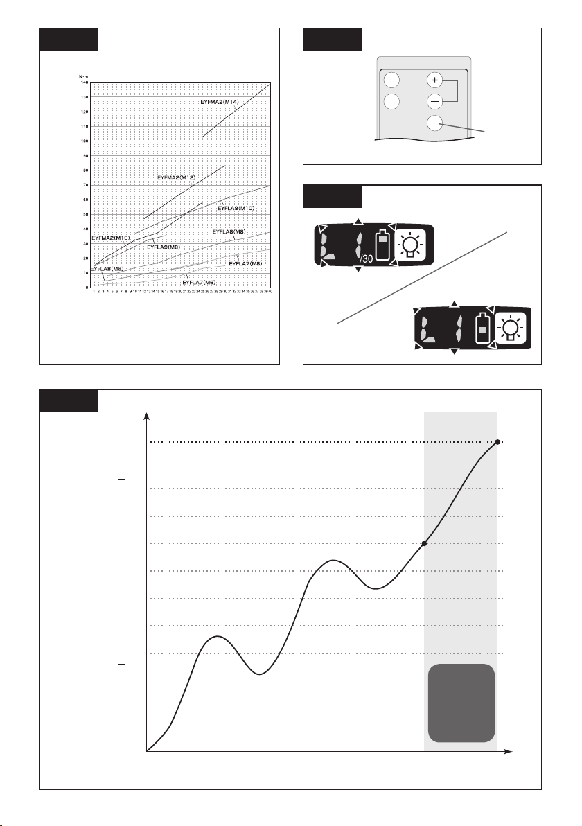
Tightening Torque Chart (for Reference
Use)
e values illustrated on this chart were
Th
measured under the conditions described
below and are provided for reference purposes. Actual tightening torque varies with
ambient conditions (the particular bolt being
tightened, hardware being used, method of
holding the bolt in place, etc.).
[EYFLA4, EYFLA5, EYFLA6, EYFMA1]
[Fig.22]
for the work being performed.
[EYFLA4, EYFLA5, EYFLA6, EYFMA1]
As the button
is pressed
As the button
is pressed
[EYFLA7, EYFLA8, EYFLA9, EYFMA2]
[Fig.23]
• “F” indicates that the torque control
function is off.
• You can select from 30 torque clutch
settings (1 to 30).
[EYFLA7, EYFLA8, EYFLA9, EYFMA2]
As the button
is pressed
• “F” indicates that the torque control
As the button
is pressed
function is off.
Measurement conditions
• Temperature: Room temperature
(20°C/68°F)
Setting the snug point detection level
[Fig.24]
1. Press the A button.
• The snug point detection level setting
value will be displayed.
[Fig.25]
2. Press the and buttons to set the
best snug point detection level for the
work you’re performing.
3. Press the OK button to accept the
number of torque stages and the
snug point detection level.
The tool’s panel will flash and then light
up continuously.
-
18 -
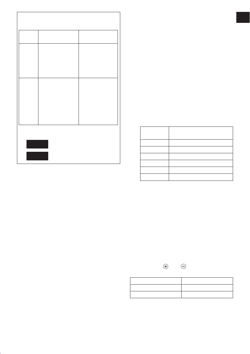
Snug point detection level guidelines
[EYFLA4, EYFLA5, EYFLA6, EYFMA1]
Display
L1
L2
Snug point
detection level
Low
(Use for work
characterized by
low loads before
the snug point is
reached.)
High
(Use for work
characterized by
high loads before
the snug point is
reached.)
Applications
(reference)
• Tightening
bolts in
materials that
are easily
cracked or
deformed, etc.
• Tightening
bolts in
materials with
misaligned
holes, etc.
• Tightening
self-tapping
screws, etc.
[EYFLA7, EYFLA8, EYFLA9, EYFMA2]
[Fig.26]
[Fig.27]
CAUTION:
• The setting will not be changed until you
press the OK button.
• After changing the setting, be sure to check
the new setting value. (See “Checking Tool
Settings.”)
[
EYFLA4, EYFLA5, EYFLA6, EYFMA1
• Set the snug point detection level from
“L1.” Setting the snug point detection
level from “L2” may result in cracking or
deformation of the target material.
• If the tool stops before the snug point at
snug point detection level “L1,” set the
snug point detection level to “L2.”
• Changing the snug point detection level
from “L1” to “L2” may increase the torque.
Set the number of torque stages again
after making this change.
[EYFLA7, EYFLA8, EYFLA9, EYFMA2]
• Set the snug point detection level from
“L1.” Setting the snug point detection
level from “L7” may result in cracking or
deformation of the target material.
• If the tool stops before the snug point at
snug point detection level “L1,” set the
snug point detection level to “L7.”
• Changing the snug point detection
level from “L1” to “L7” may increase the
torque. Set the number of torque stages again after making this change.
IMPORTANT INFORMATION:
• Pressing the A button toggles the display between the snug point detection level setting value and the number of torque stages setting value.
• The tool ships with the snug point
detection level set to “L1.”
• When the number of torque stages
has been set as shown below, the
snug point detection level cannot be
switched from “L1” to “L2 ~ L7.”
Model
EYFLA4 1 to 8
EYFLA5 1 to 3
EYFLA7 1 to 40
EYFLA8 1 to 40
EYFLA9 1 to 40
EYFMA2 1 to 40
Number of torque stages
setting
Cross thread reduction function
[EYFLA7, EYFLA8, EYFLA9, EYFMA2]
The tool runs in reverse approximately 360° before running forward to assist
]
in the alignment of the threads to help
reduce cross threads.
1. Set the tool to setting configuration
mode. (See page 18.)
2. Press the D button once.
The cross thread reduction function setting
value will be displayed.
3. Press the and buttons to change
the setting to ON or OFF.
Display Function
R0 OFF
R1 ON
4. Press the OK button to accept the
new setting.
-
19 -
Rundown error detecting function
EN EN
(EYFLA7, EYFLA8, EYFLA9,
EYFMA2)
The rundown error detecting function
causes a red indicator to flash if work
ends more quickly than a set time, for
example due to retightening of a previously tightened fastener or binding of the
screw’s thread.
1. Set the tool to setting configuration
mode. (See page 18.)
2. Press the B button twice.
The rundown error detecting function setting value will be displayed.
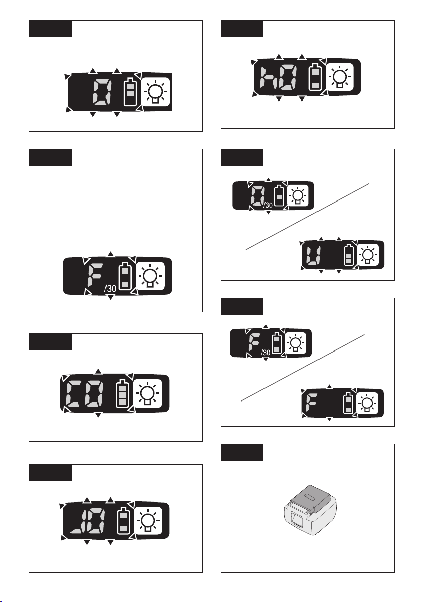
[Fig.28]
3.
Press the and buttons to change the
time as desired.
Buttons Display Seconds
30 3
1 0.1
0 OFF
4. Press the OK button to accept the
selected setting.
When the cross thread reduction function
is ON, the set time will be counted after
the tool operates in reverse for approximately 360°.
Radio signal range limitation
function on/off setting (EYFLA4AR,
EYFLA5AR, EYFLA5PR, EYFLA5QR,
EYFLA6JR, EYFLA6PR, EYFLA7AR,
EYFLA8AR, EYFLA8CR, EYFLA8PR,
EYFLA9CR, EYFLA9PR, EYFMA1JR,
EYFMA1PR, EYFMA2CR, EYFMA2PR
1. Set the tool to configuration mode.
(See page 18.)
2. Press the C button.
The control panel will begin flashing.
•
Display: The letter “F” ashes on and off.
Battery indication lamp: The upper and lower
bars of the battery ash on and off.
[Fig.29]
3. Press the C button again.
• Radio signal range limitation function
ON/OFF setting value will be displayed.
[Fig.30]
4. Press the and buttons to set
radio signal range limitation function
ON/OFF.
Display
Radio signal
range limitation
function mode
C0 OFF
C1 ON
Status
Tool is operational in the absence of communications with
the Assembly Qualier.
Tool is not operational
in the absence of com
munications with the As-
sembly Qualier.
5. Press the OK button to accept the
new setting.
Factory settings
• Radio signal range limitation function
setting: C0 (OFF)
NOTE:
• For more information about how to register
the tool and Assembly Qualifier, see the
Assembly Qualifier instruction manual.
Tightening time reminder
(EYFLA7, EYFLA8, EYFLA9,
EYFMA2)
The tool is locked when it reaches the set
tightening time, and the main unit stops
operation. This feature is convenient for
regular inspection of the tool performance.
1. Set the tool to setting configuration
mode. (See page 18.)
2. Press the C button twice.
)
The setting value will be displayed.
3. Press and buttons as required to
change the time.
Operation Display Tightening time
99 99 hours
1 1 hour
0 OFF
-
4. Press the OK button to accept the new
setting.
-
20 -
NOTE:
• When the remaining time prior to the
tightening time is less than 1 hour, the
display will alternate between the “set
value” and “-1”.
If the current tightening time remains
unchanged and the inspection duration
is extended, the new set value must be
greater than the current one.
When it reaches the set time, the
display alternates between the set
value and 0.
Buzzer setting
(EYFLA7, EYFLA8, EYFLA9,
EYFMA2)
You can select from three buzzer modes.
1. Set the tool to setting configuration
mode. (See page 18.)
2. Press the A button twice.
The current setting value will be displayed.
3. Press the and buttons to set the
desired value.
Display Function
b0 No buzzer
b1
Buzzer accompanying green indicator
b2 Buzzer accompanying red indicator
4. Press the OK button to accept the new
setting.
NOTE:
The tool ships with the buzzer mode set to
b0 by default.
LED light setting
(EYFLA7, EYFLA8, EYFLA9,
EYFMA2)
You can select from two LED light modes.
1. Set the tool to setting configuration
mode. (See page 18.)
2. Press the B button once.
The current setting value will be displayed.
3. Press the and buttons to set the
desired value.
Display Function
d1 Linked to LED light button
d2 Linked to trigger switch operation
4. Press the OK button to accept the new
setting.
NOTE:
The tool ships with the LED light mode set
to d1 by default.
Speed control function
(EYFLA7, EYFLA8, EYFLA9,
EYFMA2)
The speed (RPM) can be changed with the
amount of depression of the trigger.
1. Set the tool to setting configuration
mode. (See page 18.)
2. Press the B button three times.
The setting value will be displayed.
3. Press the and buttons to set the
desired value.
Operation Function
P0 Speed control ON
P1 Speed control OFF
4.
Press the OK button to accept the new
setting.
Setting the undetect time
(EYFLA7, EYFLA8, EYFLA9,
EYFMA2)
To set the time to undetect the function of
“snug point detection level” from the start
tightening, do as follows.
1. Set the tool to the configuration mode.
(See page 18.)
2. Press button A three times.
•
The current set value is displayed, and the
main unit panel starts flashing.
Display: J0 ashing.
Battery capacity indicator: The upper and
lower bars ash.
[Fig.31]
3. Press and buttons as required to
change the time.
Operation Display Seconds
30 3
1 0.1
J0 OFF
4. Press the OK button to accept the new
setting.
-
21 -
Setting the impact speed
EN EN
corresponding to the length
of the socket used
(EYFLA9, EYFMA2)
To set the stable impact speed based on the
length of the socket used, do as follows:
1. Set the tool to the configuration mode.
(See page 18.)
2. Press button D three times.
• The current set value is displayed, and
the main unit panel starts flashing.
Display: h0 ashing.
Battery capacity indicator: The upper
and lower bars ash.
[Fig.32]
3. Press and buttons as required to
change the value.
Display Impact Speed Standard
h0
h1
h2
4. Press the OK button to accept the new
setting.
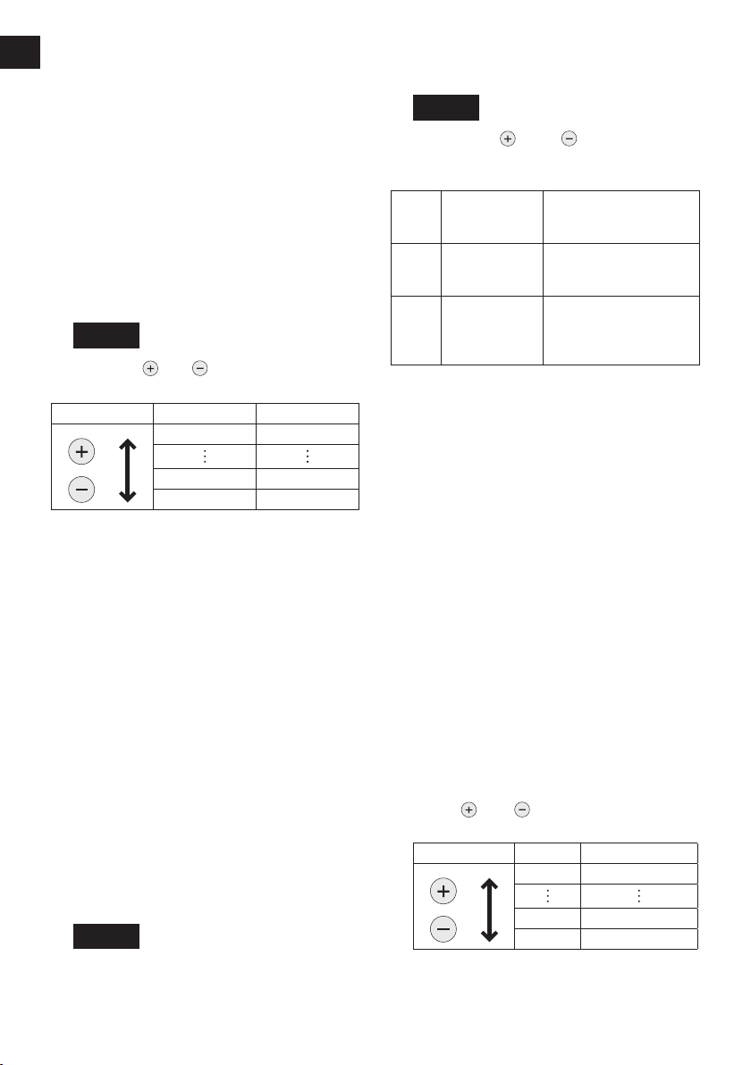
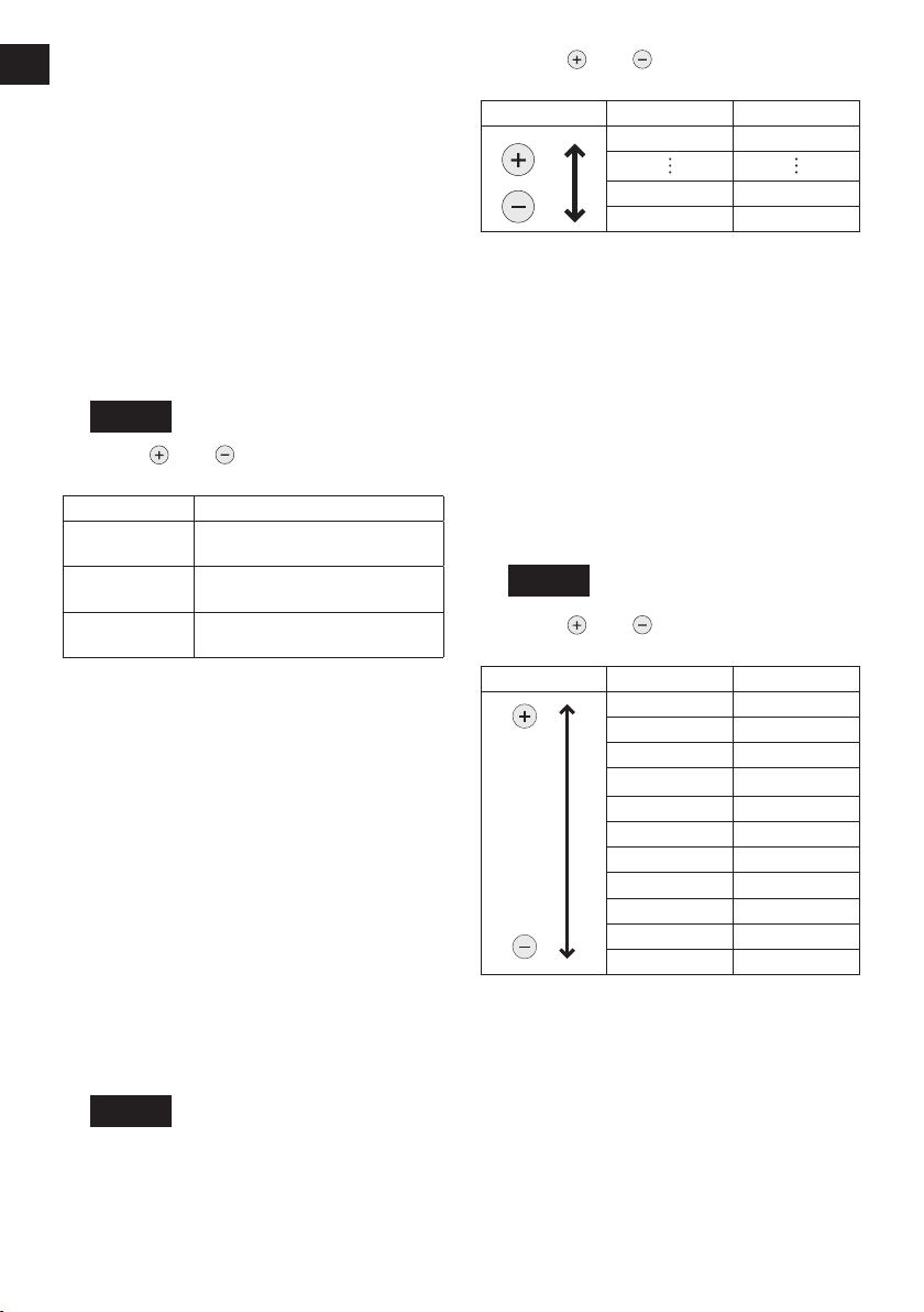
Setting use interval
Use interval is set to prevent the screwdriver
from continuing its operation when the
tool is automatically stopped due to the
implementation of the torque correction
feature. This setting is valid even when the
switch is off.
1. Set the tool to the configuration mode.
(See page 18.)
[EYFLA4, EYFLA5, EYFLA6, EYFMA1]
2. Press button B.
• The main unit panel starts flashing.
Display: 0 flashing intermittently.
Battery capacity indicator: The middle
bar flashes intermittently.
[Fig.33]
Standard socket
(high speed)
Up to 150 mm socket
(medium speed)
Up to 250 mm socket
(low speed)
3. Press and buttons as required to
set the time.
Operation Display Seconds
30 3
1 0.1
0 OFF
4. Press OK to confirm the settings.
• The control panel stops flashing and lights
up to display the torque clutch settings.
NOTE:
Check the new value after you change the
settings.
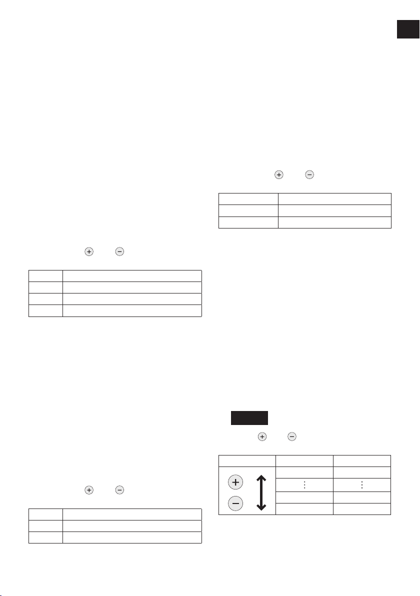
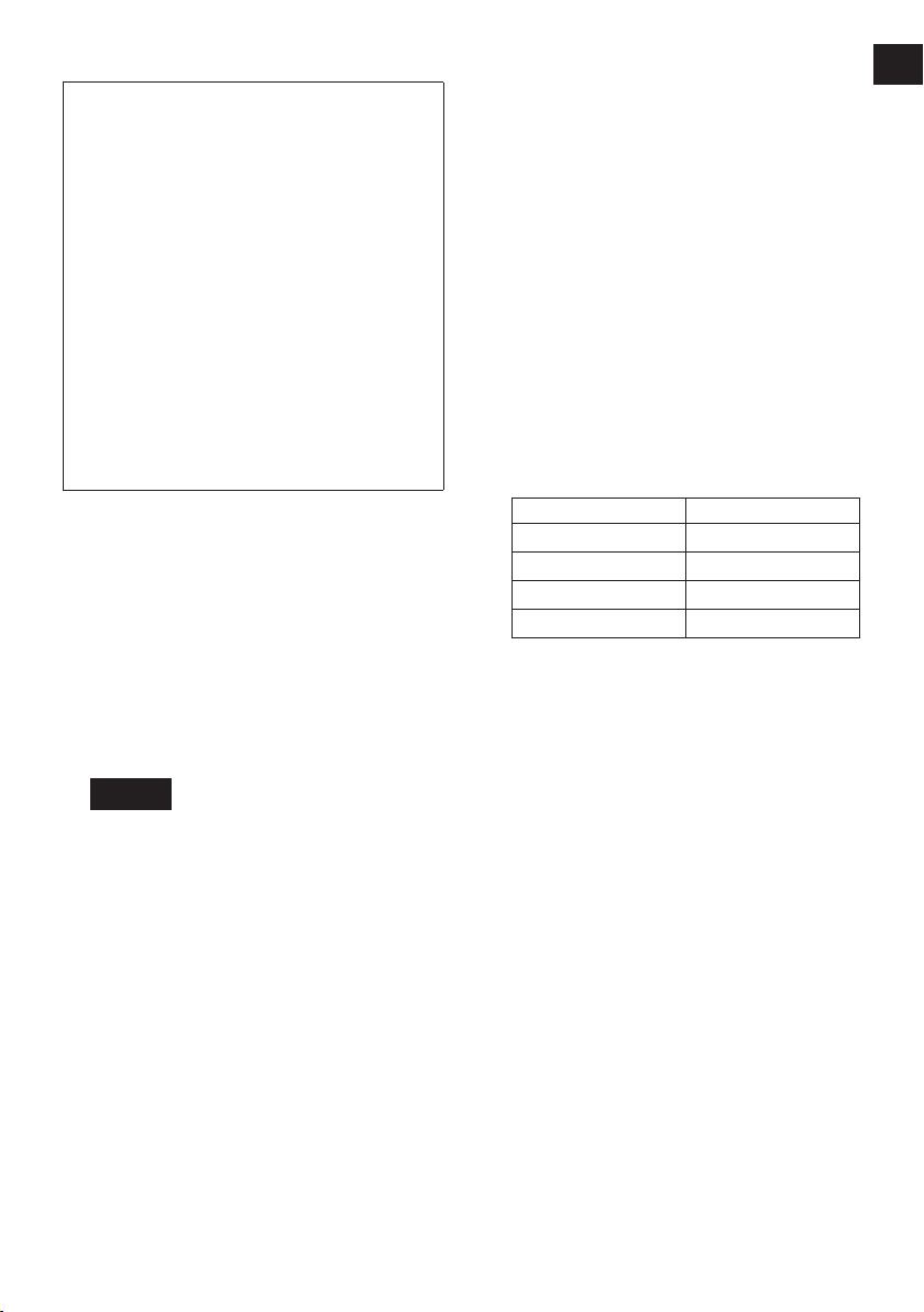
[EYFLA7, EYFLA8, EYFLA9, EYFMA2]
2. Press button D twice.
• The current set value is displayed, and
the main unit panel starts flashing.
Display: U flashing.
Battery capacity indicator: The upper and
lower bars flash.
[Fig.33]
3. Press and as required to change
the time.
Operation Display Seconds
U9 3
U8 2.5
U7 2
U6 1.5
U5 1.2
U4 1
U3 0.7
U2 0.5
U1 0.3
U0 0.1
U OFF
4. Press the OK button to accept the new
setting.
• The control panel stops flashing and lights
up to display the torque clutch settings.
NOTE:
Check the new value after you change the
settings.
-
22 -
Initializing all settings
Factory settings
• Torque clutch setting: “F” (torque control
function off)
• Interval setting: U or 0 (OFF)
[EYFLA9, EYFMA2]
• Snug point detection level → L1
• Cross thread reduction function → R0
• Rundown error detecting function → 0
• Tightening time reminder → 0
• Radio signal range limitation function
→ C0
• Buzzer setting → b0
• LED light setting → d1
• Speed control setting → P0
• Undetect time setting → J0
• Impact speed setting corresponding to
the length of the socket used → h0
• This section explains how to revert all tool
settings to their default values at the time of
shipment from the factory.
• The error display will be turned off.
1. Set the tool to the setting configuration
mode.
(See page 18.)
2. Press the C button.
The control panel will begin flashing.
Display: The letter “F” flashes on and off.
Battery indication lamp: The upper and
lower bars of the battery flash on and off.
[Fig.34]
3. Press the OK button to accept the
selected setting.
The control panel will stop flashing and
light up.
Checking Tool Settings
(EYFLA4, EYFLA5, EYFLA6,
EYFMA1)
• This section describes how to have the
tool display current settings for approximately 3 seconds when the tool is
stopped.
• You cannot check tool settings when
the control panel is turned off. First,
engage the switch briefly to reactivate
the display.
Checking the torque clutch setting
Press the A button.
• Control panel display
Display: The torque set lights up.
Battery indication lamp: The upper bar of
the battery flashes on and off.
Checking the interval
Press the B button.
• Control panel display
Display: The interval set lights up.
Battery indication lamp: The middle bar of
the battery flashes on and off.
Checking tool circuits
Press the D button.
• Control panel display
Display: The torque set display lights up.
Battery indication lamp: The middle and
lower bars of the battery flash on and off.
Display Tool circuit
H6 EYFLA4
H7 EYFLA5
H8 EYFLA6
H9 EYFMA1
NOTE:
If you engage the switch while a setting
is being displayed, the control panel will
revert to the torque clutch setting display.
CAUTION:
The torque set display is not intended to
be used to identify the type of drive component parts (hammer, etc.) used in a particular tool.
Checking Tool Settings
(EYFLA7, EYFLA8, EYFLA9,
EYFMA2)
• This section describes how to have the
The current set value will display for
another 2 seconds after the tool stops
operation.
• The set status cannot be checked when
the tool panel is off. You can press the
trigger switch once to turn on the panel.
-
23 -
 Loading...