

Panasonic EYFLC1A Owner's Manual
Before operating this unit, please read these instructions completely and save this manual for future use.
Lire entièrement les instructions suivantes avant de faire fonctionner l’appareil et conserver ce mode d’emploi
à des fins de consultation ultérieure.
Antes de usar este aparato por primera vez, lea todas las instrucciones de este manual y guarde el manual
para poderlo consultar en el futuro.
Cordless Oilpulse Driver
Perceuse hydraulique sans l
Destornillador de impulso de aceite inalámbrico
Operating Instructions
Instructions d’utilisation
Manual de instrucciones
Model No : EYFLC1A
Index/Index/Indice
English : Page 4
Français : Page 13
Español : Página 23
FUNCTIONAL DESCRIPTION
DESCRIPTION DES FONCTIONS
DESCRIPCIÓN FUNCIONAL
(A)
(J)
(K)
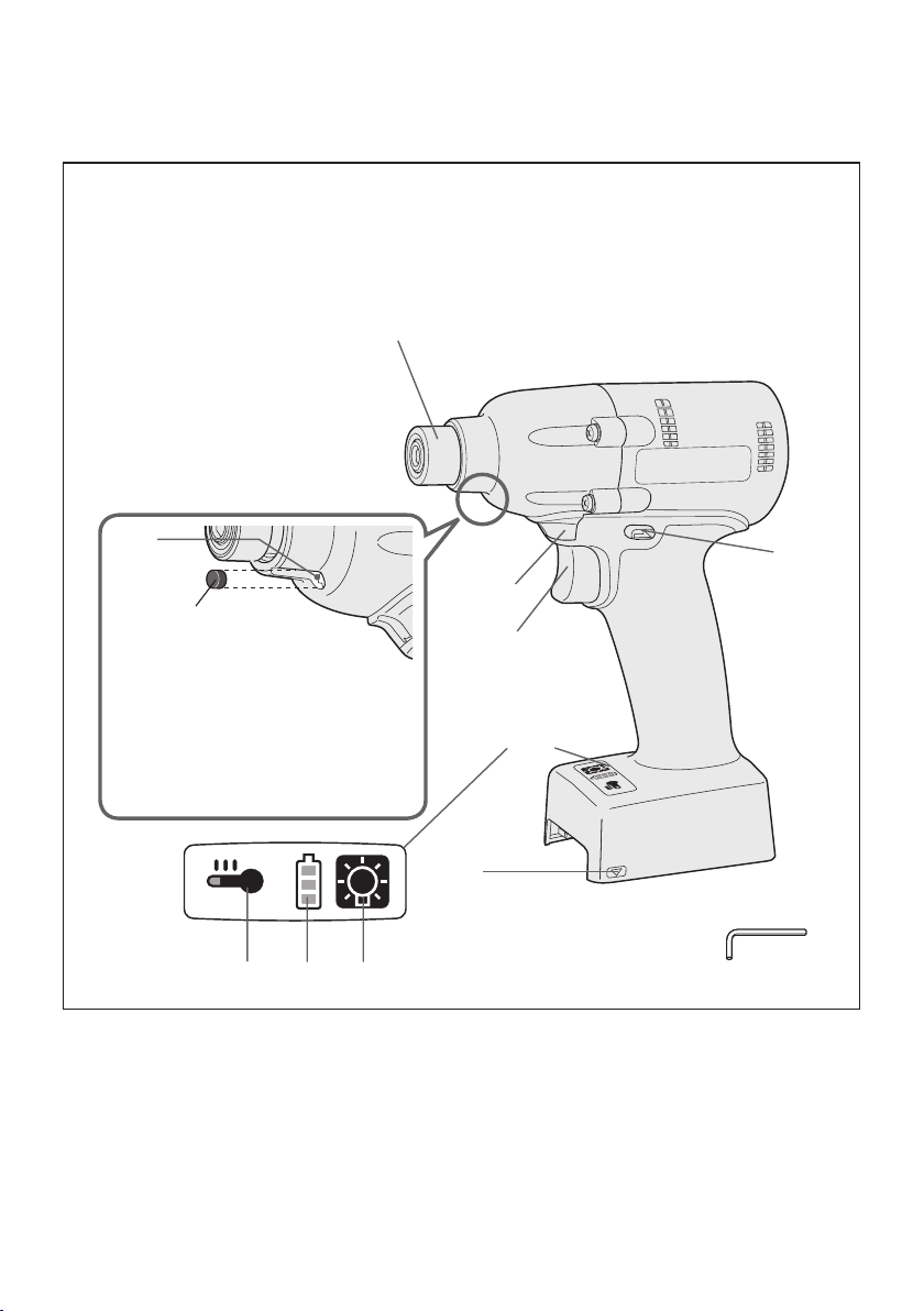
The tool ships with the rubber
stopper inserted.
L'outil est livré avec un
bouchon en caoutchouc inséré.
La herramienta se envía con
tope de caucho insertado.
(G)
(E)(F)
(B)
(I)
(H)
(D)
(C)
(L)
-
2 -

(A) 6.35 mm (1/4") hex quick connect chuck
(B) Forward/Reverse lever
(C) Alignment marks
(D) Control panel
(E) LED light on/off button
(F) Battery indication lamp
(G) Overheat warning lamp
(H) Variable speed control trigger
(I) LED light
(J) Relief valve
(K) Rubber stopper
(L) Hexagonal head wrench
(A) Mandrin de connexion rapide hexagonal 6,35 mm (1/4”)
(B) Levier d’inversion marche avant/marche arrière
(C) Marques d’alignement
(D) Panneau de commande
(E) Bouton Marche/Arrêt de la lumière DEL
(F) Témoin indicateur de la batterie
(G) Lampe d'avertissement de surchauffe
(H) Gâchette de commande de vitesse
(I) Lumière DEL
(J) Soupape de surpression
(K) Bouchon en caoutchouc
(L) Clé Allen
(A) Mandril hexagonal de conexión rápida de 6,35 mm (1/4”)
(B) Palanca de avance/marcha atrás
(C) Marcas de alineación
(D) Panel de control
(E) Botón encendido/apagado de luz LED
(F) Lámpara de indicadora de la batería
(G) Lámpara de aviso de sobrecalentamiento
(H) Disparador del control de velocidad variable
(I) Luz LED
(J) Válvula de escape
(K) Tope de caucho
(L) Llave de cabeza hexagonal
-
3 -

I
.
GENERAL SAFETY
RULES
WARNING! Read all instructions
Failure to follow all instructions listed
below may result in electric shock, fire
and/or serious injury. The term “power
tool” in all of the warnings listed below
refers to your mains operated (corded)
power to o l a n d battery operated
(cordless) power tool.
SAVE THESE INSTRUCTIONS
Work Area Safety
1) Keep work area clean and well lit.
Cluttered or dark areas invite accidents.
2)
Do not operate power tools in explosive
atmospheres, such as in the presence
of flammable liquids, gases or dust.
Power tools create sparks which may
ignite the dust or fumes.
Keep children and bystanders away
3)
while operating a power tool.
Distractions can cause you to lose control.
Electrical Safety
1) Power tool plugs must match the
outlet. Never modify the plug in any
way. Do not use any adapter plugs
with earthed (grounded) power tools.
Unmodified plugs and matching outlets
will reduce risk of electric shock.
Avoid body contact with earthed or
2)
grounded surfaces such as pipes,
radiators, ranges and refrigerators.
There is an increased risk of electric shock
if your body is earthed or grounded.
3) Do not expose power tools to rain or
wet conditions.
Water entering a power tool will increase
the risk of electric shock.
Do not abuse the cord. Never use
4)
the cord for carrying, pulling or
unplugging the power tool. Keep
cord away from heat, oil, sharp edges
or moving parts.
Damaged or entangled cords increase
the risk of electric shock.
When operating a power tool outdoors,
5)
use an extension cord suitable for
outdoor use.
Use of a cord suitable for outdoor use
reduces the risk of electric shock.
If operating a power tool in a damp
6)
location is unavoidable, use a residual
current device (RCD) protected supply.
Use of RCD reduces the risk of electrical shock.
Personal Safety
1)
Stay alert, watch what you are doing
and use common sense when operating
a power tool. Do not use a power tool
while you are tired or under the influence
of drugs, alcohol or medication.
A moment of inattention while operating
power tools may result in personal injury.
2)
Use safety equipment. Always wear
eye protection.
Safety equipment such as dust mask,
non-skid safety shoes, hard hat, or
hearing protection used for appropriate
conditions will reduce personal injuries.
3)
Avoid accidental starting. Ensure the
switch is in the off position before
plugging in.
Carrying power tools with your finger on
the switch or plugging in the power tools
that have the switch on invites accidents.
4)
Remove any adjusting key or wrench
before turning the power tool on.
A wrench or a key left attached to a
rotating part of the power tool may result
in personal injury.
5)
Do not overreach. Keep proper footing
and balance at all times.
This enables better control of the power
tool in unexpected situations.
6)
Dress properly. Do not wear loose
clothing or jewellery. Keep your
hair, clothing and gloves away from
moving parts.
Loose clothes, jewellery or long hair can
be caught in moving parts.
7)
If dev ices a re provided for th e
connection of dust extraction and
collection facilities, ensure these are
connected and properly used.
Use of these devices can reduce dust
related hazards.
Power Tool Use and Care
1)
Do not force the power tool. Use the
correct power tool for your application.
The correct power tool will do the job
better and safer at the rate for which it
was designed.
2)
Do not use the power tool if the
switch does not turn it on and off.
Any power tool that cannot be controlled
with the switch is dangerous and must
be repaired.
3)
Disconnect the plug from the power
source and/or the battery pack from
-
4 -

the power tool before making any
adjustments, changing accessories,
or storing power tools.
Such prevent ive safety mea sures
reduce the risk of starting the power tool
accidentally.
4)
Store idle power tools out of the reach
of children and do not allow persons
unfamiliar with the power tool or these
instructions to operate the power tool.
Power tools are dangerous in the hands
of untrained users.
5)
Maintain power tools. Check for
misalignment or binding of moving
parts, breakage of parts and any other
condition that may affect the power
tools operation. If damaged, have the
power tool repaired before use.
Many accidents are caused by poorly
maintained power tools.
6)
Keep cutting tools sharp and clean.
Properly maintained cutting tools with
sharp cutting edges are less likely to
bind and are easier to control.
7)
Use the power tool, accessories
and tool bits etc. in accordance with
these instructions and in the manner
intended for the particular type of
power tool, taking into account the
working conditions and the work to
be performed.
Use of the power tool for operations
different from those intended could
result in a hazardous situation.
Battery Tool Use and Care
1) Ensure the switch is in the off position
before inserting battery pack.
Inserting battery pack into power tools
that have the switch on invites accidents.
2)
Recharge only with the cha rger
specified by the manufacturer.
A charger that is suitable for one type
of battery pack may create a risk of fire
when used with another battery pack.
3)
Use power tools only with specifically
designated battery packs.
Use of any other battery packs may
create a risk of injury and fire.
4)
When battery pack is not in use, keep it
away from other metal objects like paper
clips, coins, keys, nails, screws, or other
small metal objects that can make a
connection from one terminal to another.
Shorting the battery terminals together
may cause burns, or a fire.
5)
Under abusive conditions, liquid may
be ejected from battery; avoid contact.
If contact accidentally occurs, flush
with water. If liquid contacts eyes,
additionally seek medical help.
Liquid ejected from the battery may
cause irritation or burns.
Service
1) Have your power tool serviced by a
qualified repair person using only
identical replacement parts.
This will ensure that the safety of power
tool is maintained.
II
. INTENDED USE
This tool is a Cordless Oilpulse Driver and can
be used to tighten bolts, nuts, and screws.
III
.
ADDITIONAL SAFETY
RULES
1
) Wear ear protectors when using the
tool for extended periods.
2) Be aware that this tool is always in an
operating condition, since it does not have
to be plugged into an electrical outlet.
3) When screwing or driving into walls, floors,
etc., “live” electrical wires may be encountered. DO NOT TOUCH THE HEX QUICK
CHUCK OR ANY FRONT METAL PARTS
OF THE TOOL! Hold the tool only by the
plastic handle to prevent electric shock in
case you screw or drive into a “live” wire.
4) Do NOT operate the Forward/Reverse
lever when the main switch is on. The battery will discharge rapidly and damage to
the unit may occur.
5) During charging, the charger may become
slightly warm. This is normal.
Do NOT charge the battery for a long period.
6) When storing or carrying the tool, set the
Forward/Reverse lever to the center position (switch lock).
7) Do not strain the tool by holding the speed
control trigger halfway (speed control
mode) so that the motor stops.
8)
Hold power tool by insulated gripping
surfaces, when performing an operation
where the fastener may contact hidden wiring.
Fasteners contacting a "live" wire may make
exposed metal parts of the power tool "live"
and could give the operator an electric shock.
-
5 -
Symbol Meaning
Forward Reverse
Switch lock
V
n
0
Volts
Direct current
No load speed
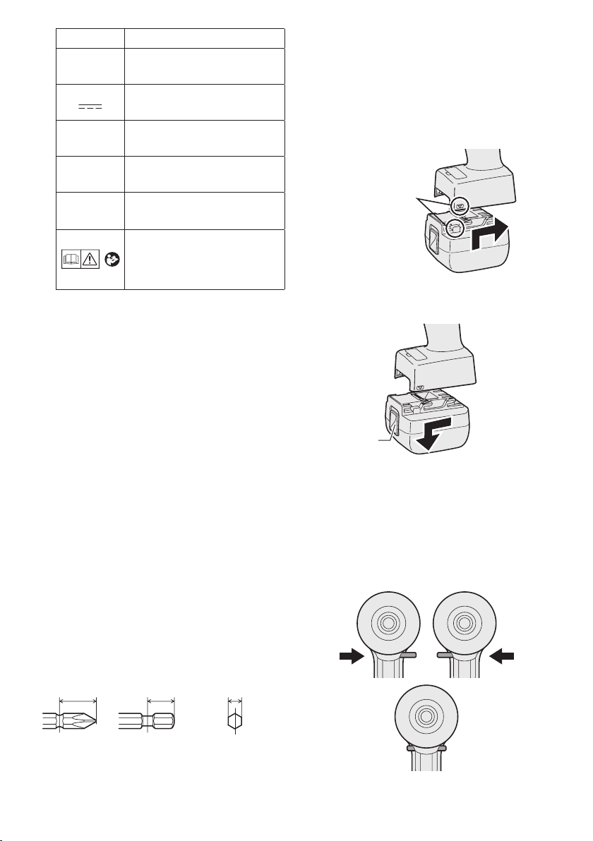
Attaching or Removing Battery Pack
1. To connect the battery pack:
Line up the alignment marks and attach
the battery pack.
Slide the battery pack until it locks into
•
position.
-1
… min
Ah
IV
. ASSEMBLY
Revolutions or
reciprocations per minutes
Electrical capacity of battery
pack
To reduce the risk of
injury, user must read and
understand instruction
manual.
Attaching or Removing Bit
NOTE:
• When attaching or removing a bit, dis
connect battery pack from tool or place
the Forward/Reverse lever in the center
position (switch lock).
1. Hold the collar of quick connect chuck and
pull it out from the tool.
2. Insert the bit into the chuck. Release the
collar.
3. The collar will return to its original position
when it is released.
Pull the bit to make sure it does not come out.
4.
5. To remove the bit, pull out the collar in the
same way.
CAUTION:
• If the collar does not return to its original
position or the bit comes out when pulled
on, the bit has not been properly attached.
Make sure the bit is properly attached
before use.
Alignment
marks
2. To remove the battery pack:
Pull on the button from the front to release
the battery pack.
-
Button
V.
OPERATION
[Main Body]
Switch and Forward/Reverse
Lever Operation
12 mm
(15/32")
9 mm – 9.5 mm
(23/64" – 3/8")
6.35 mm
(1/4")
-
6 -
CAUTION:
To prevent damage, do not operate
Forward/Reverse lever until the bit comes
to a complete stop.
Forward Rotation Switch
Operation
1. Push the lever for forward rotation.
2. Depress the trigger switch slightly to start
the tool slowly.
3. The speed increases with the amount of
depression of the trigger for efficient tightening of screws. The brake operates and
the bit stops immediately when the trigger
is released.
4. After use, set the lever to its center posi
tion (switch lock).
Reverse Rotation Switch
Operation
1.
Push the lever for reverse rotation. Check
direction of rotation before use.
2. Depress the trigger switch slightly to start
the tool slowly.
3. After use, set the lever to its center posi
tion (switch lock).
CAUTION:
• To eliminate excessive temperature
increase of the tool surface, do not
operate the tool continuously using two
or more battery packs. Tool needs cool
off time before switching to another
pack.
the
Cautions for Cordless
Oilpulse Driver
This tool is a hydraulic industrial tool which
generates tor que by using oil viscosity.
Since oil viscosity changes according to
the temperature, be aware of the points
below while operating.
• The automatic power-off function will
activate and stop tool operation if the
oil becomes too hot, regardless of the
remaining battery life.
• Torqu e may decrease significantly
when the automatic power-off function
is activated due to high oil temperature.
Check the torque.
• When the automatic power-off function
is activated, performance will return
to normal after the tool has sufficiently
cooled (approximately 30 minutes or
more).
•
Avoid work which causes the automatic
power-off function to activate repeatedly.
•
When the temperature of the tool is
low, the tightening strength may not
be sufficient at the beginning of use.
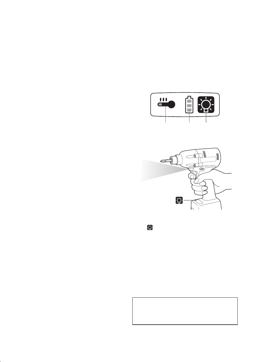
Control Panel
-
(3) (2) (1)
(1) LED light
-
Before the use of LED light, always pull the
power switch once.
Press the LED light on button.
The light illuminates with very low current, and
it does not adversely affect the performance of
the tool during use or its battery capacity.
CAUTION:
• The built-in LED light is designed to illu
minate the small work area temporarily.
• Do not use it as a substitute for a regu
lar flashlight, since it does not have
enough brightness.
• LED light turns off when the tool has
not been used for 5 minutes.
Caution : DO NOT STARE INTO BEAM.
Use of controls or adjustments or performance
of procedures other than those specied herein
may result in hazardous radiation exposure.
-
-
-
7 -

(2) The battery indication lamp
• Use the battery indication lamp to check
how much power is left in the battery.
• Battery life varies slightly with ambient temperature and battery characteristics. The
lamp is designed to provide a rough indication of remaining battery life.
Battery indication lamp
Indicator Battery status
Fully charged
Approx. 40% or less
remaining
Approx. 20% or less
remaining (indicates need
to recharge battery)
The battery pack will need
Flashing
Flashing
to be charged soon.
No charge
The battery pack needs to
be charged.
(The tool’s automatic
power-off function will
activate at this stage.)
Automatic power-off function
• The automatic power-off function is designed
to prevent a loss of tightening torque due to
reduced battery voltage. Once it has been
activated, the tool will not operate until the battery pack has been charged (or replaced with
a fresh unit), even if the trigger is depressed.
NOTE:
• All 3 bars on the battery indication lamp
will flash when the automatic power-off
function is activated.
• When the battery indication lamp begins
flashing, the battery pack should be
charged (or replaced with a fresh unit)
immediately.
• Be sure to fully charge the battery pack
after activation of the automatic poweroff function. Failure to do so may prevent
the automatic power-off function from
being properly deactivated.
(3) Overheat warning lamp
Flashing
The overheating protection feature halts tool
operation to protect the battery pack in the
event of overheating. The overheat warning
lamp on the control panel ashes when this
feature is active.
• If the overheating protection feature activates,
allow the tool to cool thoroughly (at least 30
minutes). The tool is ready for use when the
overheat warning lamp goes out.
• Avoid using the tool in a way that causes the
overheating protection feature to activate
repeatedly.
Adjusting the maximum
tightening torque
If the tightening torque is too high, it can be
lowered by limiting the maximum generated oil
pressure with the relief valve.
1. Place the forward/reverse switch in the
locked position and remove the battery pack.
Using a narrow-bladed flathead screwdriver
or similar tool, remove the rubber stopper.
Battery indication lamp
Indicator
Flashing
-
8 -
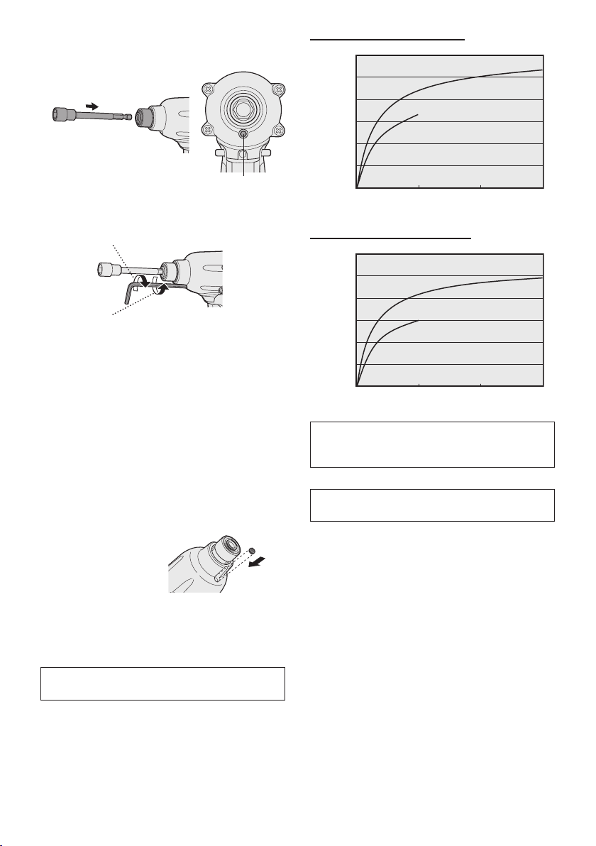
2. Attach a socket and rotate until the relief
0
0
0.5
1
1.5
2
2.5
3
5
10
15
20
25
30
N•m
M6
M8
0
0
0.5
1
1.5
2
2.5
3
5
10
15
20
25
30
N•m
M6
M8
valve is visible.
* View from front
Relief valve
Relief valve (default position)
(in-lbs)
(in-lbs)
(265.5)
(265.5)
Tightening torque
3. Adjust the relief valve with the hexagonal
head wrench.
Rotate clockwise to increase the tightening
*1
torque.
Rotate counterclockwise to decrease the
tightening torque.
CAUTION:
*1: Do not rotate the relief valve further
in the clockwise direction than its
default position. Doing so may impose
an excessive load that can damage
the tool. (The tool ships with the relief
valve rotated two turns to the left of its
maximum setting.)
• If the torque decreases, have the tool
inspected and repaired as necessary.
4. Reinsert the rubber stopper once you are
finished adjusting the valve.
CAUTION:
• Be sure to reinsert the rubber stopper.
Failure to do so may allow foreign matter inside the tool, damaging it.
Relationship between bolt
tightening time and torque
Tightening torque varies with bolt tightening
time as illustrated in the following figures.
(Figures show reference values. Actual performance varies with tightening conditions.)
Tightening time (Sec.)
Relief valve (minimum setting)
(in-lbs)
(in-lbs)
(265.5)
(265.5)
Tightening torque
Tightening time (Sec.)
Measurement conditions
• Temperature:
Room temperature (20°C/68°F)
Factors affecting bolt tightening
torque
Bolt tightening torque varies due to factors
described below.
1) Tightening time
Longer tightening time results in increased
tightening torque. Excessive tightening,
however, adds no value and reduces the
life of the tool.
2) Bolt
• Bolt diameter: Tightening torque gener-
ally increases with bolt diameter.
• Torque coefficient (indicated by the bolt
manufacturer), grade, length, etc.
3) Battery pack charge status
• Tightening torque decreases as the bat
tery is discharged.
-
9 -
-

-
10 -
• Tightening torque decreases rapidly as
the battery nears the end of its charge.
(The product’s automatic power-off func-
tion will engage once the battery’s charge
is exhausted.)
N·m
(kgf-cm)
Tightening torque
No. of bolts tightened per charge (Bolts)
Immediately
after charging
At end of
charge
4) Other
• Bit and socket condition: Material, amount
of play, etc.
• Use of a universal joint or socket adapter.
• User: Manner in which the tool is applied
to the bolt, strength with which the tool is
held, manner in which the tool’s switch is
engaged.
• Condition of object being tightened: Material, seating surface finish.
[Battery Pack]
For Appropriate Use of Bat-
tery Pack
Li-ion Battery Pack
• For optimum battery life, store the Li-ion battery pack following use without charging it.
• When charging the battery pack, confirm
that the terminals on the battery charger
are free of foreign substances such as dust
and water etc. Clean the terminals before
charging the battery pack if any foreign substances are found on the terminals.
The life of the battery pack terminals may be
affected by foreign substances such as dust
and water etc. during operation.
• When battery pack is not in use, keep it
away from other metal objects like: paper
clips, coins, keys, nails, screws, or other
small metal objects that can make a connection from one terminal to another.
Shorting the battery terminals together may
cause sparks, burns or a fire.
• When operating the battery pack, make sure
the work place is well ventilated.
• When the battery pack is removed from the
main body of the tool, replace the battery
pack cover immediately in order to prevent
dust or dirt from contaminating the battery
terminals and causing a short circuit.
Battery Pack Life
The rechargeable batteries have a limited life.
If the operation time becomes extremely short
after recharging, replace the battery pack with
a new one.
Battery Recycling
ATTENTION:
A Li-ion battery that is recyclable powers
the product you have purchased.
Please call 1-800-8-BATTERY for information on how to recycle this battery.
[Battery Charger]
Charging
Read the operating manual for Panasonic battery charger for the battery pack before charging.
Before charging the battery
Charge the battery at a temperature of 5°C
(41°F) to 40°C (104°F).
The battery pack cannot be charged at a temperature of less than 5°C (41°F). If the temperature
of the battery pack is less than 5°C (41°F), rst
remove the battery pack from the charger and
allow it to sit for an hour in a location where
the temperature is 5°C (41°F) or warmer. Then
charge the battery pack again.

VI
. MAINTENANCE
Use only a dry, soft cloth for wiping the unit.
Do not use a damp cloth, thinner, benzine, or
other volatile solvents for cleaning.
VII
. ACCESSORIES
Charger
• EY0L82
Battery pack
• EYFB30
• EYFB32
Protector for tool
• EYFA01-A (Blue)
• EYFA01-Y (Yellow)
• EYFA01-H (Gray)
• EYFA01-G (Green)
Protector for battery
• EYFA02-H (for EYFB30)
• EYFA03-H (for EYFB32)
Rubber stopper
• WEYFLC1AL367
-
11 -
 Loading...