

Panasonic EYFLA4AR, EYFLA5AR, EYFLA5QR, EYFLA6JR Service Manual
© Panasonic Corporation 2016
Unauthorized copying and distribution is a violation
of law.
Order Number PTD1601E08CE
Cordless Impact Driver / Cordless Impact Wrench
Model No. EYFLA4AR
EYFLA5AR
(Cordless Impact
Driver)
Model No. EYFLA5QR
EYFLA6JR
(Cordless Impact
Wrench)
Europe
TABLE OF CONTENTS
PAG E PAG E
1 Warning-------------------------------------------------------------- 2
2 Specifications ----------------------------------------------------- 2
3 Troubleshooting Guide ----------------------------------------- 3
4 Service Fixture and Adjustment----------------------------- 6
5 Disassembly and Assembly Instructions ---------------12
6 Measurements and Adjustments---------------------------21
7 Wiring Connection Diagram ---------------------------------24
8 Schematic Diagram ---------------------------------------------25
9 Exploded View and Replacement Parts List -----------26
2
1Warning
Caution:
• Pb free solder has a higher melting point that standard solder; Typicall the melting point is 50 - 70F (30 - 40C) higher. Please
use a soldering iron with temperature control and adjust it to 750 ± 20F (400 ± 10C). In case of using high temperature soldering iron, please be careful not to heat too long.
• Pb free solder will tend to splash when heated too high (about 1100F / 600C).
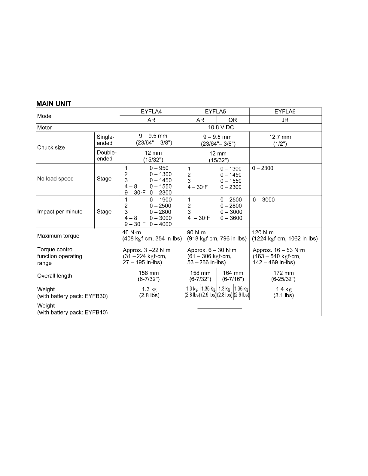
2 Specifications
3
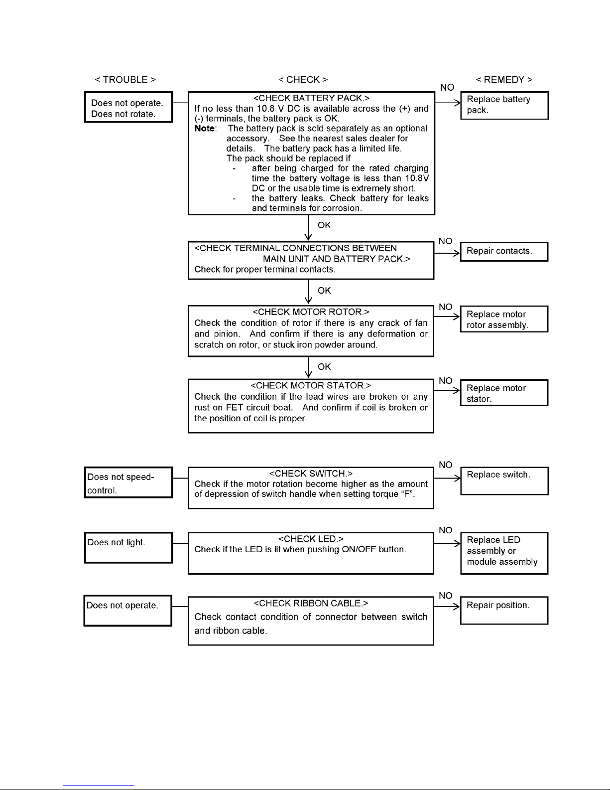
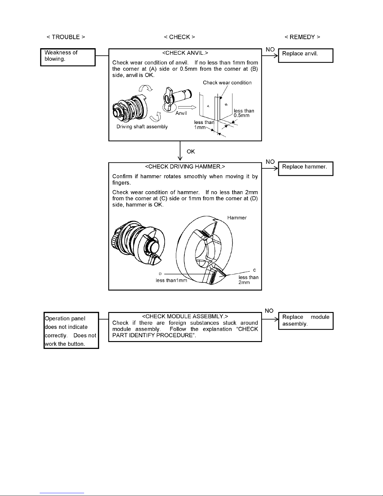
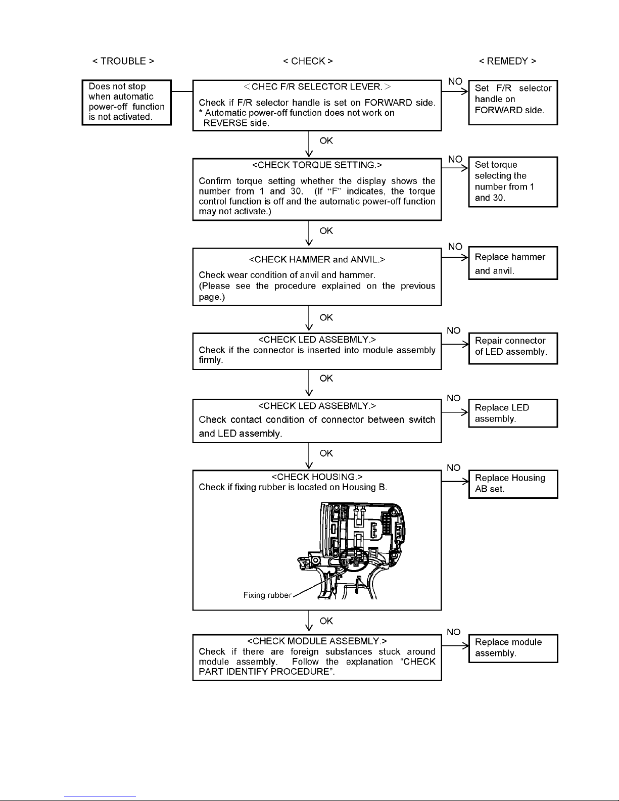
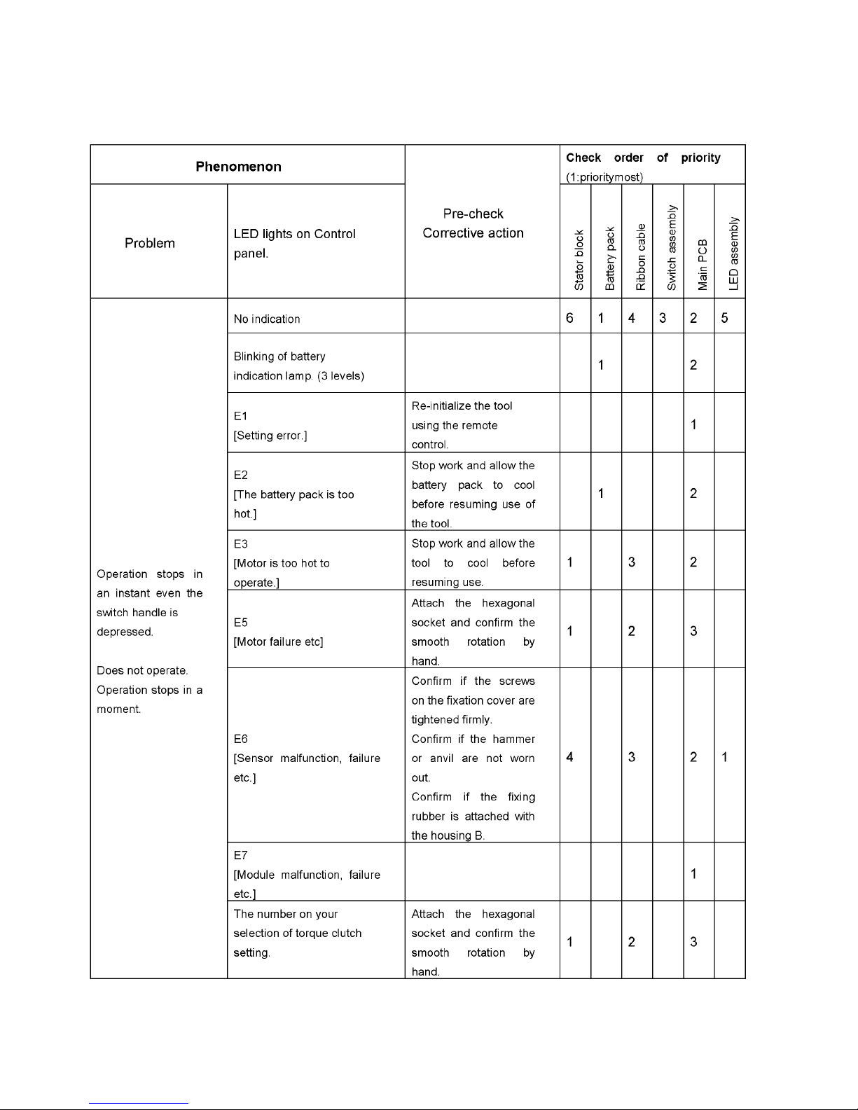
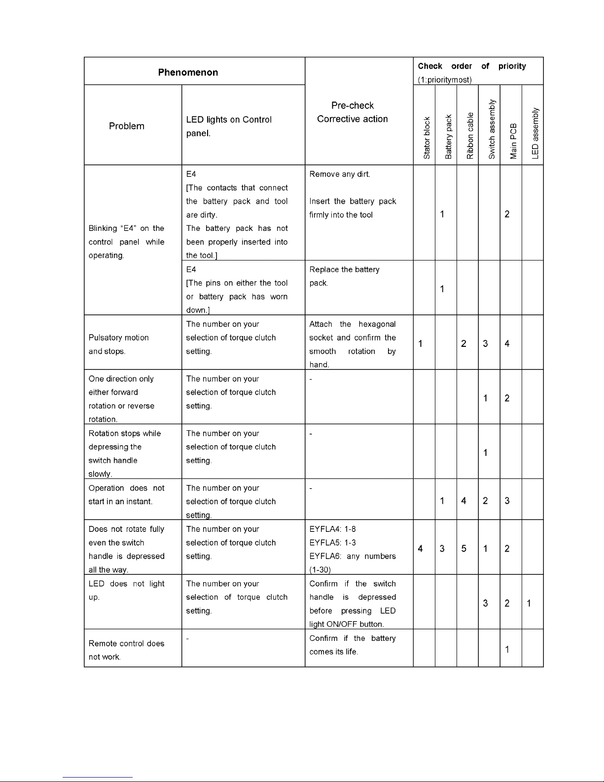
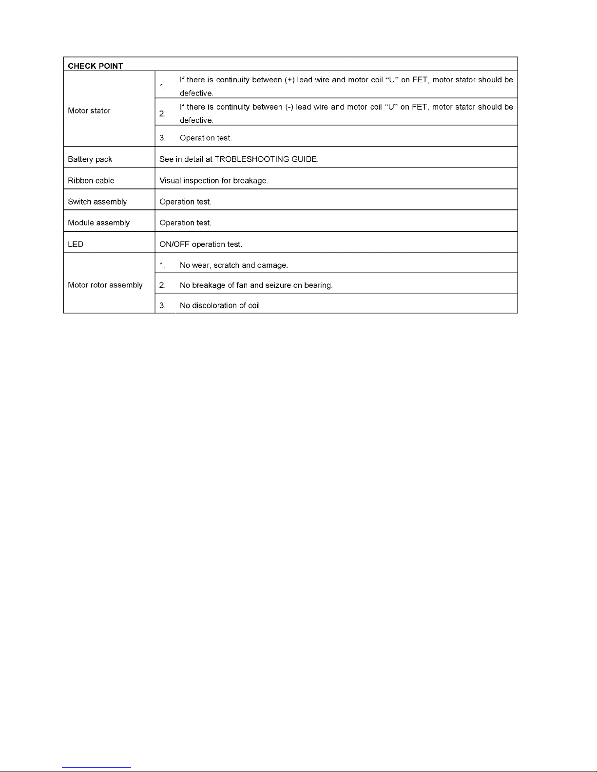
3 Troubleshooting Guide
4
5
6
4 Service Fixture and Adjustment
4.1. Check Parts Identify Procedure
7
8
9
4.2. Initializing and Setting
NOTE:
• This section explains how to revert all tool settings to their default values at the time of shipment from the factory.
• The error display will be turned off.
INITIALIZING ALL SETTINGS.
1. Set the tool to configuration mode.
(See the next procedure SETTINGS THE TOOL TO
CONFIGURATION MODE.)
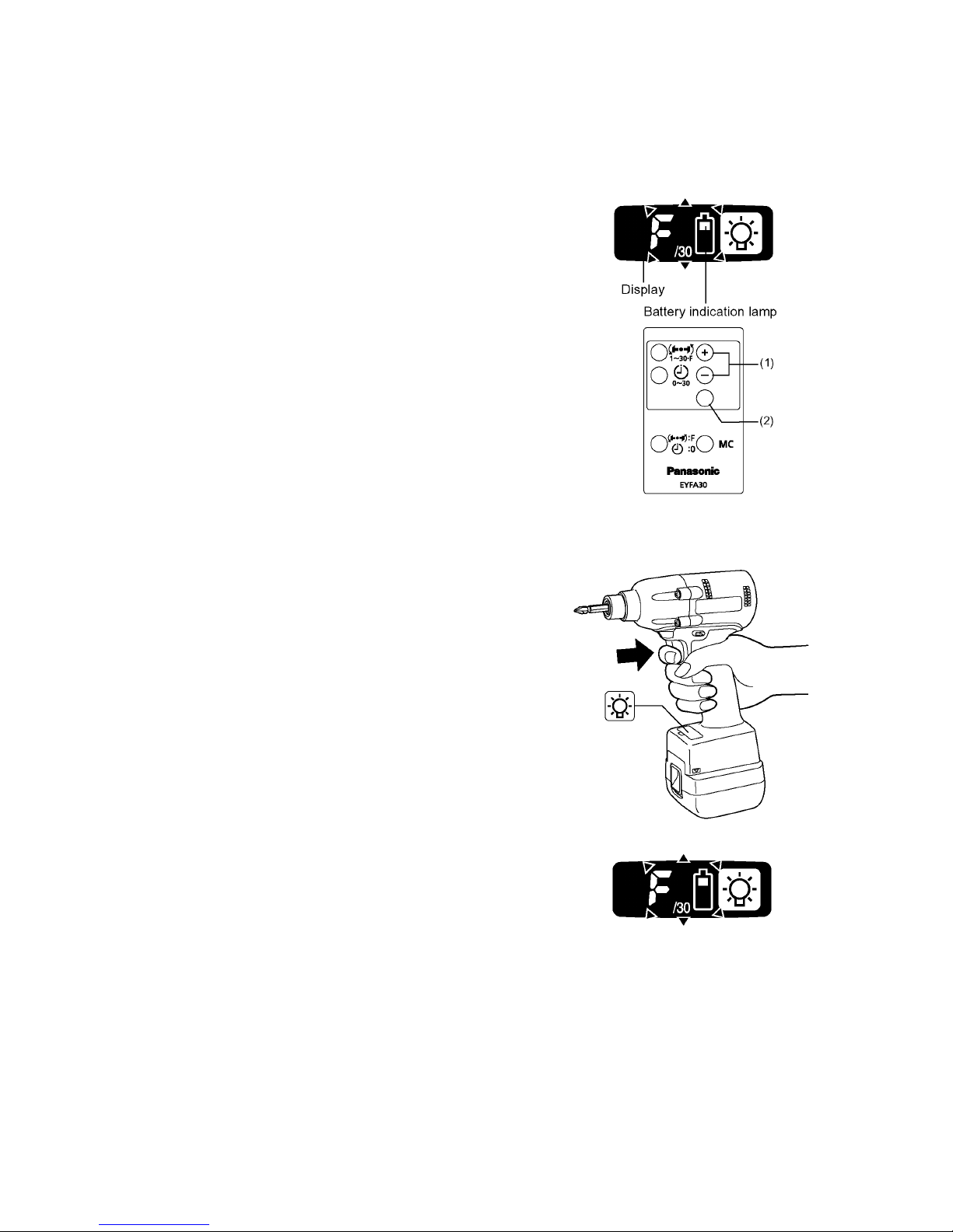
2. Press the format button.
a. The control panel will begin flashing.
DISPLAY: The letter “F” flashes on and off.
BATTERY INDICATION LAMP: The upper and lower
bars of the battery flash on and off.
3. Press the OK button to accept the selected setting.
a. The control panel will stop flashing and light up.
SETTINGS THE TOOL TO CONFIGURATION MODE.
1. Turn off the control panel.
If the control panel is on, remove and then reinsert the
battery pack.
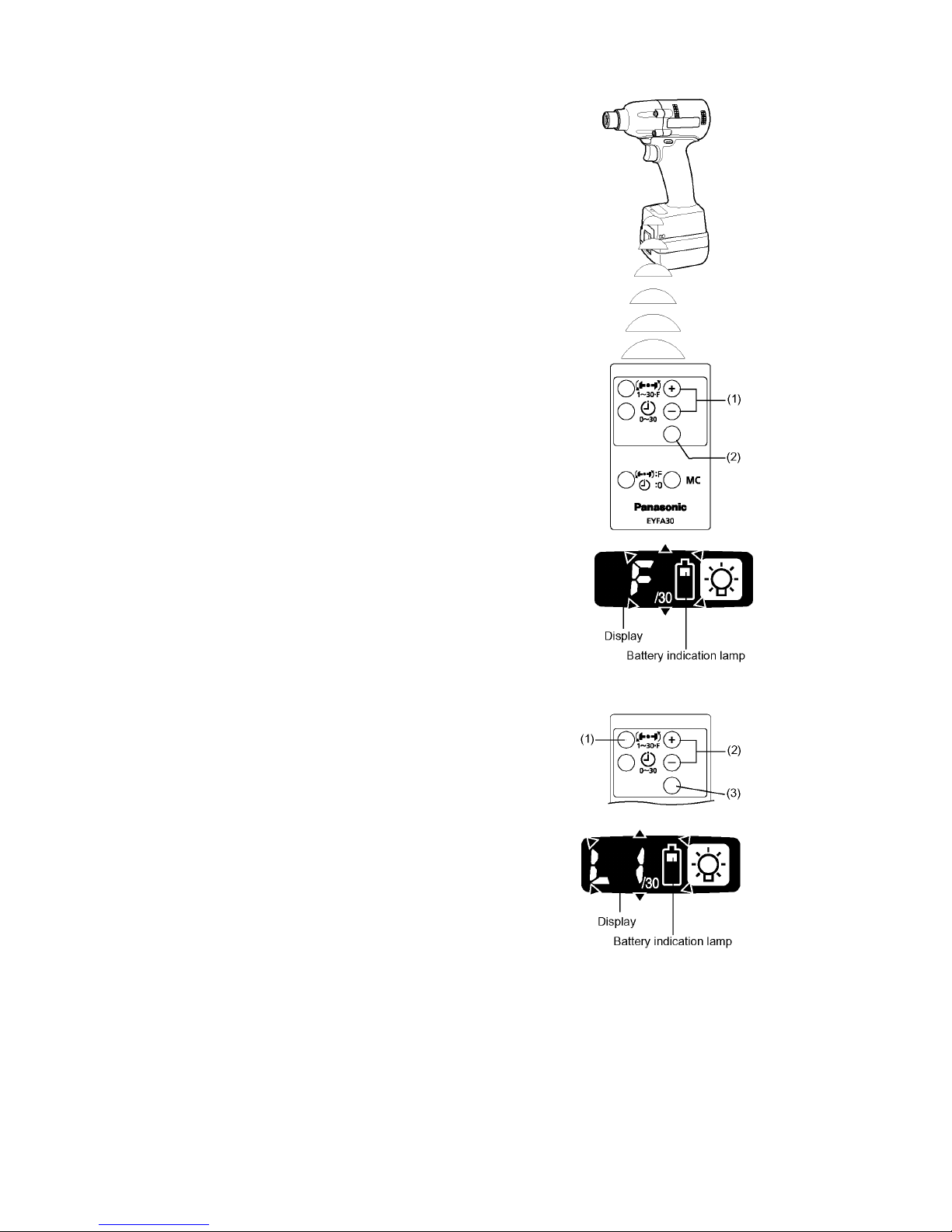
2. Engage the switch while pushing the button and then
release both the button and the switch.
a. After all the LED lamps have turned off, the control
panel will flash and change to configuration mode.
10
CONFIGURING THE TORQUE CLUTCH SETTING.
1. Press the (+) and (-) buttons to select the clutch setting
that is appropriate for the work being performed.
a. “F” indicates that the torque control function is off.
b. You can select from 30 torque clutch settings (1 to
30).
2. Press the OK button to accept the selected torque clutch
setting.
a. The control panel will stop flashing and light up.
NOTE:
You must press the OK button in order for the selected
setting to take effect.
SETTING THE SNUG POINT DETECTION LEVEL.
1. Press the torque setting mode button.
a. The snug point detection level setting value will be
displayed.
2. Press the (+) and (-) buttons to set the best snug point
detection level for the work you are performing.
3. Press the OK button to accept the number of torque
stages and the snug point detection level.
a. The tool’s panel will flash and then light up continu-
ously.
 Loading...