

Panasonic EY75A1LS2G, EY75A1X Owner's Manual
Cordles Impact Driver/Cordles Impact Wrench
Perceuse à impact sans fi l/Perceuse à impact sans fi l
Destornillador de impacto inalámbrico/Destornillador de impacto inalámbrico
Operating Instructions
Instructions d’utilisation
Manual de instrucciones
Model No: EY75A1/EY75A2
IMPORTANT
This manual contains safety information. Read manual completely before first using this product and save this
manual for future use.
IMPORTANT
Ce mode d’emploi contient des informations sur la sécurité. Lisez-le en entier avant d’utiliser le produit et
conservez-le pour référence.
IMPORTANTE
Este manual contiene información de seguridad. Lea completamente este manual antes de utilizar por primera
vez este producto, y guárdelo para poder consultarlo en el futuro.
Index/Index/Indice
English: Page 5 Français: Page 20 Español: Página 38
FUNCTIONAL DESCRIPTION
DESCRIPTION DES FONCTIONS
(A)′
DESCRIPCIÓN FUNCIONAL
(B)
(A)
(C)
(N)(M)
(O)
(P)
(J)
(I)
(D)
(Q)
(E)
(H)
(L)
(K)
(G)
10.8 V ─ 28.8 V
(F)
(S)
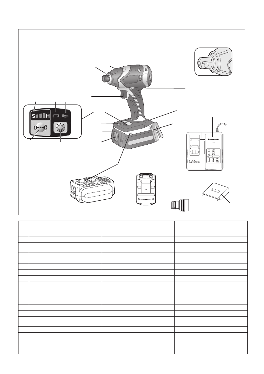
(A) 6.35 mm (1/4″) hex quick connect chuck
(A)′ Square drive (ball detent)
(B) Nose protector Protection du bec Protector del morro
(C) Forward/Reverse lever Levier d’inversion marche avant/
(D) Belt hook lock lever
(E) Belt hook Crochet de ceinture Gancho del cinturón
(F) Alignment marks Marques d’alignement Marcas de alineación
(G) Battery pack release button
(H) Battery pack Batterie autonome Batería
(I) LED light Lumière DEL Luz indicadora
(J) Control panel Panneau de commande Panel de control
(K) LED light ON/OFF button Bouton Marche/Arrêt de la lumière DEL Botón ON/OFF de luz LED
(L) Impact power mode button
(M) Impact power mode display
(N) Battery low warning lamp
(O) Overheat warning lamp (motor/battery) Témoin d’avertissement de surchauffe
(P) Variable speed control trigger Gâchette de commande de vitesse
(Q) Battery charger Chargeur de batterie Cargador de batería
(R) Pack cover Couvercle de la batterie autonome Cubierta de batería
(S) 6.35 mm (1/4") hex quick change
chuck (EY9HX110E)
Mandrin de connexion rapide hexagonal
de 6,35 mm (1/4
Mandrin
marche arrière
Levier de verrouillage du crochet de ceinture
Bouton de libération de batterie autonome
Bouton du mode de puissance de percussion
Affi chage du mode de puissance de percussion
Témoin d’avertissement de batterie basse
(moteur/batterie)
Mandrin hexagonal de 6,35 mm (1/4")
de changement rapide (EY9HX110E)
″
)
Mandril hexagonal de conexión rápida de
6,35 mm (1/4″)
Portabroca
Palanca de avance/marcha atrás
Palanca de bloqueo del gancho de cinturón
Botón de liberación de batería
Botón de modo de potencia de impacto
Indicación de modo de potencia de impacto
Luz de aviso de baja carga de batería
Luz de advertencia de sobrecalenta-
miento (motor/batería)
Disparador del control de velocidad variable
Portabroca de 6,35 mm (1/4”) cambio
rápido hexaonal (EY9HX110E)
(R)
-
2 -
Recommendations for use / Recommandations concernant l’utilisation / Recomendaciones par el uso
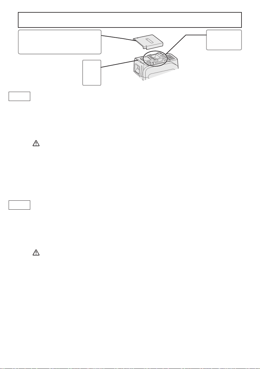
Pack cover
Couvercle de la batterie autonome
Cubierta de batería
GB
Be sure to use the Pack cover
• When the battery pack is not being used, store the battery in a way that foreign substances such as dust and
water etc. do not contaminate the terminals. Be sure to attach the battery pack cover to protect the battery
terminals.
• When charging the battery pack, confirm that the terminals on the battery charger are free of foreign
substances such as dust and water etc. Clean the terminals before charging the battery pack if any foreign
substances are found on the terminals.
The life of the battery pack terminals may be affected by foreign substances such as dust and water etc.
during operation.
CAUTION: To protect the motor or battery, be sure to note the following when carrying out this operation.
• If the motor or battery becomes hot, the protection function will be activated and the motor or battery will stop
operating.
The overheat warning lamp on the control panel illuminates or flashes when this feature is active.
For safe use
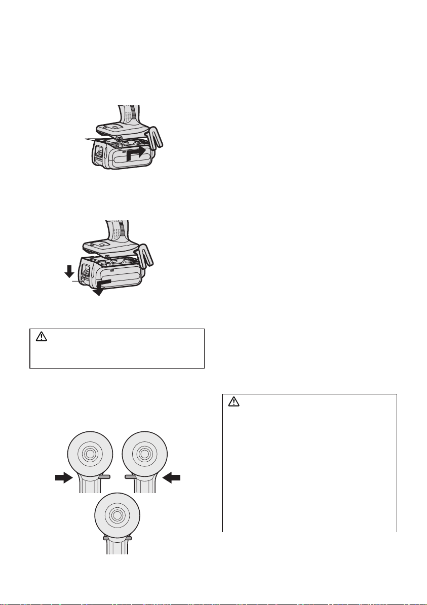
• The battery pack is designed to be installed by proceeding two steps for safety. Make sure the battery pack is
installed properly to the main body before use.
• If the battery pack is not inserted firmly when the switch is switched on, the overheat warning lamp and the
battery low warning lamp will flash to indicate that safe operation is not possible, and the bit will not rotate
normally. Insert the battery pack into the body of the tool until the red label disappears.
Veillez à utiliser le couvercle de la batterie autonome
F
• Lorsque le couvercle de la batterie autonome n’est pas utilisé, rangez la batterie de façon à ce qu’aucun corps
étranger comme de la poussière et de l’eau ne contamine les bornes. Veillez à fixer le couvercle de la batterie
autonome afin de protéger les bornes de la batterie.
• Lors de la charge de la batterie autonome, assurez-vous que les bornes du chargeur de batterie sont libres de
tout corps étranger comme de la poussière et de l’eau, etc. Nettoyez les bornes avant de charger la batterie
autonome si des corps étrangers se trouvent sur les bornes.
La durée de vie des bornes de la batterie autonome peut être affectée par des corps étrangers comme de la
poussière et de l’eau, etc. pendant le fonctionnement.
MISE EN GARDE: Pour protéger le moteur ou la batterie, veillez à bien noter les points suivants lorsque
• Si le moteur ou la batterie deviennent chauds, la fonction de protection sera activée et le moteur ou la batterie
cesseront de fonctionner. Le témoin d'avertissement de surchauffe s'allume ou clignote sur le panneau de
commande lorsque cette caractéristique est active.
Pour un usage sans risque
• La batterie est conçue pour être installée en procédant en deux étapes pour des raisons de sécurité. Assurezvous que la batterie est mise en place correctement avant d'utiliser l'outil.
• Lorsque la batterie autonome n'est pas fermement insérée, le té moin d'avertissement de surchauffe et le témoin
d’avertissement de batterie basse clignotent et la machine ne fait pas tourner la mèche comme habituellement
pour nous signaler que la machine ne fonctionne pas en toute sécurité même si un interrupteur a été enclenché.
Insérez la batterie autonome dans le corps de l'outil jusqu'à ce que l'indicateur rouge disparaisse.
Terminals
Bornes
Terminales
label
rouge
rojo
vous effectuez cette opération.
-
3 -

Asegúrese de utilizar la cubierta de la caja de batería
E
• Cuando no utilice la caja de batería, guarde la batería de tal forma que las materias extrañas tales como polvo
y agua, etc. ensucien los terminales. Asegúrese de colocar la cubierta de la caja de batería de tal forma de
proteger los terminales de la batería.
• Cuando cargue la caja de batería, confirme que los terminales en el cargador de batería estén libres de
materias extrañas tales como polvo y agua, etc. Limpie los terminales antes de cargar la caja de batería si hay
materias extrañas en los terminales.
La vida de los terminales de la caja de batería puede verse afectada por materias extrañas tales como polo y
agua, etc. durante su funcionamiento.
PRECAUCIÓN: Para proteger el motor o la batería, asegúrese de observar lo siguiente cuando efectúe
• Si el motor o la batería se calienta, se activará la función de protección y el motor o la batería dejará de
funcionar. La lámpara de advertencia de sobrecalentamiento en el panel de control se ilumina o destella
cuando esta característica está activada.
esta operación.
Para un uso más seguro
• La batería está diseñada para instalarse siguiendo dos pasos por motivos de seguridad.
Compruebe que la batería está instalada correctamente en el cuerpo principal antes de utilizar la herramienta.
• Si la batería no ha quedado bien introducida, la luz de advertencia de sobrecalentamiento y la luz de aviso de
baja carga de batería parpadearán, y la broca no girará del modo habitual para alertar al operario de que la
máquina no funcionará de manera segura si se acciona algún interruptor. Introduzca la batería en el cuerpo de
la herramienta hasta que el indicador rojo desaparezca.
-
4 -

This tool, as a complete unit with a battery pack,
t
r
r
satisfies appropriate IP Degrees of Protection
based on the IEC regulations.
Definition of IP code
IP5X: Ingress of dust is not totally prevented,
but dust shall not penetrate in a quantity to
interfere with satisfactory operation of the tool
or to impair safety (In case that the talcum
powder under 75 μm intrudes inside the tool).
IPX6: Water projected in powerful jets agains
the tool from any direction shall have no
harmful effects (In case that, with a nozzle
of 12.5 mm inner diameter, approximately
100 L/min of normal temperature water is
injected to the tool for 3 minutes from 3 mete
distance).
LIMITED WARRANTY
The rating of IP56 qualifies this tool for the
minimum impact of water or dust, but not fo
the assurance of performance in such conditions. See Safety and Operating Instructions
for further details for proper operation.
I. GENERAL
SAFETY RULES
WARNING! Read all instructions
Failure to follow all instructions listed
below may result in electric shock, fire
and/or serious injury. The term “power
tool” in all of the warnings listed below
refers to your mains operated (corded)
power tool and battery operated
(cordless) power tool.
SAVE THESE INSTRUCTIONS
Work Area Safety
1) Keep work area clean and well lit.
Cluttered or dark areas invite accidents.
2)
Do not operate power tools in explosive
atmospheres, such as in the presence
of flammable liquids, gases or dust.
Power tools create sparks which may
ignite the dust or fumes.
3) Keep children and bystanders away
while operating a power tool.
Distractions can cause you to lose control.
Electrical Safety
1) Power tool plugs must match the
outlet. Never modify the plug in any
way. Do not use any adapter plugs
with earthed (grounded) power tools.
Unmodified plugs and matching outlets
will reduce risk of electric shock.
2) Avoid body contact with earthed or
grounded surfaces such as pipes,
radiators, ranges and refrigerators.
There is an increased risk of electric shock
if your body is earthed or grounded.
3) Do not expose power tools to rain or
wet conditions.
Water entering a power tool will increase
the risk of electric shock.
4) Do not abuse the cord. Never use
the cord for carrying, pulling or
unplugging the power tool. Keep
cord away from heat, oil, sharp edges
or moving parts.
Damaged or entangled cords increase
the risk of electric shock.
5)
When operating a power tool outdoors,
use an extension cord suitable for
outdoor use.
Use of a cord suitable for outdoor use
reduces the risk of electric shock.
6)
If operating a power tool in a damp
location is unavoidable, use a residual
current device (RC D) protected
supply.
Use of RCD reduces the risk of
electrical shock.
Personal Safety
1)
Stay alert, watch what you are doing
and use common sense when operating
a power tool. Do not use a power tool
while you are tired or under the influence
of drugs, alcohol or medication.
A moment of inattention while operating
power tools may result in personal injury .
2) Use safety equipment. Always wear
eye protection.
Safety equipment such as dust mask,
non-skid safety shoes, hard hat, or
hearing protection used for appropriate
conditions will reduce personal injuries.
3) Avoid accidental starting. Ensure the
switch is in the off position before
plugging in.
Carrying power tools with your finger on
the switch or plugging in the power tools
that have the switch on invites accidents.
-
5 -

4) Remove any adjusting key or wrench
before turning the power tool on.
A wrench or a key left attached to a
rotating part of the power tool may result
in personal injury.
5) Do not overreach. Keep proper
footing and balance at all times.
This enables better control of the power
tool in unexpected situations.
6) Dress properly. Do not wear loose
clothing or jewellery. Keep your
hair, clothing and gloves away from
moving parts.
Loose clothes, jewellery or long hair can
be caught in moving parts.
7) If devices are provided for the
connection of dust extraction and
collection facilities, ensure these are
connected and properly used.
Use of these devices can reduce dust
related hazards.
Power Tool Use and Care
1)
Do not force the power tool. Use the
correct power tool for your application.
The correct power tool will do the job
better and safer at the rate for which it
was designed.
2) Do not use the power tool if the
switch does not turn it on and off.
Any power tool that cannot be controlled
with the switch is dangerous and must
be repaired.
3) Disconnect the plug from the power
source and/or the battery pack from
the power tool before making any
adjustments, changing accessories,
or storing power tools.
Such preventive safety measures
reduce the risk of starting the power tool
accidentally.
4)
Store idle power tools out of the reach
of children and do not allow persons
unfamiliar with the power tool or these
instructions to operate the power tool.
Power tools are dangerous in the hands
of untrained users.
5) Maintain power tools. Check for
misalignment or binding of moving
parts, breakage of parts and any other
condition that may affect the power
tools operation. If damaged, have the
power tool repaired before use.
Many accidents are caused by poorly
maintained power tools.
6) Keep cutting tools sharp and clean.
Properly maintained cutting tools with
sharp cutting edges are less likely to
bind and are easier to control.
7) Use the power tool, accessories
and tool bits etc. in accordance with
these instructions and in the manner
intended for the particular type of
power tool, taking into account the
working conditions and the work to
be performed.
Use of the power tool for operations
different from those intended could
result in a hazardous situation.
Battery Tool Use and Care
1) Ensure the switch is in the off position
before inserting battery pack.
Inserting battery pack into power tools
that have the switch on invites accidents.
2) Recharge only with the charger
specified by the manufacturer.
A charger that is suitable for one type
of battery pack may create a risk of fire
when used with another battery pack.
3) Use power tools only with specifically
designated battery packs.
Use of any other battery packs may
create a risk of injury and fire.
4)
When battery pack is not in use, keep it
away from other metal objects like paper
clips, coins, keys, nails, screws, or other
small metal objects that can make a
connection from one terminal to another.
Shorting the battery terminals together
may cause burns, or a fire.
5) Under abusive conditions, liquid may
be ejected from battery; avoid contact.
If contact accidentally occurs, flush
with water. If liquid contacts eyes,
additionally seek medical help.
Liquid ejected from the battery may
cause irritation or burns.
Service
1) Have your power tool serviced by a
qualified repair person using only
identical replacement parts.
This will ensure that the safety of power
tool is maintained.
-
6 -

II. SPECIFIC
SAFETY RULES
1) Wear ear protection. Exposure to noise
can cause hearing loss.
2)
Be aware that this tool is always in an
operating condition, since it does not have
to be plugged into an electrical outlet.
3)
Hold power tools by insulated grip-
ping sur faces when performing an
operation where the cutting tool may
contact hid den wiring.
Contact with a “live” wire will make ex-
posed metal parts of the tool “live” and
shock the operator.
4) If the bit becomes jammed, immediately
turn the trigger switch off to prevent an
overload which can damage the battery
pack or motor. Use reverse motion to
loosen jammed bits.
5) Do NOT operate the Forward/Reverse
lever when the trigger switch is on.
The battery will discharge rapidly and
damage to the unit may occur.
6) When storing or carrying the tool, set
the Forward/Reverse lever to the center
position (switch lock).
7) Do not strain the tool by holding the
speed control trigger halfway (speed
control mode) so that the motor stops.
The protection circuit will activate and
may prevent speed control operation. If
this happens, release the speed control
trigger and squeeze again for normal
operation.
8) Be careful not to get dust inside the
chuck.
9) Do not touch the rotating parts to avoid
injury.
10)
Do not use the tool continuously for a long
period of time. Stop using the tool from time
to time to avoid temperature rise and heat
overload of the motor.
11) Do not drop the tool.
Symbol Meaning
V Volts
Direct current
n
0
No load speed
… min
Ah
Electrical capacity of battery pack
To reduce the risk of injury user
per minutes
must read and understand
instruction manual.
Revolutions or reciprocations
-1
WARNING!
Some dust created by power sanding, sawing,
grinding, drilling, and other construction
activities contains chemicals known to the
State of California to cause cancer, birth
defects or other reproductive harm. Some
examples of these chemicals are:
• Lead from lead-based paints
• Crystalline silica from bricks and
cement and other masonry products
• Arsenic and chromium from chemicallytreated lumber.
To reduce your exposure to these
chemicals: work in a well ventilated area,
and work with approved safety equipment,
such as dust masks that are specially
designed to filter out microscopic particles.
III.
FOR BATTERY CHARGER
& BATTERY PACK
Important Safety Instructions
1) SAVE THESE INSTRUCTIONS -This
manual contains important safety and
operating instructions for battery charger.
2) Before using battery charger, read all
instructions and cautionary markings
on battery charger, battery pack, and
product using battery pack.
3) CAUTION -To reduce the risk of injury,
charge only Panasonic Battery Pack as
shown in last page.
Other types of batteries may burst
causing personal injury and damage.
4) Do not expose charger and battery pack
to rain or snow.
5) To reduce risk of damaging the electric
plug and cord, pull by plug rather than
cord when disconnecting charger.
6)
Make sure cord is located so that it
will not be stepped on, tripped over, or
otherwise subjected to damage or stress.
7) An extension cord should not be used
-
7 -

unless absolutely necessary.
Use of improper extension cord could
result in a risk of fire and electric shock.
If extension cord must be used, make
sure that:
a. pins on plug of extension cord are
the same number, size and shape as
those of plug on charger.
b. extension cord is properly wired and
in good electrical condition.
c. wire size is large enough for ampere
rating of charger as specified below.
RECOMMENDED MINIMUM AWG SIZE OF
AC Input Rating. Amperes
Equal to or
greater than
0 2 18 18 18 16
EXTENSION CORDS FOR
BATTERY CHARGERS
But less
than
AWG Size of Cord
Length of Cord,
Feet
25 50 100 150
8) Do not operate charger with damaged
cord or plug-replace them immediately.
9) Do not operate charger if it has received
a sharp blow, been dropped, or otherwise damaged in any way; take it to a
qualified service personnel.
10
) Do not disassemble charger; take it
to a qualified service personnel when
service or repair is required. Incorrect
reassembly may result in a risk of
electric shock or fire.
11) To reduce the risk of electric shock,
unplug charger from outlet before
attempting any maintenance or cleaning.
12)
The charger and battery pack are
specifically designed to work together. Do
not attempt to charge any other cordless
tool or battery pack with this charger.
13) Do not attempt to charge the battery
pack with any other charger.
14) Do not attempt to disassemble the
battery pack housing.
15) Do not store the tool and battery pack
in locations where the temperature
may reach or exceed 50°C (122°F)
(such as a metal tool shed, or a car
in the summer), which can lead to
deterioration of the storage battery.
16) Do not charge battery pack when the
temperature is BELOW 0°C (32°F)
or ABOVE 40°C (104°F). This is very
important in order to maintain optimal
condition of the battery pack.
17) Do not incinerate the battery pack. It
can explode in a fire.
18) Avoid dangerous environment. Do not
use charger in damp or wet locations.
19) The charger is designed to operate on
standard household electrical power
only. Do not attempt to use it on any
other voltage!
20) Do not abuse cord. Never carry charger
by cord or yank it to disconnect from
outlet. Keep cord away from heat, oil
and sharp edges.
21) Charge the battery pack in a well
ventilated place, do not cover the
charger and battery pack with a cloth,
etc., while charging.
22) Use of an attachment not recommended
may result in a risk of fire, electric
shock, or personal injury.
23) Do not short the battery pack. A battery
short can cause a large current flow,
over heating and create the risk of fire
or personal injury.
24) NOTE: If the supply cord of this
appliance is damaged, it must only be
replaced by a repair shop authorized
by the manufacturer, because special
purpose tools are required.
25) TO REDUCE THE RISK OF ELECTRIC
SHOCK, THIS APPLIANCE HAS A
POLARIZED PLUG (ONE BLADE IS
WIDER THAN THE OTHER).
This plug will fit in a polarized outlet only
one way. If the plug does not fit fully in
the outlet, reverse the plug. If it still does
not fit, contact a qualified electrician to
install the proper outlet. Do not change
the plug in any way.
-
8 -
WARNING:
• Do not use other than the Panasonic battery packs that are designed for use with
this rechargeable tool.
• Panasonic is not responsible for any damage or accident caused by the use of the
recycled battery pack and the counterfeit
battery pack.
• Do not dispose of the battery pack in a
fire, or expose it to excessive heat.
Do not drive the likes of nails into the battery
•
pack, subject it to shocks, dismantle it, or
attempt to modify it.
• Do not allow metal objects to touch the
battery pack terminals.
• Do not carry or store the battery pack
in the same container as nails or similar
metal objects.
• Do not charge the battery pack in a
high-temperature location, such as next
to a fire or in direct sunlight. Otherwise,
the battery may overheat, catch fire, or
explode.
• Never use other than the dedicated charger to charge the battery pack. Otherwise,
the battery may leak, overheat, or
explode.
• After removing the battery pack from the
tool or the charger, always reattach the
pack cover. Otherwise, the battery contacts could be shorted, leading to a risk of
fire.
• When the Battery Pack Has Deteriorated,
Replace It with a New One.
Continued use of a damaged battery pack
may result in heat generation, ignition or
battery rupture.
IV. ASSEMBLY
Attaching or Removing Bit
NOTE:
•
When attaching or removing a bit, disconnect battery pack from tool or place the
switch in the center position (switch lock).
1. Hold the collar of quick connect chuck and
pull it out from the driver.
2. Insert the bit into the chuck. Release the
collar.
3. The collar will return to its original position
when it is released.
4.
Pull the bit to make sure it does not come out.
5. To remove the bit, pull out the collar in the
same way.
CAUTION:
• If the collar does not return to its origi-
nal position or the bit comes out when
pulled on, the bit has not been properly
attached. Make sure the bit is properly
attached before use.
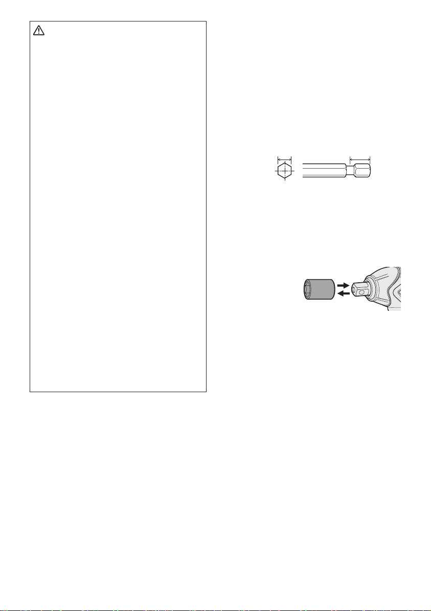
Use 6.35 mm (1/4") hexagonal bits.
To ensure proper securement of the bit,
use only hexagonal bits with 9.5 mm (3/8")
detent.
6.35 mm (1/4")
9.5 mm (3/8")
Attaching or Removing
Sock et
1. Attaching Socket
Attach the socket by sliding the female
detent on the bottom of the socket to the
square drive on the body.
Make sure the
socket is firmly
connected to
the body.
2. Removing Socket
Pull out the socket.
NOTE:
Attaching or Removing Original Options
and Sockets
Keep the body above freezing point
(0°C 32°F) when attach or detach
original options and sockets to the
square drive on the body. The cushion
rubber in the square drive to push up
the ball may get hard under freezing
point. This requires extra force in
detaching and attaching sockets.
-
9 -
Attaching or Removing
Bat tery Pack
1. To connect the battery pack:
Line up the alignment marks and attach
the battery pack.
• Slide the battery pack until it locks into
position.
Alignment
marks
2. To remove the battery pack:
Pull the button from the front to release the
battery pack.
Button
V. OPERATION
WARNING!
• Do not inhale any smoke emitted from the
tool or battery pack as it may be harmful.
CAUTION:
To prevent damage, do not operate
Forward/Reverse lever until the bit
comes to a complete stop.
Forward Rotation Switch
Operation
1. Push the lever for forward rotation.
2. Depress the trigger switch slightly to start
the tool slowly.
3. The speed increases with the amount of
depression of the trigger for efficient tightening of screws. The brake operates and
the bit stops immediately when the trigger
is released.
4. After use, set the lever to its center position (switch lock).
Reverse Rotation Switch
Operation
1.
Push the lever for reverse rotation. Check
direction of rotation before use.
2.
Depress the trigger switch slightly to start the
tool slowly.
3. After use, set the lever to its center position (switch lock).
CAUTION:
•
To eliminate excessive temperature
increase of the tool surface, do not operate the tool continuously using two or
more battery packs. Tool needs cool off
time before switching to another pack.
the
[Main Body]
Switch and Forward/Reverse
Lever Operation
Forward Reverse
Switch lock
-
How to Use the Belt Hook
WARNING!
• Be sure to attach the belt hook securely to
the main unit with the screw firmly fastened.
When the belt hook is not firmly attached to
the main unit, the hook may disconnect and
the main unit may fall.
This may result in an accident or injury.
• Periodically check screw for tightness. If
found to be loose, tighten firmly.
Be sure to attach the belt hook firmly and
•
securely onto a waist belt or other belt. Pay
attention that the unit does not slip off the
This may result in an accident or injury.
belt.
10 -
• When the main unit is held by the belt
hook, avoid jumping or running with it.
Doing so may cause the hook to slip and
the main unit may fall.
This may result in an accident or injury .
• When the belt hook is not used, be sure
to return it to the storing position. The belt
hook may catch on something.
This may result in an accident or injury.
When the unit is hooked onto the waist belt
•
by the belt hook, do not attach driver bits to
the unit. A sharp edge object, such as a drill
bit, may cause injury or an accident.
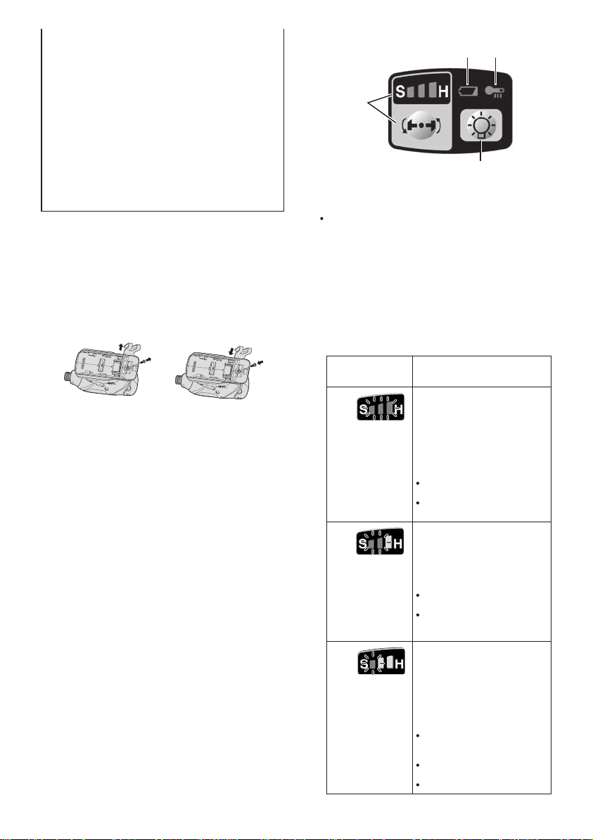
To Change the Belt Hook
Location Side
The belt hook can be attached to either side
of the unit.
1. Removing the hook
(1) Remove the nut.
(2) Draw out the hook.
2. Attaching the hook to the other side
(1) Insert the hook in the other side.
(2) Tighten the nut fully so that it securely
fastened.
V ariable Speed Control T rigger
To set the center of a hole, pull the trigger
slightly to start the bit rotation slowly.
The more the speed control trigger is
pulled, the higher the speed becomes.
CAUTION:
When operating the tool by pulling the
trigger, there may be a momentary lag
before rotation starts. This does not signal
a malfunction.
• This lag occurs as the tool’s circuitry
starts up when the trigger is pulled for
the first time after installing a new battery pack or after the tool has not been
used for at least 1 minute (or at least 5
minutes when the LED is on). Rotation
will start without any lag during second
and subsequent operations.
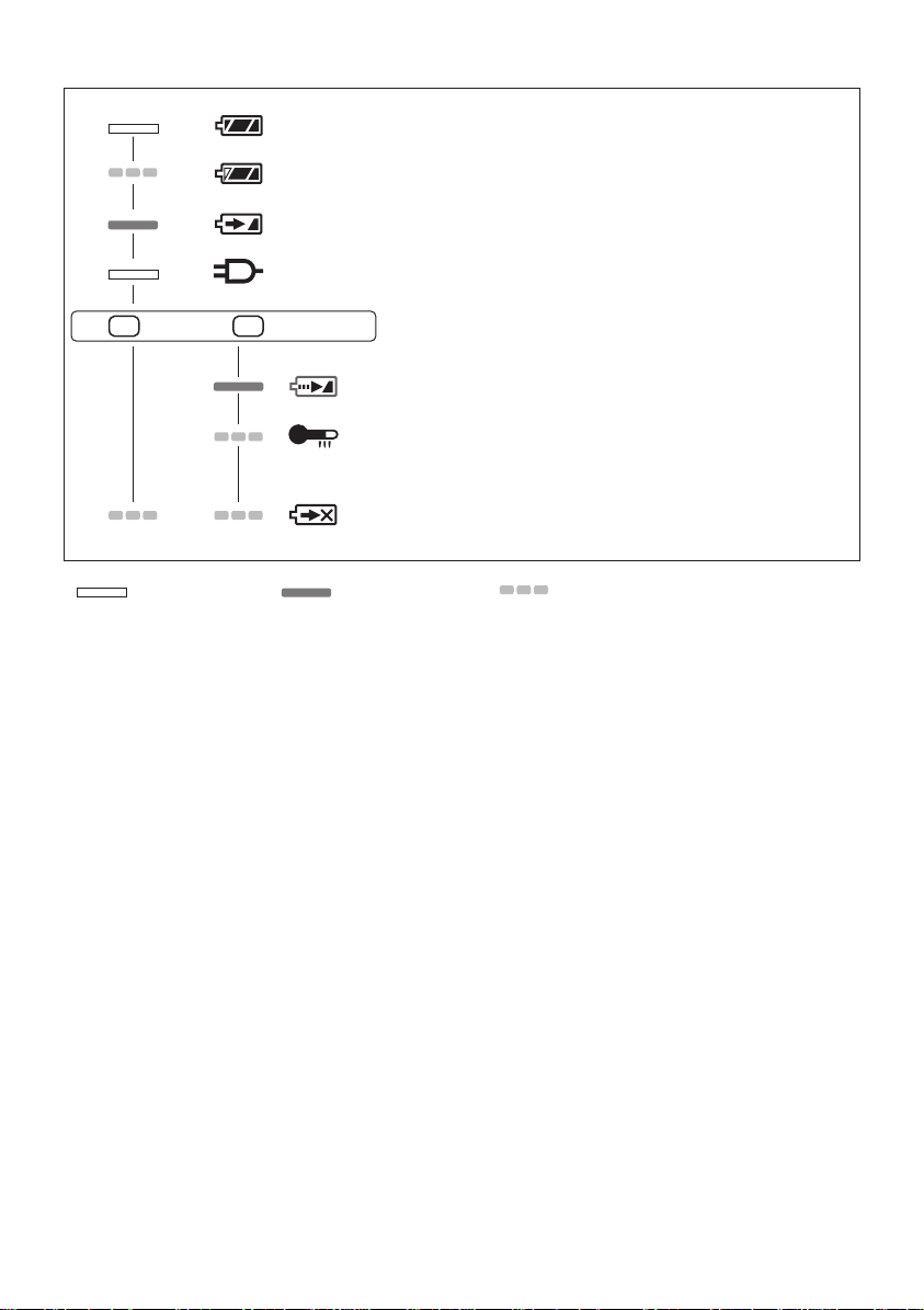
Control Panel
(4) (3)
(1)
(2)
(1) Impact Power Mode Select
Selecting the impact power among 3
modes (Soft, Medium, Hard).
Press the impact power mode button
to set it. The mode changes to hard,
medium, or soft each time the button is
pressed.
The driver is preset to “hard” impact mode
setting when shipped from the manufacturer.
Recommended work guideline table
Impact
Power mode
Display
H
0 – 2300 r.p.m./
0 – 2500 r.p.m.
and
0 – 3000 i.p.m./
0 – 3500 i.p.m.
M
0 – 1400 r.p.m.
and
0 – 2800 i.p.m.
S
0 – 1000 r.p.m.
and
0 – 2000 i.p.m.
Recommended Application
Jobs requiring a high level
of torque where there is
no possibility of the screw
breaking, its top shearing off,
or the bit coming loose. (This
setting provides maximum
torque.) Suitable applications
include:
Tightening M8 and larger
bolts
Tightening long screws
during interior finishing work
Jobs requiring limited torque
where there is a possibility of
the screw breaking or its top
shearing off. (This setting limits
torque.) Suitable applications
include:
Tightening bolts with
smaller diameters (M6)
Tightening metalwork
screws when installing
fixtures
Jobs requiring limited torque
where there is a possibility
of the screw breaking, its
top shearing off, or the bit
coming loose and damaging
a fi nished exterior surface.
(This setting limits torque.)
Suitable applications include:
Tightening bolts smaller
than M6 that may shear
easily
Tightening screws into
molded plastic
Installing gypsum wallboard
-
11 -
* i.p.m. = Impact per minute.
Avoid repeatedly depressing the switch
when the bolts and screws are securely
fastened.
Not doing so may cause a delay in
rotation starting, or the Impact Power
mode display to flash and prevent rotation
from starting for circuit protection.
(2) LED light
Pressing the but ton toggles the LED light on and off.
The light illuminates with
very low current, and it does
not adversely affect the per-
of the
formance
driver during
use or its battery capacity.
CAUTION:
• The built-in LED light is designed to illuminate the small work area temporarily.
•
Do not use it as a substitute for a regular
flashlight, since it does not have
enough brightness
This product has the built-in LED light.
This product is classified into “Class 1 LED
Product” to IEC (EN) 60825-1:2001.
Class 1 LED Product
Caution : DO NOT STARE INTO BEAM.
Use of controls or adjustments or performance
of procedures other than those specifi ed herein
may result in hazardous radiation exposure.
(3) Overheat warning lamp
.
• If the overheating protection feature
activates, allow the tool to cool
thoroughly (at least 30 minutes). The
tool is ready for use when the overheat
warning lamp goes out.
• Avoid using the tool in a way that
causes the overheating protection
feature to activate repeatedly.
• If the tool is operated continuously
under high-load conditions or if it is
used in hot-temperature conditions
(such as during summer), the
overheating protection feature may
activate frequently.
• If the tool is used in cold-temperature
conditions (such as during winter) or if
it is frequently stopped during use, the
overheating protection feature may not
activate.
• The performance of the EY9L42
deteriorates significantly at and below
10°C due to work conditions and other
factors.
• The ambient temperature range is
between 0°C (32°F) and 40°C (104°F).
If the battery pack is used when the
battery temperature is below 0°C
(32°F), the tool may fail to function
properly.
• Use the charger at temperatures
between 0°C and 40°C, and charge the
battery at a temperature similar to that
of the battery itself. (There should be no
more than a 15°C difference between
the temperatures of the battery and the
charging location.)
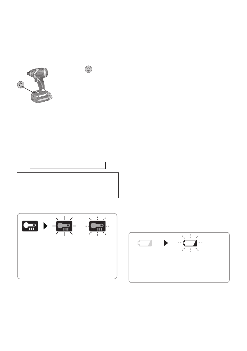
(4) Battery low warning lamp
Off
(normal
operation)
Illuminated:
Overheat
(motor)
Indicates operation has
been halted due to motor
or battery overheating.
Flashing:
Overheat
(battery)
To protect the motor or battery, be sure to
note the following when carrying out this
operation.
• If the motor or battery becomes hot, the
protection function will be activated and
the motor or battery will stop operating.
The overheat warning lamp on the
control panel illuminates or flashes
when this feature is active.
-
12 -
Off (normal
operation)
Flashing (No charge)
Battery protection
feature active
Excessive (complete) discharging of
lithium ion batteries shortens their service
life dramatically. The driver includes a
battery protection feature designed to
prevent excessive discharging of the
battery pack.
• The battery protection feature activates
immediately before the battery loses its

charge, causing the battery low warning
lamp to flash.
• If you notice the battery low warning
lamp flashing, charge the battery pack
immediately.
• If it is started with too little battery power
remaining, the tool may stop operating
without the battery low warning lamp
flashing first. This indicates that there is
too little battery power remaining to use
the tool, and the battery pack should be
charged before further use.
• If the tool is subject to a sudden load
during use that causes the motor to lock
up, the over current prevention sensor
may be triggered, and the impact power
select display may flash. The lamp will
stop flashing once you address the
cause of the motor’s locking up and
cycle the trigger.
Recommended Grip
Use the grip to hold and operate the driver
with one hand. If the job requires additional
force, you can push against the rear end of
the driver with your other hand.
[Battery Pack]
For Appropriate Use of Bat-
tery Pack
Li-ion Battery Pack
•
For optimum battery life, store the Li-ion battery pack following use without charging it.
• When charging the battery pack, confirm
that the terminals on the battery charger
are free of foreign substances such as
dust and water etc. Clean the terminals
before charging the battery pack if any
foreign substances are found on the terminals.
The life of the battery pack terminals may
be affected by foreign substances such as
dust and water etc. during operation.
• When battery pack is not in use, keep it
away from other metal objects like: paper
clips, coins, keys, nails, screws, or other
small metal objects that can make a connection from one terminal to another.
Shorting the battery terminals together
may cause sparks, burns or a fire.
• When operating the battery pack, make
sure the work place is well ventilated.
• When the battery pack is removed from
the main body of the tool, replace the battery pack cover immediately in order to
prevent dust or dirt from contaminating the
battery terminals and causing a short circuit.
Battery Pack Life
The rechargeable batteries have a limited life. If the operation time becomes
extremely short after recharging, replace
the battery pack with a new one.
Battery Recycling
ATTENTION:
FOR Li-ion Battery Pack
A Li-ion battery that is recyclable powers the
product you have purchased. Please call
1-800-8-BATTERY for information on how to
recycle this battery.
[Battery Charger]
Charging
Cautions
• If the temperature of the battery pack
falls approximately below −10°C (14°F),
charging will automatically stop to prevent
degradation of the battery.
• The ambient temperature range is
between 0°C (32°F) and 40°C (104°F).
If the battery pack is used when the battery
temperature is below 0°C (32°F), the tool
may fail to function properly.
• Use the charger at temperatures between
0°C and 40°C, and charge the battery at
a temperature similar to that of the battery
itself. (There should be no more than a
15°C difference between the temperatures
of the battery and the charging location.)
• When charging a cool battery pack (below
0°C (32°F)) in a warm place, leave the
battery pack at the place and wait for more
than one hour to warm up the battery to
the level of the ambient temperature.
-
13 -
• Cool down the charger when charging
more than two battery packs consecutively.
• Do not insert your fingers into contact
hole, when holding charger or any other
occasions.
CAUTION:
To prevent the risk of fire or damage to
the battery charger.
• Do not use power source from an
engine generator.
• Do not cover vent holes on the
charger and the battery pack.
• Unplug the charger when not in use.
Li-ion Battery Pack
NOTE:
Your battery pack is not fully charged at
the time of purchase. Be sure to charge
the battery before use.
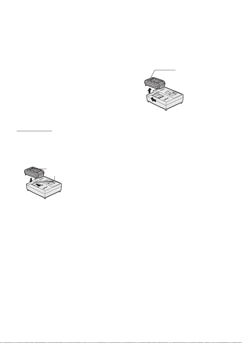
Battery charger
1. Plug the charger into the AC outlet.
2.
Insert the battery pack firmly into the charger.
1 Line up the alignment marks and place the
battery onto the dock on the charger.
2 Slide forward in the direction of the arrow.
Alignment marks
ing temperature.
Consult an authorized dealer if the charging
7.
lamp (green) does not turn off.
8. If a fully charged battery pack is inserted
into the charger again, the charging lamp
lights up. After several minutes, the charging lamp in green color will turn off.
9. Remove the battery pack while the battery
pack release button is held up.
Battery pack
release button
3.
During charging, the charging lamp will be lit.
When charging is completed, an internal
electronic switch will automatically be triggered to prevent overcharging.
• Charging will not start if the battery pack
is warm (for example, immediately after
heavy-duty operation).
The orange standby lamp will be flash-
ing until the battery cools down.
Charging will then begin automatically.
4. The charge lamp (green) will flash slowly
once the battery is approximately 80%
charged.
When charging is completed, the charging
5.
lamp in green color will turn off.
6. If the temperature of the batter pack is
0°C or less, charging takes longer to fully
charge the battery pack than the standard
charging time.
Even when the battery is fully charged, it
will have approximately 50% of the power
of a fully charged battery at normal operat-
-
14 -
LAMP INDICATIONS
Charging is completed. (Full charge.)
Battery is approximately 80% charged.
Now charging.
Charger is plugged into the AC outlet. Ready to charge.
(Green) (Orange)
Turn off Lit Flashing
Charging Status Lamp.
Left: green Right: orange will be displayed.
Battery pack is cool.
The battery pack is being charged slowly to reduce the load on the battery.
Battery pack is warm.
Charging will begin when temperature of battery pack drops. If the temperature of the
battery pack is -10° or less, the charging status lamp (orange) will also start flashing .
Charging will begin when the temperature of the battery pack goes up"
Charging is not possible. Clogged with dust or malfunction of the battery pack.
-
15 -
VI. MAINTENANCE
• Use only a dry, soft cloth for wiping the unit.
Do not use a damp cloth, thinner, benzine,
or other volatile solvents for cleaning.
• In the event that the inside of the tool or
battery pack is exposed to water, drain
and allow to dry as soon as possible.
Carefully remove any dust or iron filings
that collect inside the tool. If you experience any problems operating the tool,
consult with a repair shop.
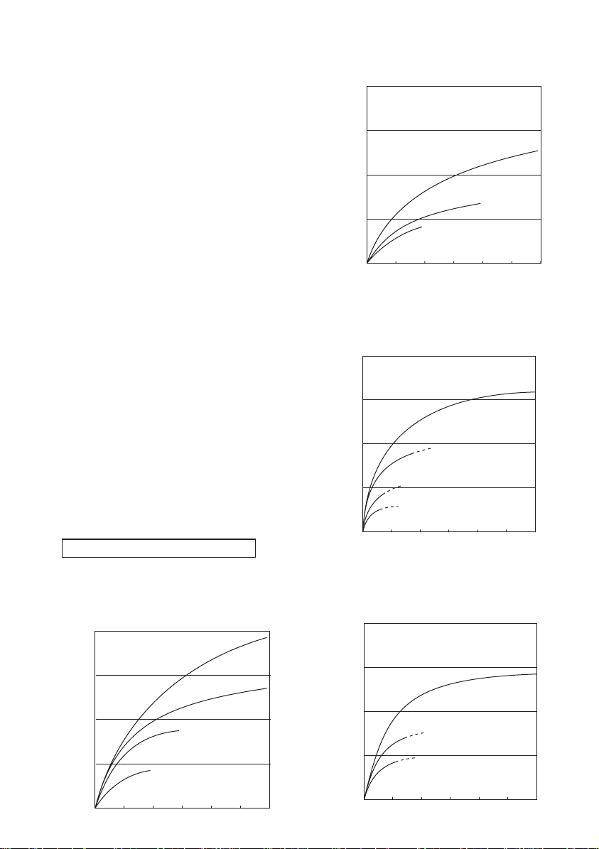
VII. TIGHTENING
TORQUE
The power required for tightening a bolt will
vary, according to bolt material and size, as
well as the material being bolted. Choose
the length of tightening time accordingly.
Reference values are provided below.
(They may vary according to tightening conditions.)
Factors Affecting Tightening Torque
The tightening torque is affected by a wide
variety of factors including the followings.
After tightening, always check the torque
with a torque wrench.
1) Voltage
When the battery pack becomes near-
ly discharged, the voltage decreases and
the tightening torque drops.
Bolt Tightening Conditions
EY75A1 14.4 V
M10 x 35 mm M12, M14, M16 x 45 mm
N s m
(kgf-cm)
196.0
(2000)
147.0
(1500)
98.0
(1000)
49.0
Tightening torque
(500)
M12
M10
Standard bolt
M16
M14
EY75A1 14.4 V
N s m
(kgf-cm)
196.0
(2000)
147.0
(1500)
(1000)
Tightening torque
(500)
M8, M10 x 35 mm. M12 x 45 mm
98.0
49.0
0.50.0 1.0 1.5 2.0 2.5 3.0
EY75A2 14.4 V
M10 x 35 mm M12, M14, M16 x 45 mm
N s m
(kgf-cm)
196.0
(2000)
147.0
(1500)
98.0
(1000)
49.0
Tightening torque
(500)
M12
M10
0.50.0 1.0 1.5 2.0 2.5 3.0
EY75A2 14.4 V
N s m
(kgf-cm)
196.0
(2000)
147.0
(1500)
98.0
(1000)
49.0
Tightening torque
(500)
M8, M10 x 35 mm. M12 x 45 mm
High tensile bolt
M12
M10
M8
Tightening time (Sec.)
Standard bolt
M16
M14
Tightening time (Sec.)
High tensile bolt
M12
M10
M8
0.50.0 1.0 1.5 2.0 2.5 3.0
Tightening time (Sec.)
-
16 -
0.50.0 1.0 1.5 2.0 2.5 3.0
Tightening time (Sec.)
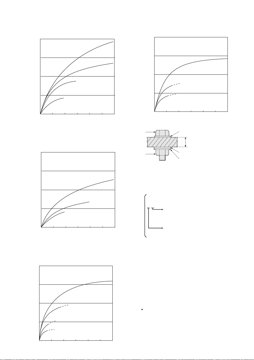
EY75A1 18 V
M10 x 35 mm M12, M14, M16 x 45 mm
N s m
(kgf-cm)
196.0
(2000)
147.0
(1500)
98.0
(1000)
49.0
Tightening torque
(500)
M10
M12
Standard bolt
M16
M14
EY75A2 18 V
N s m
(kgf-cm)
196.0
(2000)
147.0
(1500)
98.0
(1000)
49.0
Tightening torque
(500)
M8, M10 x 35 mm. M12 x 45 mm
High tensile bolt
M12
M10
M8
EY75A1 18 V
N s m
(kgf-cm)
196.0
(2000)
147.0
(1500)
98.0
(1000)
49.0
Tightening torque
(500)
EY75A2 18 V
M10 x 35 mm M12, M14, M16 x 45 mm
N s m
(kgf-cm)
196.0
(2000)
147.0
(1500)
98.0
(1000)
49.0
Tightening torque
(500)
M10
0.50.0 1.0 1.5 2.0 2.5 3.0
Tightening time (Sec.)
M8, M10 x 35 mm. M12 x 45 mm
High tensile bolt
M12
M10
M8
0.50.0 1.0 1.5 2.0 2.5 3.0
Tightening time (Sec.)
Standard bolt
M16
M14
M12
0.50.0 1.0 1.5 2.0 2.5 3.0
Tightening time (Sec.)
Bolt
Washer
Steel plate
thickness 10 mm (3/8")
Nut
Washer
Spring washer
Tightening conditions
• The following bolts are used.
Standard bolts: Strength type 4.8
High tensile type 12.9
Explanation of the strength type
4.8
Bolt yield point
(
80% of tensile strength)
32 kgf/mm
Bolt tensile strength
40 kgf/mm
2
(45000 psi)
2
(56000 psi)
2) Tightening time
Longer tightening time results in increased
tightening torque. Excessive tightening,
how ever, adds no value and reduces the
life of the tool.
3) Different bolt diameters
The size of the bolt diameter affects the
tight ening torque.
Generally, as the bolt diameter increases,
tightening torque rises.
4) Tightening conditions
Tightening torque will vary, even with the
same bolt, according to grade, length, and
torque coefficient (the fixed coefficient indicated by the manufacturer upon production).
0.50.0 1.0 1.5 2.0 2.5 3.0
Tightening time (Sec.)
-
17 -
 Loading...