

Panasonic EY7549X User Manual [en, es, fr]

Operating Instructions
Instructions d’utilisation
Manual de instrucciones
Multi-Impact & Drill Driver
Entraînement perceuse & percussions multiples
Pistola taladradora y múltiples impactos
Model No: EY7549
IMPORTANT
Before operating this unit, please read these instructions completely and save this manual for future use.
IMPORTANT
Lire entièrement les instructions suivantes avant de faire fonctionner l’appareil et conserver ce mode d’emploi
à des fins de consultation ultérieure.
IMPORTANTE
Antes de usar este aparato por primera vez, lea todas las instrucciones de este manual y guarde el manual
para poderlo consultar en el futuro.
Index/Index/Indice
English: Page .............................. 4
Français: Page ............................ 20
Español: Página ......................... 39
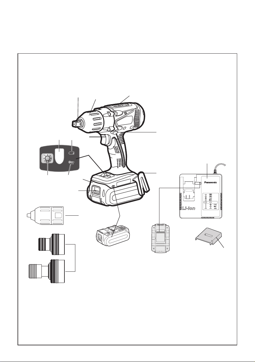
FUNCTIONAL DESCRIPTION
DESCRIPTION DES FONCTIONS
DESCRIPCIÓN FUNCIONAL
(K)(J)
(F)
(C)
(F)
(D)
(O)
(E)
10.8 V ─ 28.8 V
(P)
(A)
(B)
(N)
(M)(L)
(I)
(H)
(G)
(Q)
(R)
NOTE:
Either EY9HX110E or EY9HX111E is included in this kit.
REMARQUE :
EY9HX110E ou EY9HX111E est inclus dans ce kit
NOTA:
En este kit está incluido o EY9HX110E o EY9HX111E.
-
2 -

6.35 mm (1/4’’) hex quick connect chuck
Mandrin de connexion rapide hexagonal de 6,35 (1/4’’) mm
(A)
Mandril hexagonal de conexión rápida de 6,35
(1/4’’)
mm
Clutch handle
Poignée de l’embrayage
(B)
Mango de embrague
Mode Select Switch (Drill driver High/Low mode
with clutch function, Impact mode)
Sélecteur de mode (haute vitesse perceuse/
visseuse, basse vitesse perceuse/visseuse à
(C)
fonction d’embrayage, mode percussion)
Interruptor de selección de modo (Modo de
taladro atornillador alto/bajo con función de
embrague, modo de impacto)
Belt hook
Crochet de ceinture
(E)
Gancho del cinturón
Battery pack release button
Bouton de libération de batterie autonome
(G)
Botón de liberación de la batería
Control panel
Panneau de commande
(I)
Panel de controle
LED light on/off button
Bouton Marche/Arrêt de la lumière DEL
(K)
Botón ON/OFF de luz LED
Battery low warning lamp
Témoin d’avertissement de batterie basse
(M)
Luz de aviso de baja carga de batería
Forward/Reverse lever
Levier d’inversion marche avant-marche arrière
Palanca de avance/marcha atrás
(D)
Alignment marks
Marques d’alignement
(F)
Marcas de alineación
Battery pack
Batterie autonome
(H)
Batería
Overheat warning lamp (battery)
Témoin d’avertissement de surchauffe (batterie)
(J)
Luz de advertencia de sobrecalentamiento (batería)
LED light
Lumière DEL
(L)
Luz indicadora
Variable speed control trigger
Gâchette de commande de vitesse
(N)
Disparador del control de velocidad variable
Battery charger
Chargeur de batterie
(O)
Cargador de la batería
Keyless drill chuck
Mandrin de percage sans cle
(Q)
Portabrocas de apriete sin llave
-
3 -
Pack cover
Couvercle de la batterie autonome
(P)
Cubierta de batería
Quick change chuck
Mandrin à remplacement rapide
(R)
Portabrocas de cambio ràpido

This tool, as a complete unit with a
battery pack, satisfies appropriate IP
Degrees of Protection based on the IEC
regulations.
Definition of IP code
IP5X: Ingress of dust is not totally prevented, but dust shall not penetrate in
a quantity to interfere with satisfactory
operation of the tool or to impair safety
(In case that the talcum powder under
75 μm intrudes inside the tool).
IPX6: Water projected in powerful jets
against the tool from any direction shall
have no harmful effects (In case that,
with a nozzle of 12.5 mm inner diameter, approximately 100 L/min of normal
temperature water is injected to the tool
for 3 minutes from 3 meter distance).
LIMITED WARRANTY
The rating of IP56 qualifies this tool for
the minimum impact of water or dust,
but not for the assurance of performance in such conditions. See Safety
and Operating Instructions for further
details for proper operation.
I. GENERAL
SAFETY RULES
WARNING! Read all instructions
Failure to follow all instructions listed below
may result in electric shock, fi re and/or seri-
ous injury. The term “power tool” in all of the
warnings listed below refers to your mains
operated (corded) power tool and battery
operated (cordless) power tool.
SAVE THESE INSTRUCTIONS
Work Area Safety
1) Keep work area clean and well lit.
Cluttered or dark areas invite acci-
dents.
2) Do not operate power tools in
explosive atmospheres, such as
in the presence of flammable liquids, gases or dust.
Power tools create sparks which
may ignite the dust or fumes.
3) Keep children and bystanders
away while operating a power tool.
Distractions can cause you to lose
control.
Electrical Safety
1)
Power tool plugs must match the
outlet. Never modify the plug in any
way. Do not use any adapter plugs
with earthed (grounded) power tools.
Unmodified plugs and matching out-
lets will reduce risk of electric shock.
2) Avoid body contact with earthed or
grounded surfaces such as pipes,
radiators, ranges and refrigerators.
There is an increased risk of electric
shock if your body is earthed or grounded.
3) Do not expose power tools to
rain or wet conditions.
Water entering a power tool will in-
crease the risk of electric shock.
4) Do not abuse the cord. Never use
the cord for carrying, pulling or
unplugging the power tool. Keep
cord away from heat, oil, sharp
edges or moving parts.
Damaged or entangled cords in-
crease the risk of electric shock.
5) When operating a power tool
outdoors, use an extension cord
suitable for outdoor use.
Use of a cord suitable for outdoor
use reduces the risk of electric shock.
6) If operating a power tool in a
damp location is unavoidable, use
a residual current device (RCD)
protected supply.
Use of RCD reduces the risk of elec-
trical shock.
Personal Safety
1) Stay alert, watch what you are
doing and use common sense
when operating a power tool. Do
not use a power tool while you
are tired or under the influence of
drugs, alcohol or medication.
A moment of inattention while operating
power tools may result in personal injury.
2) Use safety equipment. Always
wear eye protection.
Safety equipment such as dust mask,
non-skid safety shoes, hard hat, or
hearing protection used for appropriate
conditions will reduce personal injuries.
3) Avoid accidental starting. Ensure
the switch is in the off position
before plugging in.
Carrying power tools with your fin-
ger on the switch or plugging in the
power tools that have the switch on
invites accidents.
-
4 -

4)
Remove any adjusting key or wrench
before turning the power tool on.
A wrench or a key left attached to a
rotating part of the power tool may
result in personal injury.
5) Do not overreach. Keep proper
footing and balance at all times.
This enables better control of the
power tool in unexpected situations.
6) Dress properly. Do not wear
loose clothing or jewellery. Keep
your hair, clothing and gloves
away from moving parts.
Loose clothes, jewellery or long hair
can be caught in moving parts.
7) If devices are provided for the
connection of dust extraction and
collection facilities, ensure these
are connected and properly used.
Use of these devices can reduce
dust related hazards.
Power Tool Use and Care
1) Do not force the power tool. Use
the correct power tool for your
application.
The correct power tool will do the
job better and safer at the rate for
which it was designed.
2) Do not use the power tool if the
switch does not turn it on and off.
Any power tool that cannot be con-
trolled with the switch is dangerous
and must be repaired.
Disconnect the plug from the power
3)
source and/or the battery pack from
the power tool before making any
adjustments, changing accessories, or storing power tools.
Such preventive safety measures
reduce the risk of starting the power
tool accidentally.
4) Store idle power tools out of
the reach of children and do not
allow persons unfamiliar with the
power tool or these instructions
to operate the power tool.
Power tools are dangerous in the
hands of untrained users.
5) Maintain power tools. Check for
misalignment or binding of moving parts, breakage of parts and
any other condition that may affect the power tools operation.
If damaged, have the power tool
repaired before use.
Many accidents are caused by poorly
maintained power tools.
Keep cutting tools sharp and clean.
6)
Properly maintained cutting tools with
sharp cutting edges are less likely to
bind and are easier to control.
7) Use the power tool, accessories
and tool bits etc. in accordance
with these instructions and in the
manner intended for the particular type of power tool, taking into
account the working conditions
and the work to be performed.
Use of the power tool for operations
different from those intended could
result in a hazardous situation.
Battery Tool Use and Care
Ensure the switch is in the off posi-
1)
tion before inserting battery pack.
Inserting battery pack into power
tools that have the switch on invites
accidents.
2) Recharge only with the charger
specified by the manufacturer.
A charger that is suitable for one
type of battery pack may create a
risk of fire when used with another
battery pack.
Use power tools only with specifi-
3)
cally designated battery packs.
Use of any other battery packs may
create a risk of injury and fire.
4)
When battery pack is not in use,
keep it away from other metal objects like paper clips, coins, keys,
nails, screws, or other small metal
objects that can make a connection from one terminal to another.
Shorting the battery terminals togeth-
er may cause burns, or a fire.
5) Under abusive conditions, liquid
may be ejected from battery;
avoid contact. If contact accidentally occurs, flush with water. If
liquid contacts eyes, additionally
seek medical help.
Liquid ejected from the battery may
cause irritation or burns.
Service
Have your power tool serviced by a
1)
qualified repair person using only
identical replacement parts.
This will ensure that the safety of
power tool is maintained.
-
5 -
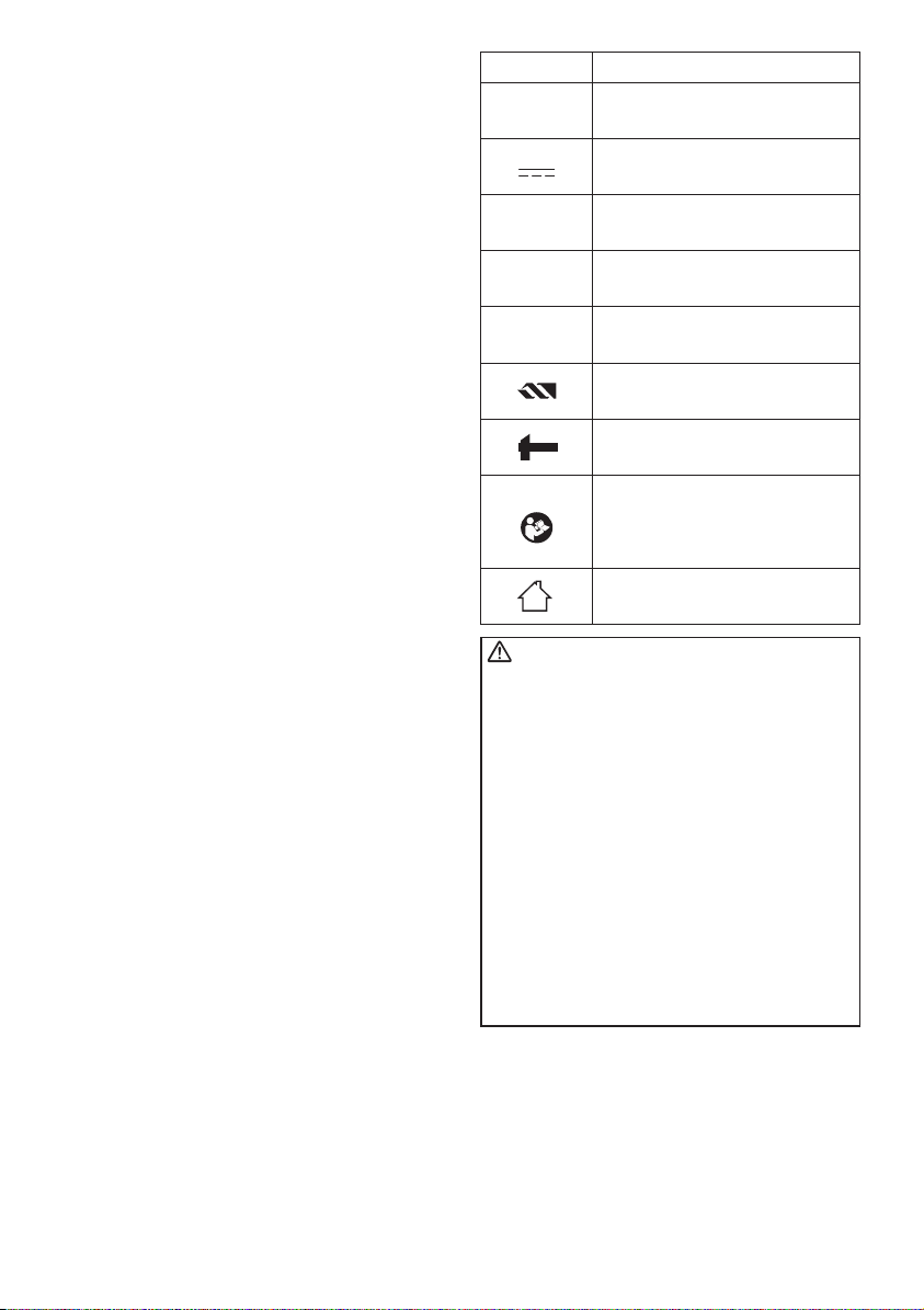
II. SPECIFIC
Symbol Meaning
SAFETY RULES
1) Wear ear protection. Exposure to
noise can cause hearing loss.
2) Be aware that this tool is always in
an operating condition, since it does
not have to be plugged into an electrical outlet.
3) Hold power tools by insulated
gripping surfaces when performing an operation where the cutting
tool may contact hid den wiring.
Contact with a “live” wire will make
exposed metal parts of the tool “live”
and shock the operator.
4) If the bit becomes jammed, immediately turn the trigger switch off
to prevent an overload which can
damage the battery pack or motor.
Use reverse motion to loosen
jammed bits.
Do NOT operate the Forward/Reverse
5)
lever when the trigger switch is on.
The battery will discharge rapidly and
damage to the unit may occur.
6) When storing or carrying the tool,
set the Forward/Reverse lever to
the center position (switch lock).
7) Do not strain the tool by holding
the speed control trigger halfway
(speed control mode) so that the
motor stops. The protection circuit
will activate and may prevent speed
control operation. If this happens,
release the speed control trigger and
squeeze again for normal operation.
8) Be careful not to get dust inside the
chuck.
9) Do not touch the rotating parts to
avoid injury.
10) Do not use the tool continuously for
a long period of time. Stop using the
tool from time to time to avoid temperature rise and heat overload of
the motor.
11) Do not drop the tool.
V
n
0
… min
Ah
Revolutions or reciprocations
-1
Electrical capacity of battery
To reduce the risk of injury,
user must read and understand
Volts
Direct current
No load speed
per minutes
pack
Rotation only
Impact driver mode
instruction manual
For indoor use only
WARNING!
Some dust created by power sanding, sawing, grinding, drilling, and other construction
activities contains chemicals known to the
State of California to cause cancer, birth
defects or other reproductive harm. Some
examples of these chemicals are:
• Lead from lead-based paints
• Crystalline silica from bricks and cement
and other masonry products
• Arsenic and chromium from chemicallytreated lumber
To reduce your exposure to these chemicals: work in a well ventilated area, and
work with approved safety equipment, such
as dust masks that are specially designed
to fi lter out microscopic particles.
-
6 -

III. FOR BATTERY
CHARGER &
BATTERY PACK
Important Safety Instructions
1) SAVE THESE INSTRUCTIONS
-This manual contains important
safety and operating instructions for
battery charger.
2) Before using battery charger, read all
instructions and cautionary markings
on battery charger, battery pack, and
product using battery pack.
3) CAUTION -To reduce the risk of in-
jury, charge only Panasonic Battery
Pack as shown in last page.
Other types of batteries may burst
causing personal injury and damage.
4) Do not expose charger and battery
pack to rain or snow.
To reduce risk of damaging the electric
5)
plug and cord, pull by plug rather than
cord when disconnecting charger.
6)
Make sure cord is located so that it will
not be stepped on, tripped over, or otherwise subjected to damage or stress.
7) An extension cord should not be
used unless absolutely necessary.
Use of improper extension cord
could result in a risk of fire and electric shock. If extension cord must be
used, make sure that:
a. pins on plug of extension cord are
the same number, size and shape
as those of plug on charger.
b. extension cord is properly wired
and in good electrical condition.
c. wire size is large enough for
ampere rating of charger as
specified below.
RECOMMENDED MINIMUM AWG SIZE
OF EXTENSION CORDS FOR BATTERY
CHARGERS
AC Input
Rating.
Equal to or
greater than
0 2 18 18 18 16
Amperes
But less
than
AWG Size of Cord
Length of Cord,
Feet
25 50 100 150
8)
Do not operate charger with damaged
cord or plug-replace them immediately.
9)
Do not operate charger if it has received a sharp blow, been dropped, or
otherwise damaged in any way; take it
to a qualified service personnel.
10) Do not disassemble charger; take
it to a qualified service personnel
when service or repair is required.
Incorrect reassembly may result in a
risk of electric shock or fire.
To reduce the risk of electric shock,
11)
unplug charger from outlet before attempting any maintenance or cleaning.
12)
The charger and battery pack are specifically designed to work together. Do
not attempt to charge any other cordless
tool or battery pack with this charger.
13) Do not attempt to charge the battery
pack with any other charger.
14) Do not attempt to disassemble the
battery pack housing.
Do not store the tool and battery pack
15)
in locations where the temperature
may reach or exceed 50°C (122°F)
(such as a metal tool shed, or a car in
the summer), which can lead to deterioration of the storage battery.
16) Do not charge battery pack when the
temperature is BELOW 0°C (32°F)
or ABOVE 40°C (104°F). This is very
important in order to maintain optimal condition of the battery pack.
17) Do not incinerate the battery pack. It
can explode in a fire.
Avoid dangerous environment. Do not
18)
use charger in damp or wet locations.
19) The charger is designed to operate
on standard household electrical
power only. Do not attempt to use it
on any other voltage!
20) Do not abuse cord. Never carry
charger by cord or yank it to disconnect from outlet. Keep cord away
from heat, oil and sharp edges.
21) Charge the battery pack in a well
ventilated place, do not cover the
charger and battery pack with a
cloth, etc., while charging.
22) Use of an attachment not recommended may result in a risk of fire,
electric shock, or personal injury.
23) Do not short the battery pack. A battery short can cause a large current
flow, over heating and create the risk
of fire or personal injury.
-
7 -
24) NOTE: If the supply cord of this appliance is damaged, it must only be
replaced by a repair shop authorized
by the manufacturer, because special purpose tools are required.
25) TO REDUCE THE RISK OF ELECTRIC SHOCK, THIS APPLIANCE
HAS A POLARIZED PLUG (ONE
BLADE IS WIDER THAN THE
OTHER).
This plug will fit in a polarized outlet
only one way. If the plug does not fit
fully in the outlet, reverse the plug. If
it still does not fit, contact a qualified
electrician to install the proper outlet.
Do not change the plug in any way.
WARNING!
• Do not use other than the Panasonic
battery packs that are designed for use
with this rechargeable tool.
• Panasonic is not responsible for any
damage or accident caused by the use
of the recycled battery pack and the
counterfeit battery pack.
• Do not dispose of the battery pack in a
fire, or expose it to excessive heat.
• Do not drive the likes of nails into the battery pack, subject it to shocks, dismantle
it, or attempt to modify it.
• Do not allow metal objects to touch the
battery pack terminals.
• Do not carry or store the battery pack
in the same container as nails or similar
metal objects.
• Do not charge the battery pack in a hightemperature location, such as next to a fire
or in direct sunlight. Otherwise, the battery
may overheat, catch fire, or explode.
• Never use other than the dedicated charger to charge the battery pack. Otherwise,
the battery may leak, overheat, or
explode.
•
After removing the battery pack from the
tool or the charger, always reattach the
pack cover. Otherwise, the battery contacts
could be shorted, leading to a risk of fire.
• When the Battery Pack Has Deteriorated,
Replace It with a New One.
Continued use of a damaged battery pack
may result in heat generation, ignition or
battery rupture.
IV. ASSEMBLY
Using Keyless drill chuck
(EY9X003E)
CAUTION: • Use keyless drill chuck ONLY
in Drill Driver Mode.
This chuck is not designed to
be used in IMPACT MODE.
It can be damaged and its life
will be reduced. Moreover,
the chuck and its metal parts,
such as the push button, front
parts, and bit may become
very hot. To prevent skin
burns, use work gloves and/
or allow heated parts to cool
down before handling.
•
Make sure the work environment is safe. When
retracting drill from work
material, Keyless drill chuck
may detach if subjected to
100 kg or more of pull force.
Detachment will be sudden.
Use care and avoid excessive
force when retracting drill from
work material.
1. Attaching Keyless drill chuck
Attach the chuck by sliding the female
detent on the bottom of the chuck to
the square drive on the body.
Make sure the chuck is firmly connected to the body.
2. Inserting the bit
Insert the bit, and turn the lock collar
clockwise (looking from the front) holding the sleeve until jaws close firmly.
②
①
-
8 -
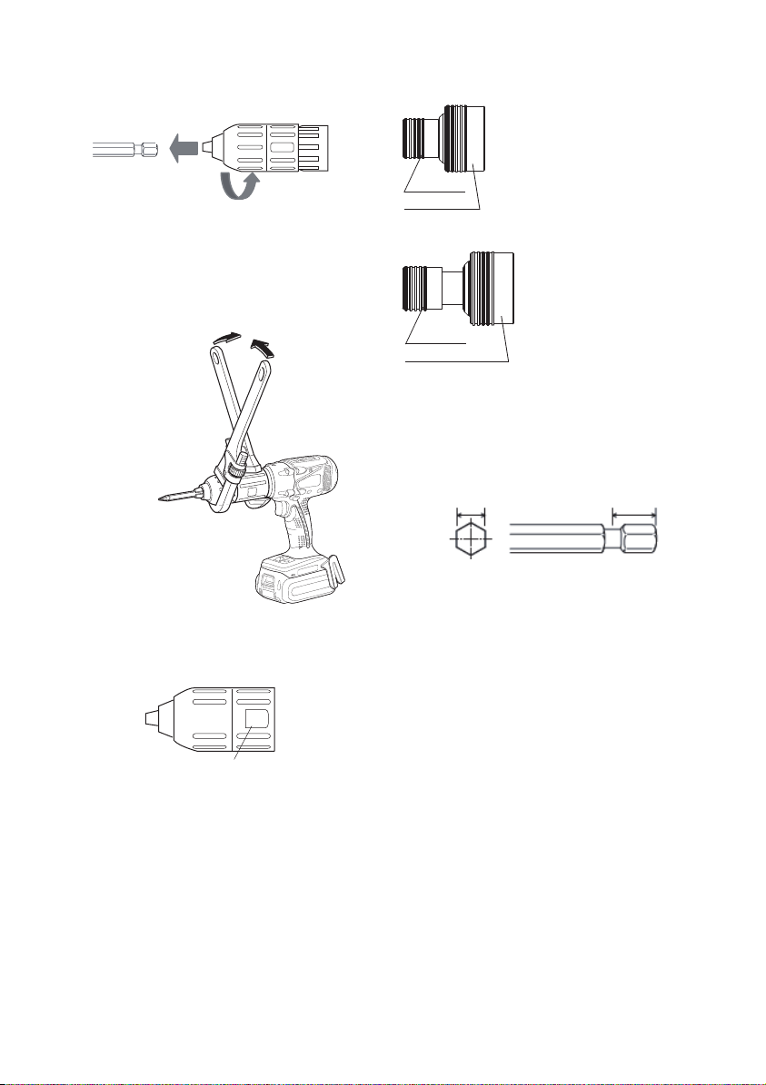
3. Removing the bit
Turn the lock collar counterclockwise
(looking from the front).
Then remove the bit.
②
①
CAUTION:
If the drill bit becomes too tight
to remove, hold two lock col-
lars with pipe wrenches and
turn them inopposite directions.
Using Quick change chuck
(EY9HX110E/EY9HX111E)
This Quick change chuck
is designed to be used
with the square drive of
Panasonic impact wrench.
Top collar
Bottom collar
EY9HX110E
Top collar
Bottom collar
EY9HX111E
Use 6.35 mm (1/4”) hexagonal bits.
To ensure proper securement of the bit,
use only hexagonal bits with 9.25 mm (3/8”)
detent.
Top collar : To insert or to
remove bit
Bottom collar : To attach or to
detach Quick
change chuck
9.25 mm (3/8”)6.35 mm (1/4”)
4. Detaching Keyless drill chuck
To detach the chuck, PUSH the button
to release the chuck from the square
drive.
PUSH
CAUTION:
Drill bit blade is sharp. Make
sure to remove the drill bit before
you set and detach the keyless
drill chuck.
CAUTION:
-
9 -
Make sure the work environment is safe. When retracting
bit from work material, Quick
change chuck may detach if
subjected to 50 kg or more of
pull force. Detachment will be
sudden. Use care and avoid
excessive force when retracting bit from work material.

1. Attaching Quick change chuck
Attach the Quick change chuck by
pulling the bottom collar forward and
sliding the female detent on the bottom of the chuck to the square drive
on the body.
Release the bottom collar to make
sure the Quick change chuck is firmly
connected to the body.
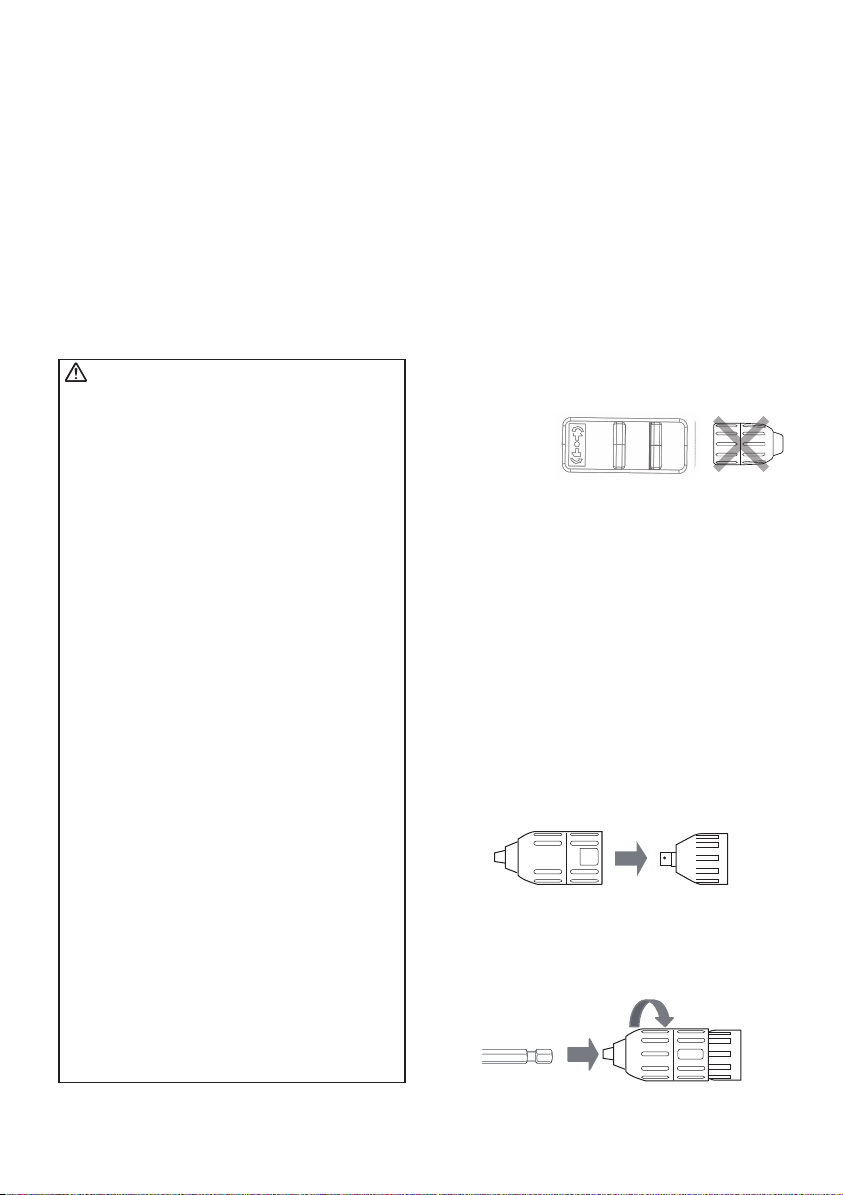
Attaching or Removing
Bat tery Pack
1. To connect the battery pack:
Align the highlighted marker points
and attach battery pack.
• Slide the battery pack until it locks
into position.
EY9HX110E
①
②
EY9HX111E
①
2. Inserting the bit
Pull the top collar of the Quick change
chuck forward, then insert the bit.
Release the bottom collar to make
sure the bit is firmly connected to the
chuck.
3. Removing the bit
Pull the top collar of the Quick change
chuck forward, then pull the bit.
CAUTION:
4. Detaching Quick change chuck
Pull the bottom collar of the Quick
change chuck forward to detach it.
lmpact mechanism creates
heat.Square drive and acces-
sory may become very hot
and may cause skinburns. To
prevent skin burns, use work
gloves and/or allow heated
parts to cool down before handling.
Alignment marks
2. To remove the battery pack:
Push down the button and slide the
battery pack forward.
Button
-
10 -

V. OPERATION
[Main Unit]
Switch Operation
1. The speed increases with the amount
of depression of the trigger. When
begin ning work, depress the trigger
slightly to start the rotation slowly.
2. A feedback electronic controller is
used to give a strong torque even in
low speed.
3. The brake operates when the trigger
is released and the motor stops immediately.
NOTE:
When the brake operates, a braking
sound may be heard. This is normal.
CAUTION:
When operating the tool by pulling the
trigger, there may be a momentary lag
before rotation starts. This does not signal a malfunction.
* This lag occurs as the tool’s circuitry
starts up when the trigger is pulled for
the first time after installing a new battery pack or after the tool has not been
used for at least 1 minute (or at least 5
minutes when the LED is on). Rotation
will start without any lag during second
and subsequent operations.
Switch and Forward/Reverse
Lever Operation
Forward
Switch lock
CAUTION:
To prevent damage, do not operate
Forward/Reverse lever until the bit
comes to a complete stop.
Reverse
Forward Rotation Switch
Operation
1. Push the lever for forward rotation.
2. Depress the trigger switch slightly to
start the tool slowly.
3. The speed increases with the amount
of depression of the trigger for efficient tightening of screws and drilling.
The brake operates and the chuck
stops immediately when the trigger is
released.
4. After use, set the lever to its center
position (switch lock).
Reverse Rotation Switch
Operation
1. Push the lever for reverse rotation.
Check the direction of rotation before
use.
2. Depress the trigger switch slightly to
start the tool slowly.
3. After use, set the lever to its center
position (switch lock).
11 -
-
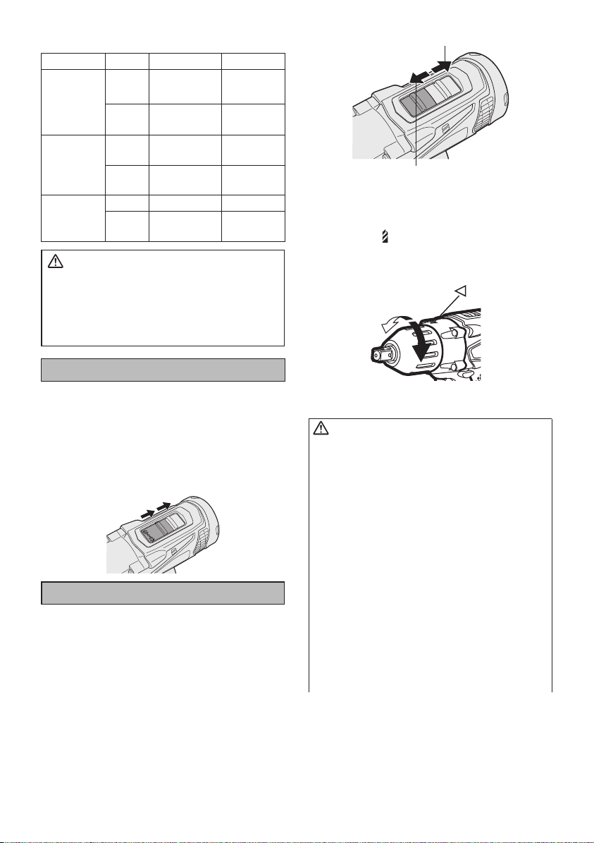
Selecting Mode
Select mode
Impact
Drill driver
High mode
Drill driver
Low mode
This tool must not be used as a drill in
“Impact Driver mode”. During drilling in
steel, the drill bit may break in case of
blocking and this may cause dangerous
cut wounds.
Impact Driver Operation
Select Impact with the mode select
switch.
• Switch to the Impact or Drill driver
High/Low position only when the tool
has completely stopped rotating.
Damage may be caused if the tool is
rotating.
Drill Driver Operation
Select Drill driver High or Low mode
with the mode select switch.
• Switch to the Impact or Drill driver
High/Low position only when the tool
has completely stopped rotating.
Damage may be caused if the tool is
rotating.
Intended use
Fastening
Driving
Driving Wood screw
Drilling Wood
Driving Wood screw
Drilling Wood
WARNING!
Work material
Bolt
Nut
Wood screw
Self-drilling screw
Self-drilling screw
Metal
Metal
Maximum size
High tensil: M12
Standard: M14
9 mm (3/8”)
6 mm (1/4”)
4.2 mm (1/8”)
6 mm (1/4”)
21 mm (7/8”)
10 mm (3/8”)
6.8 mm (1/4”)
35 mm (1-3/8”)
13 mm (1/2”)
Drill driver Low mode
Drill driver High mode
Clutch Torque Setting
Adjust the torque to one of the 21 clutch
set tings or “
CAUTION
Test the setting before actual opera tion.
Set the scale at this mark ( ).
How to Use the Belt Hook
WARNING!
• Be sure to attach the belt hook securely
to the main unit with the screw firmly
fastened. When the belt hook is not firmly attached to the main unit, the hook
may disconnect and the main unit may
fall.
This may result in an accident or injury.
• Periodically check screw for tightness. If
found to be loose, tighten firmly.
•
Be sure to attach the belt hook firmly and
securely onto a waist belt or other belt.
Pay attention that the unit does not slip off
the belt.
injury.
• When the main unit is held by the belt
hook, avoid jumping or running with it.
Doing so may cause the hook to slip
and the main unit may fall.
This may result in an accident or injury.
” position.
:
This may result in an accident or
-
12 -
• When the belt hook is not used, be sure
to return it to the storing position. The belt
hook may catch on something.
This may result in an accident or injury.
When the unit is hooked onto the waist
•
belt by the belt hook, do not attach driver bits to the unit. A sharp edge object,
such as a drill bit, may cause injury or
an accident.
To Change the Belt Hook
Location Side
The belt hook can be attached to either
side of the unit.
1. Removing the hook
(1) Remove the nut.
(2) Draw out the hook.
1
1
2
2
2. Attaching the hook to the other side
(1) Insert the hook in the other side.
(2) Tighten the nut fully so that it
securely fastened.
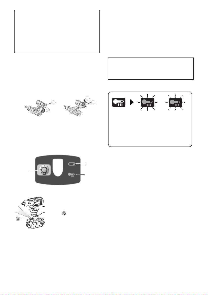
Control Panel
(3)
(1)
(1) LED light
Before the use of LED
light, always pull the power
switch once.
Press
the LED light
button.
The light illuminates with
very low current, and it
does not adversely affect the performance of the tool during use or its battery capacity.
(2)
CAUTION:
• The built-in LED light is designed to
illuminate the small work area temporarily.
•
Do not use it as a substitute for a regular
flashlight, since it does not have
enough brightness
.
• LED light turn off when the tool has
not been used for 5 minutes.
Caution : DO NOT STARE INTO BEAM.
Use of controls or adjustments or performance
of procedures other than those specifi ed herein
may result in hazardous radiation exposure.
(2) Overheat warning lamp
Off
(normal
operation)
Illuminated:
Overheat
(motor)
Indicates operation has
been halted due to motor
or battery overheating.
Flashing:
Overheat
(battery)
To protect the motor or battery, be sure
to note the following when carrying out
this operation.
• If the motor or battery becomes hot,
the protection function will be activated
and the motor or battery will stop operating. The overheat warning lamp on
the control panel illuminates or flashes
when this feature is active.
• If the overheating protection feature
activates, allow the tool to cool thoroughly (at least 30 minutes). The tool
is ready for use when the overheat
warning lamp goes out.
• Avoid using the tool in a way that
causes the overheating protection feature to activate repeatedly.
• If the tool is operated continuously under high-load conditions or if it
is used in hot-temperature conditions
(such as during summer), the overheating protection feature may activate
frequently.
-
13 -
• If the tool is used in cold-temperature
conditions (such as during winter) or if
it is frequently stopped during use, the
overheating protection feature may not
activate.
• The ambient temperature range is
between 0°C (32°F) and 40°C (104°F).
If the battery pack is used when the
battery temperature is below 0°C
(32°F), the tool may fail to function
properly.
• When charging a cool battery pack
(below 0°C (32°F)) in a warm place,
leave the battery pack at the place and
wait for more than one hour to warm
up the battery to the level of the ambient temperature.
• The performance of the EY9L42 deteriorates significantly at and below 10°C
due to work conditions and other factors.
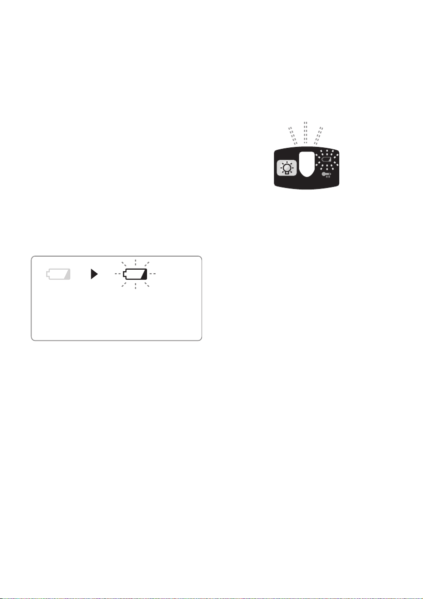
(3) Battery low warning lamp
Off
(normal
operation)
Excessive (complete) discharging of
lithium ion batteries shortens their service
life dramatically. The driver includes a
battery protection feature designed to
prevent excessive dis charging of the
battery pack.
• The battery protection feature activates immediately before the battery
loses its charge, causing the battery
low warning lamp to flash.
• If you notice the battery low warning
lamp flashing, charge the battery pack
immediately.
• If it is started with too little battery
power remaining, the tool may stop
operating without the battery low warning lamp flashing first. This indicates
that there is too little battery power
remaining to use the tool, and the bat-
Flashing
(No charge)
Battery protection
feature active
tery pack should be charged before
further use.
• If the tool is subject to a sudden load
during use that causes the motor to
lock up, the overdischarge prevention sensor may be triggered, and the
battery low warning lamp may flash.
The lamp will stop flashing once you
address the cause of the motor’s locking up and cycle the trigger.
• The battery protection feature may
activate when a high load is abruptly placed on the motor, even if ample
battery charge remains. In this case,
both the battery low warning lamp and
LED light will flash.
• If both the battery low warning lamp
and LED light flash, reduce the force
with which you are pushing on the
driver or, if using a drill driver, adjust
the speed switch to a lower setting.
Recommended Grip
Use the grip to hold and operate the
driver with one hand. If the job requires
additional force, you can push against
the rear end of the driver with your other
hand.
[Battery Pack]
For Appropriate Use of
Bat tery pack
Li-ion Battery pack
• For optimum battery life, store the Liion battery pack following use without
charging it.
• When charging the battery pack, confirm that the terminals on the battery charger are free of foreign substances such as dust and water etc.
Clean the terminals before charging
the battery pack if any foreign substances are found on the terminals.
-
14 -
The life of the battery pack terminals
may be affected by foreign substances
such as dust and water etc. during
operation.
• When battery pack is not in use,
keep it away from other metal objects
like: paper clips, coins, keys, nails,
screws, or other small metal objects
that can make a connection from one
terminal to another.
Shorting the battery terminals togeth-
er may cause sparks, burns or a fire.
• When operating the battery pack,
make sure the work place is well ventilated.
• When the battery pack is removed
from the main body of the tool, replace
the battery pack cover immediately in
order to prevent dust or dirt from contaminating the battery terminals and
causing a short circuit.
Battery Pack Life
The rechargeable batteries have a limited life. If the operation time becomes
extremely short after recharging, replace
the battery pack with a new one.
Battery Recycling
ATTENTION:
FOR Li-ion Battery Pack
A Li-ion battery that is recyclable powers
the product you have purchased. Please
call 1-800-8-BATTERY for information on
how to recycle this battery.
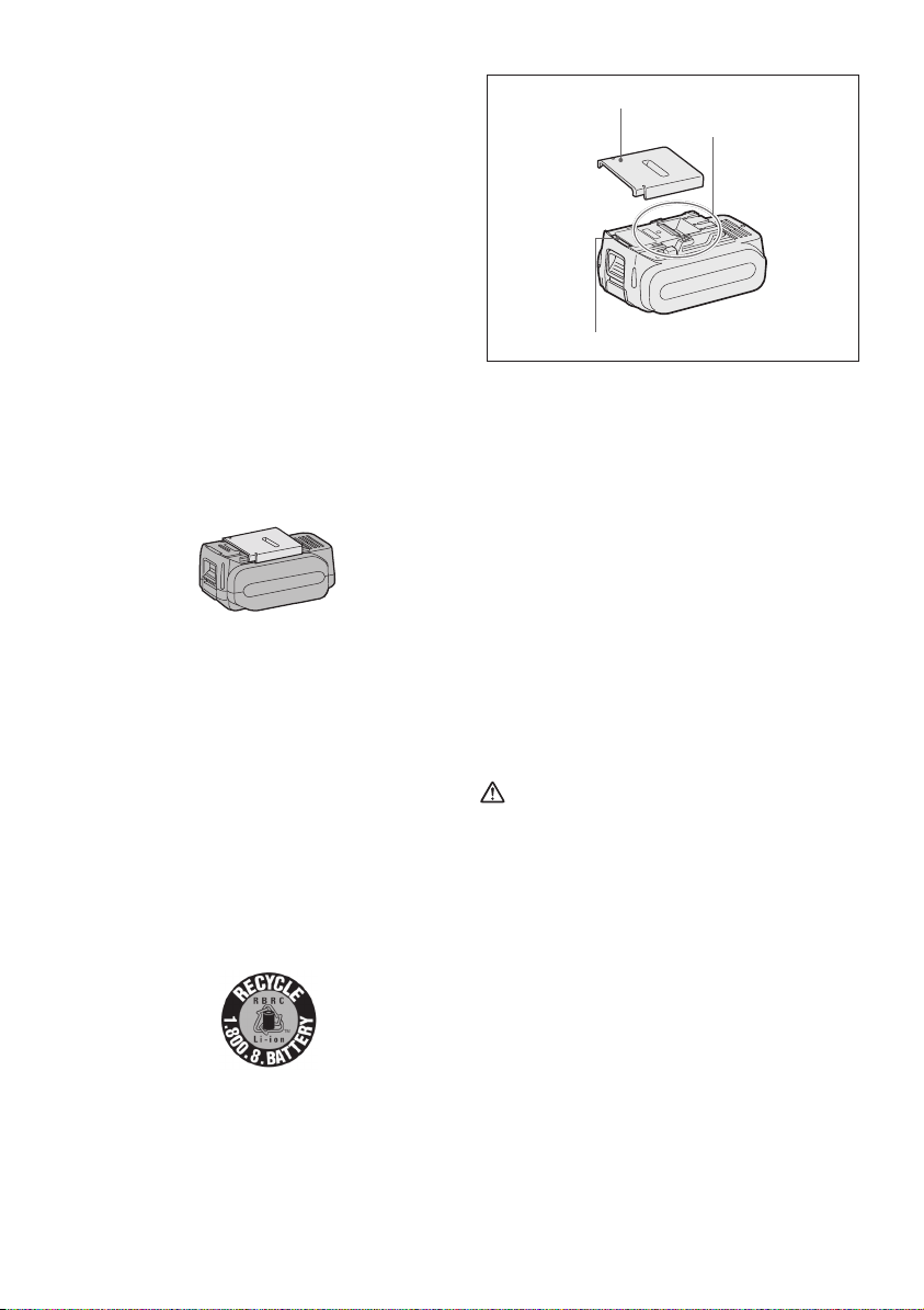
Recommendations for use
Pack cover
Terminals
Label
Be sure to use the Pack cover
When the battery pack is not being
•
used, store the battery in a way that
foreign substances such as dust and
water etc. do not contaminate the terminals. Be sure to attach the battery pack
cover to protect the battery terminals.
• When charging the battery pack, confirm that the terminals on the battery
charger are free of foreign substances
such as dust and water etc. Clean the
terminals before charging the battery
pack if any foreign substances are
found on the terminals.
The life of the battery pack terminals
may be affected by foreign substances
such as dust and water etc. during
operation.
CAUTION:
To protect the motor or battery, be sure
to note the following when carrying out
operation.
• If the motor and battery becomes hot, the
protection function will be activated and
the motor and battery will stop operating.
For safe use
•
The battery pack is designed to be
installed by proceeding two steps for safety. Make sure the battery pack is installed
properly to the main unit before use
•
If the battery pack is not connected firmly
when the switch is switched on, the
overheat warning lamp and the battery
low warning lamp will flash to indicate
that safe operation is not possible, and
the main unit will not rotate normally.
Connect the battery pack into the unit of
the tool until the red or yellow label disappears.
.
-
15 -
[Battery Charger]
Charging
CAUTION:
•
The charger is designed to operate on
standard domestic electrical power only
as stated in the rating plate. Charge
only on the voltage indicated on the
rating plate of unit. e.g.230v / 50Hz
• Do not attempt to use it on any other
voltage or frequency rating!
• If the temperature of the battery pack
falls approximately below −10°C (14°F),
charging will automatically stop to prevent degradation of the battery.
•
The ambient temperature range is
between 0°C (32°F) and 40°C (104°F).
If the battery pack is used when the battery temperature is below 0°C (32°F), the
tool may fail to function properly.
• Use the charger at temperatures
between 0°C and 40°C, and charge
the battery at a temperature similar to
that of the battery itself. (There should
be no more than a 15°C difference
between the temperatures of the battery and the charging location.)
• When charging a cool battery pack
(below 0°C (32°F)) in a warm place,
leave the battery pack at the place and
wait for more than one hour to warm up
the battery to the level of the ambient
temperature.
•
Cool down the charger when charging
more than two battery packs consecutively.
• Do not insert your fingers into contact hole, when holding charger or any
other occasions.
CAUTION:
To prevent the risk of fire or damage
to the battery charger.
• Do not cover vent holes on the charger and the battery pack.
• Unplug the charger when not in use.
NOTE:
Your battery pack is not fully charged at
the time of purchase. Be sure to charge
the battery before use.
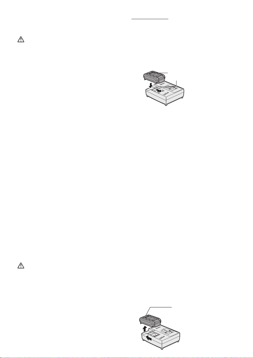
How to charge
1. Plug the charger into the AC outlet.
2.
Insert the battery pack firmly into the
charger.
1. Line up the alignment marks and
place the battery onto the dock on
the charger.
2. Slide forward in the direction of the
.
arrow.
Alignment marks
3.
During charging, the charging lamp will
be Illuminated.
When charging is completed, an internal electronic switch will automatically
be triggered to prevent overcharging.
• Charging will not start if the battery
pack is warm (for example, immediately after heavy-duty operation).
The orange standby lamp will be
flashing until the battery cools down.
Charging will then begin automati-
cally.
4. The charge lamp (green) will flash
slow ly once when the battery is approxi mately 80% charged.
5. When charging is completed, the charging lamp in green color will turn off.
6. If the temperature of the battery pack
is 0°C or less, charging takes longer to
fully charge the battery pack than the
standard charging time.
Even when the battery is fully charged,
it will have approximately 50% of the
power of a fully charged battery at normal operating temperature.
7. Consult an authorized dealer if the
charging lamp (green) does not turn off.
8. If a fully charged battery pack is inserted into the charger again, the
charging lamp lights up. After several
minutes, the charging lamp in green
color will turn off.
9. Remove the battery pack while the
battery pack release button is held up.
Battery pack
release button
-
16 -
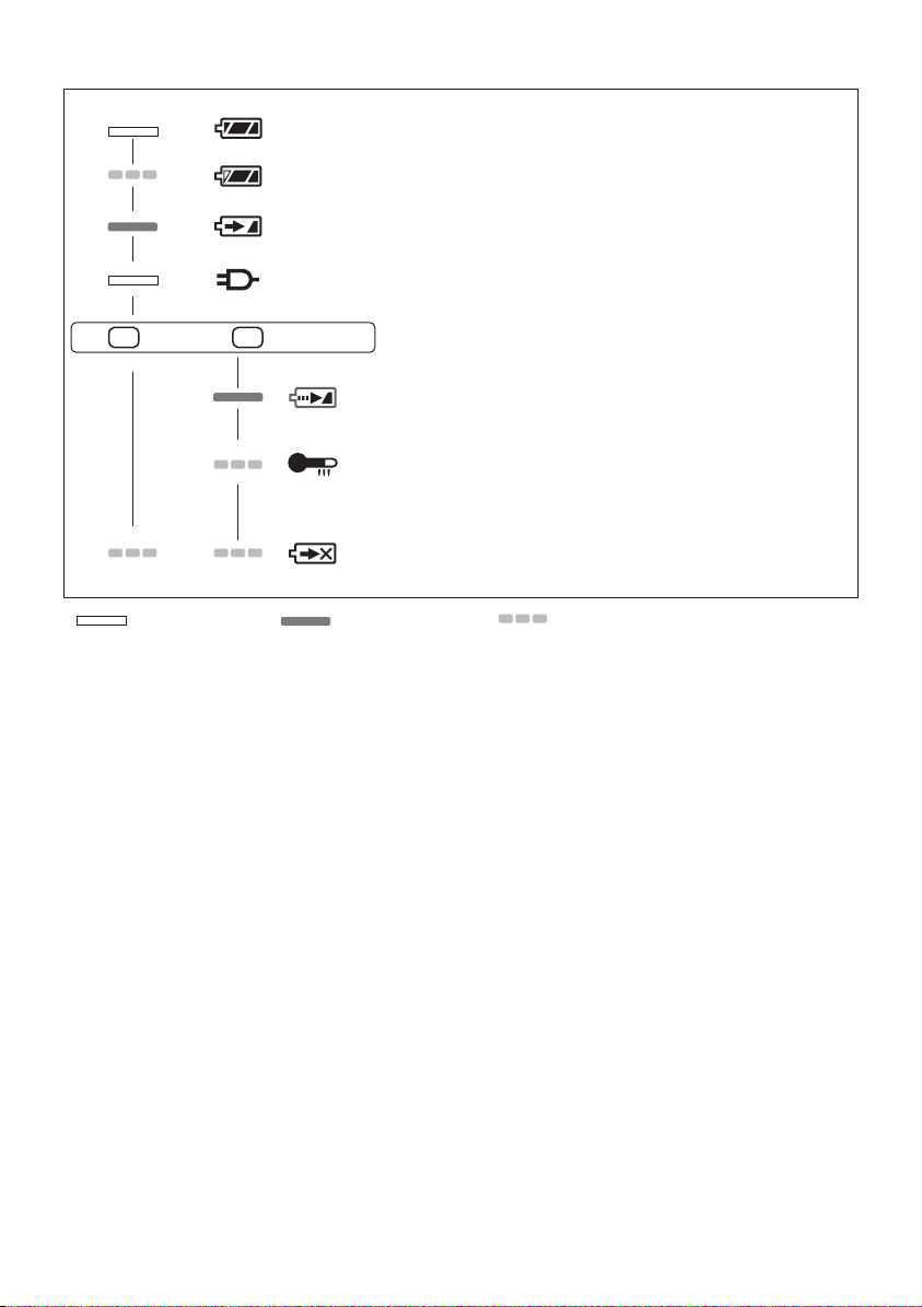
LAMP INDICATIONS
Charging is completed. (Full charge.)
Battery is approximately 80% charg ed.
Now charging.
Charger is plugged into the AC outlet.
Ready to charge.
(Green) (Orange)
Turn off Illuminated Flashing
Charging Status Lamp
Left: green Right: orange will be displayed.
Battery pack is cool.
The battery pack is being charged slowly to reduce the load on the
battery.
Battery pack is warm.
Charging will begin when temperature of battery pack drops. If the
temperature of the battery pack is –10°C (14°F) or less, the charging
status lamp (orange) will also start fl ashing. Charging will begin when
the temperature of the battery pack goes up.
Charging is not possible. Clogged with dust or malfunction of the
battery pack.
Federal Communication Commission Interference Statement
This equipment has been tested and found to comply with the limits for a Class B
digital device, pursuant to Part 15 of the FCC Rules. These limits are designed to
provide reasonable protection against harmful interference in a residential installation.
This equipment generates, uses and can radiate radio frequency energy and, if not
installed and used in accordance with the instructions, may cause harmful interference
to radio communications. However, there is no guarantee that interference will not
occur in a particular installation. If this equipment does cause harmful interference to
radio or television reception, which can be determined by turning the equipment off
and on, the user is encouraged to try to correct the interference by one of the following
measures:
• Reorient or relocate the receiving antenna.
• Increase the separation between the equipment and receiver.
• Connect the equipment into an outlet on a circuit different from that to which the
receiver is connected.
• Consult the dealer or an experienced radio/TV technician for help.
FCC Caution: To assure continued compliance, install and use in accordance
with provided instructions. Use only the battery pack specified in the instructions.
Any changes or modifications not expressly approved by the party responsible for
compliance could void the user’s authority to operate this equipment.
This device complies with part 15 of the FCC Rules. Operation is subject to the
following two conditions: (1) This device may not cause harmful interference, and (2)
this device must accept any interference received, including interference that may
cause undesired operation.
This Class B digital apparatus complies with Canadian ICES-003.
17 -
-

VI. MAINTENANCE
• Use only a dry, soft cloth for wiping the unit. Do not use a damp cloth, thinner, benzine, or other volatile solvents for cleaning.
• In the event that the inside of the tool or battery pack is exposed to water, drain
and allow to dry as soon as possible. Carefully remove any dust or iron filings that
collect inside the tool. If you experience any problems operating the tool, consult
with a repair shop.
VII. ACCESSORIES
Use only bits suitable for size of drill’s chuck.
Use Panasonic original Optional Keyless drill chuck (EY9X003E) and Quick change
chuck(EY9HX111E) for maximum performance.
VIII. APPENDIX
MAXIMUM RECOMMENDED CAPACITIES
Screw
driving
Bolt fastening Impact mode Standard bolt: M14
Drill Steel Drill driver High mode
Wood screw Impact mode
Drill driver High mode
Drill driver Low mode
Self-drilling screw Impact mode
Drill driver High mode
Drill driver Low mode
Wood Drill driver High mode
Drill driver Low mode
9 mm (3/8”)
4.2 mm (1/8”)
6.8 mm (1/4”)
6 mm (1/4”)
6 mm (1/4”)
High tensile bolt: M12
10 mm (3/8”)
13 mm (1/2”)
21 mm (7/8”)
35 mm (1 - 3/8”)
WARRANTY SUPPLEMENT
The breakdown and damage caused by usage consistent for a long time (e.g.: factory
work on the assembly line, etc.) is out of warranty.
-
18 -
 Loading...