

Page 1
Operation Manual
Centralized Control System
CZ-CWEBC2
Web Interface
Thank you for choosing the CZ-CWEBC2
Web Interface.
Before using the system, be sure to read this
manual carefully. In particular, be sure to read
the “Important Safety Instructions”.
After reading this manual, store it in a
convenient place.
Contents
1. Important Safety Instructions .......................... 3
2. Features of the System..................................... 7
3. System Confi guration ...................................... 8
4. Names and Functions of Parts ......................... 9
5. Preparations and Login .................................. 12
6. Status/Control ................................................. 14
7. Maintenance .................................................... 21
8. Initial Settings ................................................. 24
9. Auxiliary Settings ............................................ 35
10. Supplementary Information ......................... 45
11. Troubleshooting ............................................ 48
12. Care ................................................................ 50
13. Specifi cations ................................................ 51
Page 2

Centralized Control System
CZ-CWEBC2
Web Interface
Operation Manual
Page 3
Contents
1 Important Safety Instructions ....................................................................... 3
2 Features of the System .................................................................................. 7
3 System Confi guration ....................................................................................8
4 Names and Functions of Parts ......................................................................9
5 Preparations and Login ................................................................................ 12
5.1 Turning the Web Interface On ............................................................... 12
5.2 Checking the PC ..................................................................................... 12
5.3 Log-in...................................................................................................... 12
6 Status/Control ..............................................................................................14
6.1 Displaying general information by tenant........................................... 14
6.2 Displaying detailed information by tenant .......................................... 19
6.3 All Units .................................................................................................. 20
7 Maintenance .................................................................................................21
7.1 Alarm Log ............................................................................................... 21
7.2 Sent Mail Log ......................................................................................... 22
8 Initial Settings ............................................................................................... 24
8.1 Date and Time Setting .......................................................................... 24
8.2 Unit/Tenant .............................................................................................26
8.3 WEB Settings .......................................................................................... 28
8.4 User Settings ......................................................................................... 30
Main
Main
Main
Main
Main
Main
Main
Main
Main
111
Sub
1
1
Sub
1
1
Sub
2
2
Sub
2
2
Sub
3
3
Sub
3
3
Sub
3
3
Sub
3
3
Sub
1
2
3
1
2
2
3
2
3
1
2
1
2
3
4
1
4
9 Auxiliary Settings.......................................................................................... 35
9.1 Program Timer ....................................................................................... 35
9.2 Tenant holiday/Timer special day ......................................................... 37
9.3 Prohibiting remote control use ............................................................ 39
9.4 Other settings ........................................................................................ 41
10 Supplementary Information ...................................................................... 45
11 Troubleshooting ........................................................................................... 48
12 Care .............................................................................................................. 50
13 Specifi cations .............................................................................................. 51
Main
Main
Main
Main
4
4
4
4
4
4
4
4
Sub
Sub
Sub
Sub
1
4
1
2
3
2
3
4
[Note]
The screen display examples in this manual are for explanation use and may be different from
the displays of air conditioners actually used.
The screen displays may also vary, depending on the operating system of your PC and the
Web browser you use.
2
Page 4
1 Important Safety Instructions
Before using the system, be sure to read these “Important Safety Instructions”.
The precautions given in this manual consist of specifi c “ Warnings”
and “
Cautions”. They provide important safety related information
and are important for your safety, the safety of others, and trouble-free
operation of the system. Be sure to strictly observe all safety procedures.
• The labels and their meanings are as described below.
This refers to a hazard or unsafe procedure or practice which can result
Warning
Caution
• Meaning of symbols
Indicates “Warning” or “Caution”.
Indicates “Prohibited”.
Indicates an action that should always be performed.
in severe personal injury or death.
This refers to a hazard or unsafe procedure or practice which can result
in personal injury or product or property damage.
• After reading this manual, save it in a convenient place.
Be sure to provide this manual to any person who may use the product.
Installation Precautions
Warning
Do not install by yourself.
Installation should always be
performed by your dealer or a
professional service provider.
Electric shock or fi re may result
if an inexperienced person
performs any installation or
wiring procedures incorrectly.
Electrical work must be carried
out by qualifi ed personnel.
Contact your dealer for
installation. Do not attempt to
install the product by yourself.
Use only specifi ed air conditioners.
Always use only air conditioners
specifi ed by dealer. Installation
should always be performed by
a professional service provider.
Electric shock or fi re may result
if an inexperienced person
performs any installation or
wiring procedures incorrectly.
Avoid installation in the
following locations:
Locations subject to
infl ammable gas leakage
3
Page 5
1 Important Safety Instructions
Caution
Do not install in damp locations
or locations subject to vibrations.
Damage to the system can result.
Do not install near sources of
noise.
Malfunctions can result.
Elevators, automatic doors,
industrial machinery, etc.
Avoid installation in the
following locations:
• Near beaches or other places
with a large amount of salt
• Hot springs or other locations
subject to sulfuric gas
•
Locations subject to water
and oil (including industrial
lubricants) sprays and high
humidity
• Locations with large changes
in voltage
• Near machines generating
electromagnetic waves
• Locations close to organic
solvents
Do not install under direct sunlight
or in places near heat sources.
Damage to the system can result.
Avoid static electricity during
cabling work.
Before starting cabling work,
touch ground to discharge static
electricity from the body.
Keep televisions, radios, PCs,
etc, at least 1 m away from the
Centralized Control System, indoor
units, and remote controllers.
Picture breakup and noise can
occur.
Do not use heaters near the
Centralized Control System.
The Centralized Control System
may malfunction because the
temperature becomes outside
the range of the operating
temperature for the system.
Use remote controllers or
system controllers together.
Should the Centralized Control
System fail, operation of air
conditioners is disabled with
the Centralized Control System.
Be sure to use the remote
controllers or system controllers
together.
4
Page 6
1 Important Safety Instructions
Precautions for Use
Warning
Do not touch switches with wet hands.
Electric shock and damage to
the system can result.
Prohibited
Protect the Web Interface
from water.
Damage to the system can
result.
Prohibited
Stop the system and turn the power off if you sense unusual smells
or other irregularities.
Continuing operation when the system is out of order can result in electric shock,
fi re, and damage to the system. Contact your dealer.
Turn off
the power.
Caution
Do not drop the system or
subject it to strong shocks.
Damage to the system can result.
Prohibited Prohibited
Use only fuses with the correct
capacity.
Use only the specifi ed power source.
Use of any other power source can result in fi re and damage to the system. Use
single-phase 100-240 V AC power.
Use of pins or copper wire can
result in fi re and damage to the
system.
5
Page 7
1 Important Safety Instructions
Moving and Repair Precautions
Warning
Do not disassemble or repair.
Never disassemble or repair
the system by yourself. Contact
your dealer for repair. Electric
shock or fi re may result if an
Prohibited
inexperienced person attempts
to repair the system.
Contact your dealer before
moving the system.
Contact your dealer or a
professional service provider
about moving and reinstalling
the system. Electric shock or fi re
Contact
your dealer
may result if an inexperienced
person performs any installation
procedures incorrectly.
6
Page 8
2 Features of the System
The Web Interface is a centralized air conditioning management system dedicated to PAC and
GHP for small-sized buildings.
Operations and status monitoring of air conditioners can be performed by a customer's PC
after logging into the Web Interface.
• Number of connectable units ......... • Up to 64 indoor units can be connected to one Web Interface.
• Up to 30 outdoor units can be connected.
• Display ............................................. No display unit is provided with this product. Operations are
• Operation functions ........................ Start and stop, temperature settings, operation mode
• Operation monitoring ..................... Monitoring of operation status (operating/stopped, operation
• Program timers ............................... Up to 50 types of weekly timers can be programmed by
• Supported languages ..................... The following languages are supported, and you can select a
•
performed from and indications are displayed on a customer's
PC after login.
•
selection, fan speed settings, fan direction settings, prohibition
of use of remote controllers, ventilation, and resetting of filter
cleaning sign
•
mode, etc.) and alarms
fi fo gnirotinoM • lter cleaning signs
sgol mrala fo yalpsiD •
•
combining 50 types of daily timers (50 times per day).
• Programs for a tenant holiday and five types of timer special
days can be set.
•
language when logging in by entering a language code:
English
French
German
Italian
Portuguese
Spanish
Terms and abbreviations used in this manual and in the system software
noitaiverbbAmret lluF
Outdoor unit system address Outdoor unit system, Outdoor unit, Outdoor system, Outdoor, O/D
Indoor unit address Indoor unit, Indoor, I/D
Tenant number Tenant No., Tenant
Unit name
Central control address Central address, CNTR
Unit
7
Page 9
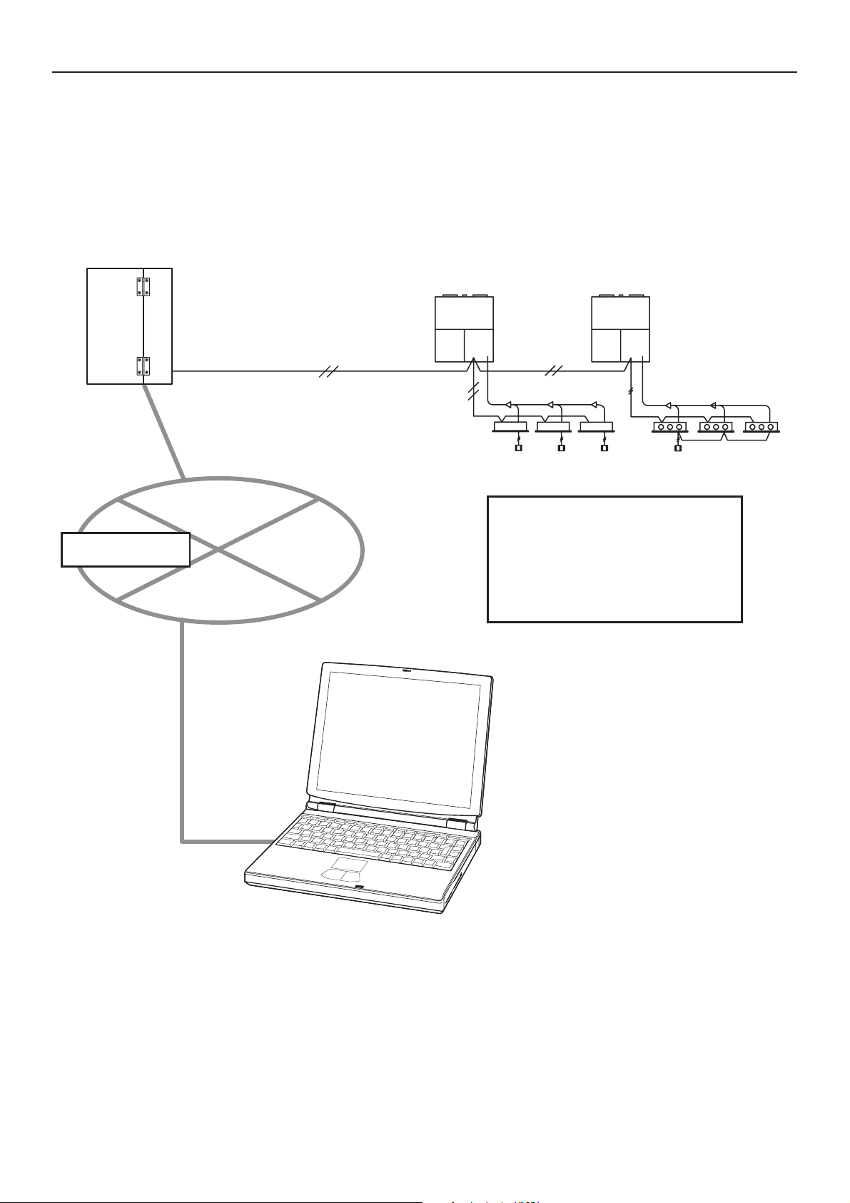
3 System Confi guration
System Configuration Example
Web Interface
Intranet
Inter-unit
control wire
(non-polar)
LAN (10/100BASE-T)
Link system
Maximum number of connections:
Indoor units: 64
Outdoor units: 30
Link system (Inter-unit
control wire) : 1
PC (Customer's)
8
Page 10
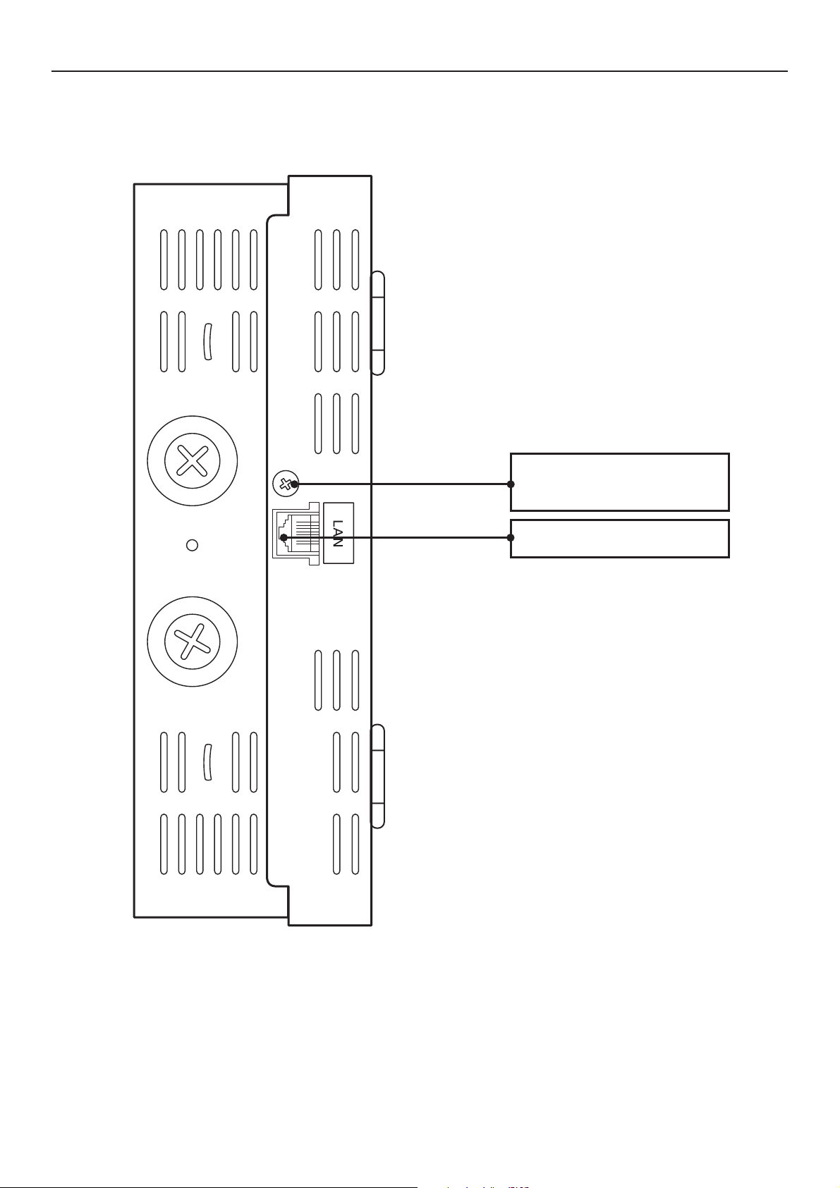
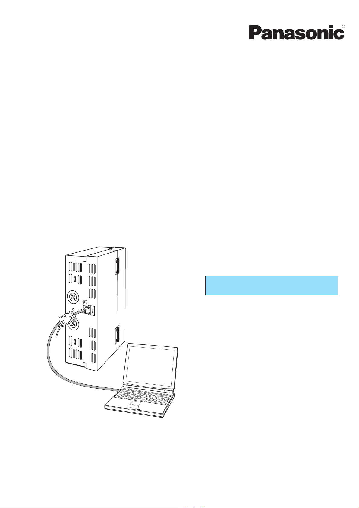
4 Names and Functions of Parts
• Exterior
To open the cover,
remove this screw.
Connect a LAN cable.
9
Page 11
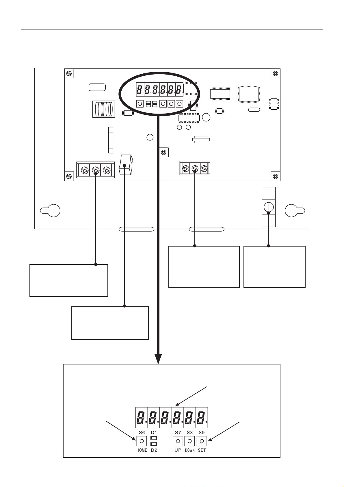
4 Names and Functions of Parts
• Under the cover
Power supply terminals
Connect to a power
source (100–240 V ~).
Power switch
For turning the Web
Interface on or off
HOME key
Inter-unit control
wire terminals
Connect control wires
for air conditioners.
Display and Operation Section
7-segment LEDs
UP/DOWN/SET
keys
Earth terminal
Connect a
shielded cable for
communications.
10
Page 12

4 Names and Functions of Parts
[Notes on Connecting a LAN cable]
• Use a LAN cable of Category 5* or higher standards.
• Be sure to attach the supplied ferrite core at one end of the LAN cable (Web Interface side).
Use a cable tie to make sure the ferrite core stays in place.
•Take security measures, such as installing a firewall, in order to protect this system against
external unauthorized access.
• For details on connections and settings, consult the network administrator of the field site.
*Category 5
The standards for telecommunications cabling systems defined by the Telecommunications
Industry Association (TIA) and the Electronic Industries Alliance (EIA). Up to 100 MHz
frequencies can be used for telecommunications.
Straight and cross cables can be used. Straight cables are used for connections between a PC
and a hub, and the Web Interface and the hub. Cross cables are used for directly connecting
the Web Interface and a PC.
11
Page 13
5 Preparations and Login
5.1 Turning the Web Interface On
After checking the connection with the air conditioners and making sure that all the air
conditioners are ON, set the Power switch of the Web Interface to ON.
5.2 Checking the PC
The following environment is required for a customer's PC to access the Web Interface for
operations of air conditioners:
(The system may not function properly in an environment other than that mentioned
below.)
(1) Browser : Microsoft Internet Explorer 6.0
(2) Java applet : Sun Microsystems Java Plugin Ver1.4.2
* Free downloading is possible from
http://www.java.com/ja/download/manual.jsp.
(3) Communications protocol : IPV4 (IPV6 not supported)
(4) Display resolutions : XGA (1024 × 768 dots) or higher recommended
5.3 Log-in
Enter the following in the address bar of the Web browser on the PC:
IP address : IP address that has been set for the Web Interface unit
The factory default settings are “192.168.1.1” and the DHCP “Invalid”.
ID name : “Device Name” that has been set for the Web Interface unit
The ID name is required when the DHCP server is to be used.
Language code (Enter with one-byte characters.)
English: en French: fr German: de
Italian: it Portuguese: pt Spanish: es
[Example]
In a case where the IP address of the Web Interface is “10.31.139.212” and you are accessing
English pages
http://[ or ]/sacwww/index_[].asp
http://10.31.139.212/sacwww/index_en.asp
In a case where a DHCP server is used and the ID name (device name) of the Web Interface
is “WindowsCE0”
http://WindowsCE0/sacwww/index_en.asp
12
Page 14
5 Preparations and Login
13
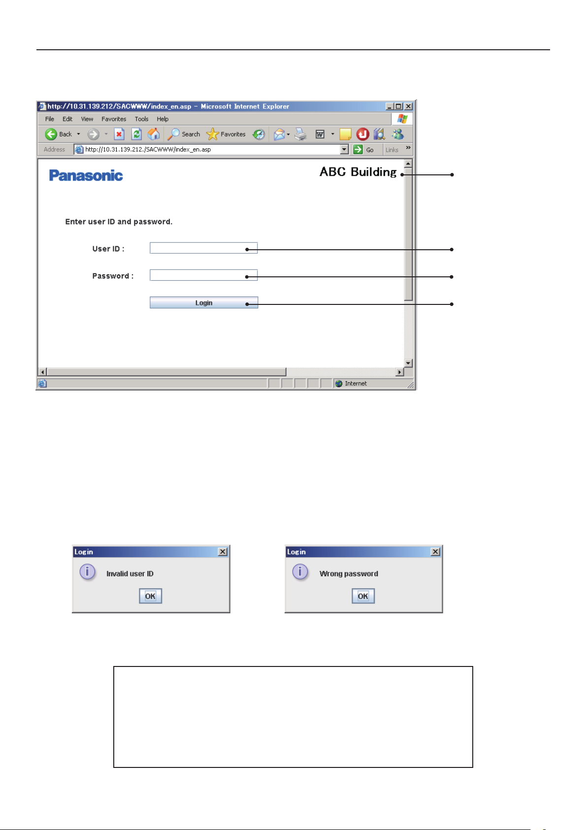
If the network works properly, the following login screen is displayed:
Log in using the user ID and password that have been set for the Web Interface.
The “Site name” that has been set for the Web Interface is displayed.
Enter the “User ID” that has been set for the Web Interface.
Enter the “Password” that has been set for the Web Interface.
Click on this button to log in.
If a wrong user ID or password is entered, the following message will be displayed:
After login is executed properly, the “Each tenant” screen (next page) will be displayed.
At the factory, the Administrator user shown below is registered.
After logging in using this administrator user account, change the
password:*
User ID : administrator
Password : admin
*For details on how to change the password, see “8.4 User Settings”.
Page 15
14
6 Status/Control
Main Sub
1 1
6.1 Displaying general information by tenant
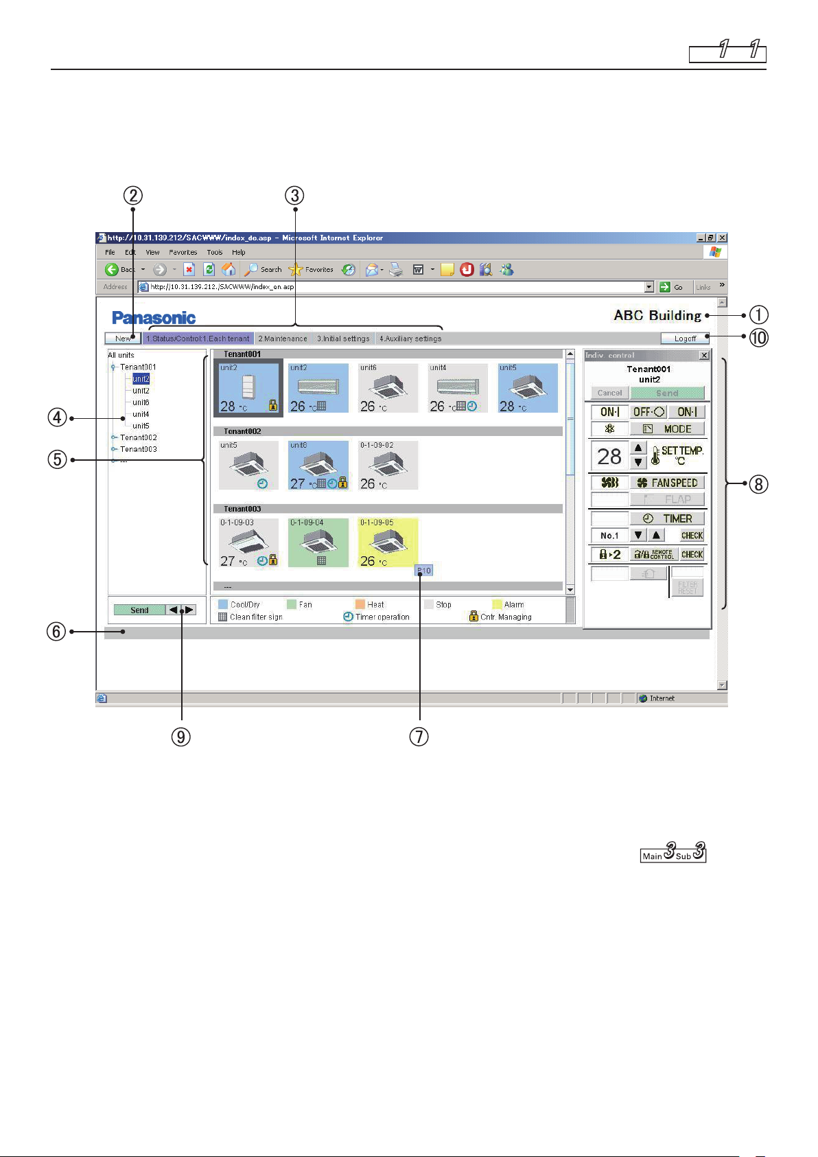
When you log in the Web Interface, or when “1. Status/Control: 1. Each tenant” is selected
from the menu, the screen shown below is displayed.
(The details of the displayed screen vary, depending on the type of account used for login.)
In a case of group control, only the main units will be displayed.
Site name
The “Site name” that has been specifi ed on the “WEB settings” screen ( ) is
displayed.
“New” button
For updating the data on the screen to the latest data. This button is displayed on every
screen.
Page 16
6 Status/Control
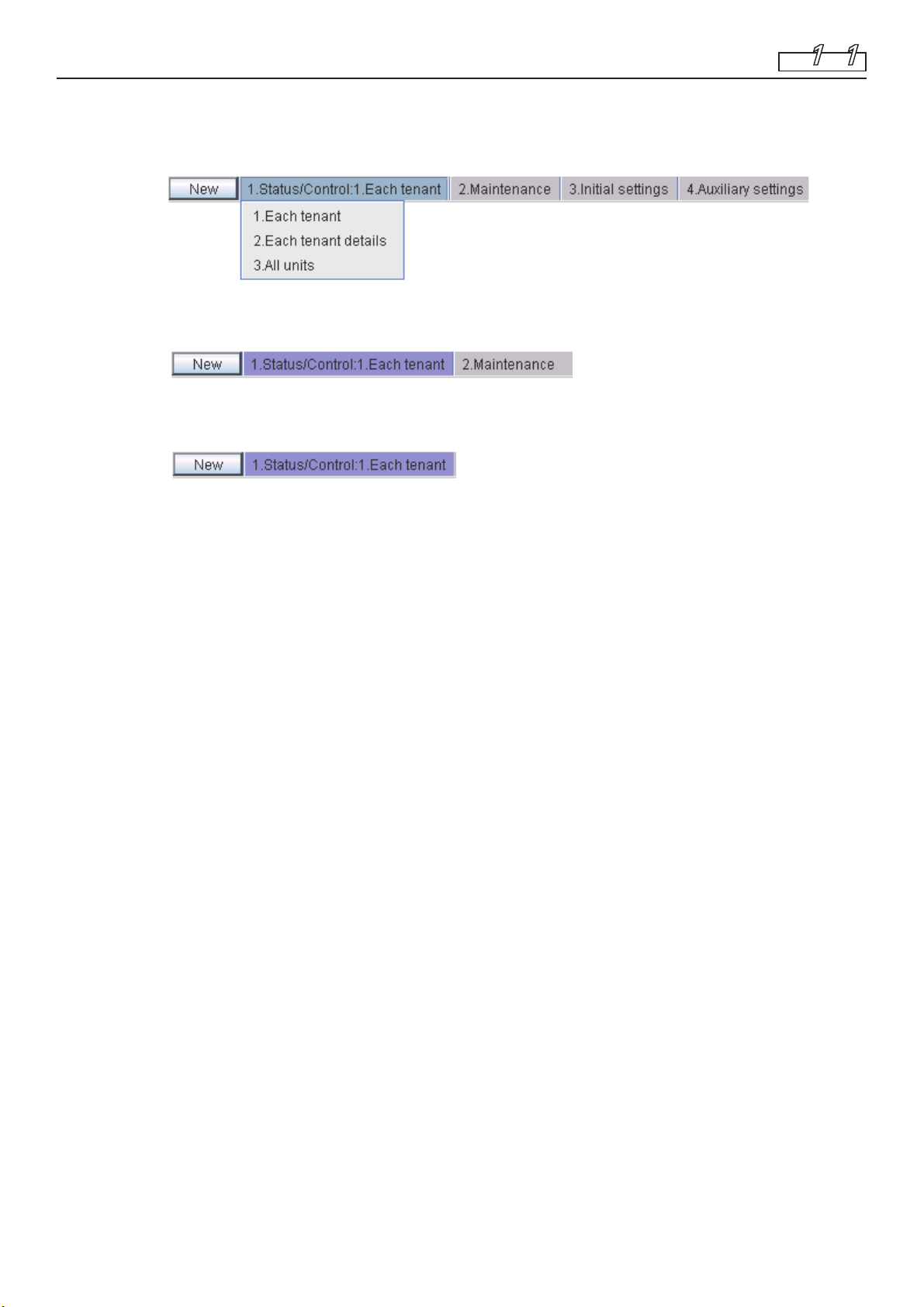
Menu (The displayed menu varies, depending on the type of account used for login.)
Select a screen by displaying the pulldown menu, as shown below.
★ Menu for the “Admin.” (Administrator) user
★ Menu for a “Special” user
★ Menu for a “General” user
11
Main Sub
Tree view section
A tree view of relationships among the indoor units that are connected with the Web
Interface and tenants is displayed.
Indoor units and tenants to be selected vary, according to which part of the tree you click on.
Each indoor unit is selected when an indoor unit name (highlighted part in the screen
example) is clicked on.
When a tenant name is clicked on, all the units belonging to the tenant are selected.
All indoor units are selected when the top line (“All units” in the screen example) of the
tree is clicked on.
According to the type of account used for login (Admin, Special, or General), only the
operable tenants will be displayed.
Icon display section
The indoor units connected with the Web Interface are displayed with icons.
For details on the meanings of colors and symbols of the icons, see the legend displayed
below the icon display section.
When an indoor unit icon is clicked on, that indoor unit is individually selected, and the
selected indoor-unit icon is indicated with an inversed frame.
When a tenant name is clicked on, all the indoor units belonging to that tenant are
selected, and all the indoor-unit icons are indicated with highlighted frames.
While any of the icons is selected, the display for the corresponding remote controller ()
is displayed.
Notifi cation column
The communication status between the Web browser and the Web Interface is displayed.
For example, while a screen is being updated, “Updating” is displayed.
When settings for an indoor unit are changed, while those data are being sent, “Sending”
is displayed.
Alarm code display
If you move the cursor onto the icon of the indoor unit from which an alarm has been
issued, an alarm code will be displayed after about 1 second.
15
Page 17

6 Status/Control
Remote control window
If any of the indoor units is selected, the remote control window shown below will be
displayed for detailed setting modifi cations.
Main Sub
Selected tenant and
unit names
CD
11
E
AB
A: Status/Control screen section
The status and operations of the selected air conditioner are displayed.
If a setting is changed, the background color of the changed item will turn green, and
the “Send” button will be enabled.
In the above example, the background color for the items of start/stop, setting
temperature, and fan speed is green.
When the “Send” button is clicked on, data for all changes are enabled and sent to the
Web Interface.
To disable the changes made, click on the “Cancel” button or select another air
conditioner.
B: Control section
The settings for start/stop, operation mode, setting temperature, fan speed, and swing/
fan direction can be changed.
16
Page 18

6 Status/Control
C: Send button
For sending all the changes made so far to the Web Interface.
The settings of the air conditioner will not be changed until the data for the changes
are sent using this button.
D: Cancel button
For cancelling all the changes made so far.
E: Check buttons for timer setting and remote controller prohibition setting
For displaying a check screen for the corresponding settings.
(See “Tenant holiday/Timer special day” and “Prohibiting remote control use”.)
To return to the previous screen, click on the “Return” button.
* For a user who has logged in using the “General” user account, the buttons that have been
set as prohibited will be disabled.
In addition, the “R/C” button and the “Check” button on its right will not be displayed.
11
Main Sub
Remote controller for a “General” user
17
Page 19

6 Status/Control
Display order change buttons
For changing the display order of indoor units
After selecting an indoor unit whose order you wish to change, click on the “
“
” button. Each time the “ ” button is clicked on, the order of the indoor unit will
move one place upward in the tree or leftward in the icon display section.
Each time the “
downward in the tree or rightward in the icon display section.
To register the changed setting, click on the “Send” button.
The changed order will be refl ected on the “Each tenant details” and “All units” screens.
“Log off” button
For logging off the currently logged-in user. The login screen will be displayed.
11
Main Sub
” or
” button is clicked on, the order of the indoor unit will move one place
18
Page 20

6 Status/Control
19
Main Sub
1 2
6.2 Displaying detailed information by tenant
When “1. Status/Control: 2. Each tenant details” is selected from the menu, the screen shown
below is displayed. (The details of the displayed screen vary, depending on the type of
account used for login.)
When any of the indoor units is clicked on, the remote controller screen will be displayed.
Operations on this screen are the same as those on the “Each tenant” screen. See the
relevant heading.
Even in a case of group control, the main units, as well as sub unit, are displayed.
The indications for sub units are grayed, and the remote controller screen will not open if you
click on a grayed indication. To open the remote control screen, select the main unit.
For sub units, the cells for the fl ap setting and remote controller prohibition setting are blank.
Page 21

6 Status/Control
6.3 All Units
When “1. Status/Control: 3. All units” is selected from the menu, the screen shown below is
displayed.
(The details of the displayed screen vary, depending on the type of account used for login.)
A maximum of 64 indoor units are displayed on a screen. In a case of group control, sub
units, as well as main units, are displayed.
Operations on this screen are the same as those on the “Each tenant” screen. See the
relevant heading.
When any of the indoor units is clicked on, the remote controller screen will be displayed.
13
Main Sub
As the number of indoor units increases, the display space for one unit will be reduced. As a
result, part of a unit name may become hidden.
20
Page 22

21
7.1 Alarm Log
If you log in using the administrator or special user account, when “2. Maintenance: 1. Alarm
log” is selected from the menu, the screen shown below is displayed.
When an indoor unit is selected in the tree, the latest 14 alarm logs will be displayed.
If 15 or more alarms are issued, all but the latest 14 logs will be erased.
A log for restoration from an error will not be recorded.
The content of an alarm is indicated with an alarm code.
For details on the meanings of alarm codes, refer to the operation manual of the air
conditioners or consult your service representative.
7 Maintenance
Main Sub
2 1
Page 23

7 Maintenance
22
Main Sub
2 2
7.2 Sent Mail Log
If you log in using the administrator user account, when “2. Maintenance: 2. Sent mail log” is
selected from the menu, the screen shown below is displayed.
The logs for pieces of e-mail that were delivered to the specifi ed addresses when an alarm
was issued from air conditioners or when the air conditioners were restored are displayed.
No.
The entry numbers for the sent mail log. With a maximum of 20 (No. 1 to 20) possible
entries, the newest entries appear at the top of the list. When the number of entries
exceeds 20, entries are deleted starting with the oldest.
As up to three mail recipients can be specifi ed, up to three log entries can be recorded for
one alarm occurrence.
When normal status is restored for the alarm, up to 3 e-mail delivery logs are recorded, in
the same way.
Rslt
“OK” appears when a piece of alarm mail is sent properly, and “N/A” appears when
sending fails.
Send T.
The date and time a piece of alarm mail was sent (or sending was attempted).
To
The recipient address a piece of alarm mail was sent to. If the address is too long, only
part of the address may appear.
Unit name
The name of the indoor unit for which the alarm occurred.
Page 24

7 Maintenance
Alarm code
The code for the alarm that occurred.
Stat
“Occurrence” appears when a notifi cation of an alarm occurrence is sent, and
“Restoration” appears when a notifi cation of an alarm restoration is sent.
Address
The address of the indoor unit for which the alarm occurred.
The display format is “0-1- Outdoor unit system address - Indoor unit address”.
When a piece of test mail is sent, “TEST_MAIL” appears.
* For details on the setting of a destination address for alarm e-mail, see “WEB settings”
( ).
2 2
Main Sub
23
Page 25

24
8 Initial Settings
Main Sub
3 1
8.1 Date and Time Setting
If you log in using the administrator user account, when “3. Initial settings: 1. Date” is
selected from the menu, the screen shown below is displayed.
Setting of the current date and time can be made.
Be sure to set the date and time before starting any operation, as this setting is required for
program timer settings.
The current date and time settings of the PC are displayed. (This indication is periodically
updated.)
The current date and time settings of the Web Interface main unit are displayed.
(Only when this screen is displayed or updated is this indication updated.)
To set the date, click on “▼” to open the pulldown menu shown below. Select the year
(2000–2070) and month.
Page 26

8 Initial Settings
Directly click on the day to be set. The selected day will be highlighted in light blue.
To set the time, click on “▼” to open the pulldown menu shown below.
Select the hour, minute, and second.
When you click on “Send”, the following message will be displayed. Click on “YES” with
the time signal. The date and time settings of the Web Interface are updated.
The date and time of the PC will not be updated.
31
Main Sub
Note: In Steps , , and , the settings of the PC will be refl ected when this screen is
displayed or updated.
25
Page 27

8 Initial Settings
26
8.2 Unit/Tenant
If you log in using the administrator user account, when “3. Initial settings: 2. Unit/Tenant” is
selected from the menu, the screen shown below is displayed.
Setting of the central control addresses, unit names, and tenants can be made.
The address for each indoor unit is displayed. The display format is “Outdoor system
address – Indoor address”.
The current central control address for each indoor unit is displayed.
To set or change a central control address, click on the cell you wish to set/change then
enter a value in the range of 1–64.
In a case of group control, a sub unit cannot be selected. The central control address of
the main unit will be applied to the sub units.
If a value outside the range of 1–64 is entered, the message shown below is displayed.
If you click on “Auto”, the central control addresses will be automatically allocated
from 1 to the indoor units in ascending order of the indoor unit address.
The same central control address must not be assigned to two or more indoor units
belonging to the same link system. Any such invalid input will be cancelled.
If another piece of central control equipment (system controller, etc.) is connected, it
is recommended to set the central control addresses on such equipment.
Main Sub
3
2
Page 28

8 Initial Settings
The name of each indoor unit is displayed.
To set or change the name of a unit, click on the cell you wish to set/change then enter a
name, using up to 12 characters.
An “=” (equal sign) or “,” (comma) cannot be used.
The tenant No. for each indoor unit is displayed.
A “Tenant” represents a group of several indoor units used on the “Each tenant” screen
and other screens.
To set or change a tenant No., click on the cell you wish to set/change then enter a value
in the range of 1–64.
In a case of group control, a sub unit cannot be selected. The same tenant No. as that for
the main unit is allocated to the sub units.
If a value outside the range of 1–64 is entered, the message shown below is displayed.
3
Main Sub
2
The type of management for each indoor unit can be set.
To select the management type, click on “▼” to open the pulldown menu, as shown below.
Select the type.
Such units will not be displayed on any screen other than this one.
• Target : The corresponding indoor unit is a target for management. The
factory default is “Target” for all the indoor units.
• Indiv Op : The indoor units that are set to “Indiv Op” will be excluded
from the operations for all units. When the operations (start/
stop, temperature setting, etc.) for all units or all tenants are
performed by the Web browser, those commands will not be
sent to the units set to “Indiv Op”.
• Not target : The indoor units that are set to “Not target” will be excluded
from targets of all operations, monitoring, and display.
Clicking on this button will enable the settings of , , , and above and send the
data to the Web Interface. The changed data will only be enabled after being sent.
The data for tenant name settings shown below will not be sent.
The tenant name for each tenant number is displayed. A maximum of 64 tenant names can be set.
To set or change the name of a unit, click on the cell you wish to set/change then enter a
name, using up to 20 characters.
An “=” (equal sign) cannot be used.
Clicking on this button will enable the settings of the above tenant names and send the
data to the Web Interface. The changed data will only be enabled after being sent.
The data of the settings of the above , , , and will not be sent.
27
Page 29

8 Initial Settings
28
Main Sub
3 3
8.3 WEB Settings
If you log in using the administrator user account, when “3. Initial settings: 3. WEB settings”
is selected from the menu, the screen shown below is displayed.
The Web-related settings, such as site name, e-mail settings, and network settings, can be made.
Click on a box for an item you wish to set and directly enter values.
[WEB settings]
Enter a site name (within 40 characters). An “=” (equal sign) cannot be used.
An automatic updating interval of a screen that will be displayed on the Web browser can be set.
You can select from among Invalid, 10 seconds, 20 seconds, 30 seconds, 1 minute, 2
minutes, 10 minutes, 30 minutes, and 1 hour.
If “Invalid” is selected, the data on a screen will not be updated until you click on the
“New” button.
* The following screens will be automatically updated:
Each tenant ( )
Each tenant details ( )
All units ( )
[Network setting]
When a DHCP instead of a static IP is used, select the “DHCP Enabled” radio button.
If “DHCP Enabled” is selected, items – will be disabled.
The factory default is “DHCP invalid”.
Enter the IP address for the Web Interface. Refer to the settings of other devices, such as
the PC and router. The factory default is “192.168.1.1”.
Enter the subnet mask for the Web Interface. Refer to the settings of other devices, such
as the PC and router.
Enter the IP address of the default gateway that is connected with the Web Interface, as required.
YS
@
>
>
Page 30

8 Initial Settings
Enter the IP addresses for the primary and secondary DNS servers, as required.
Enter the IP addresses for the primary and secondary WINS servers, as required.
Enter a device name (ID name) of the Web Interface.
(This device name is used for identifying the Web Interface when a DNS server is used.)
Up to 15 characters, “-” (hyphen), and “_” (underscore) can be used.
Only an alphabetic (A–Z, a–z) can be used for the fi rst character.
Neither a “-” (hyphen) nor an “_” (underscore) can be used for the last character.
[E-mail setting] The settings for automatic delivery of e-mail notifying of an occurrence of or
restoration from an error of an air conditioner:
For sending test mail
Enter the IP address (or domain name) of the mail (SMTP) server that is separately
contracted.
One-byte alphanumerics, “@” (at sign), “・” (bullet), “_” (underscore), and “:” (colon) can
be used.
@ Enter a sender's account name (within 40 characters).
An “=” (equal sign) cannot be used.
> Enter a recipient account name (mail address) (within 40 characters).
A maximum of 3 accounts can be set.
S For disabling input/changed data and returning to the original settings
Y Clicking on this button will enable the input settings and send them to the Web Interface.
The input data will only be enabled after being sent.
When the following message is displayed, click on “YES”:
3 3
Main Sub
If any of the settings – is changed, the Web Interface will be restarted after the message
shown below is displayed. Wait for at least 5 minutes before logging in again.
Network settings have been changed. The unit will restart.
Please log in again after about 5 minutes.
* For details on the settings on this screen, consult the network administrator for the
environment where the Web Interface has been installed.
* The range of values that can be set for the IP addresses, subnet mask, default gateway, and
the DNS and WINS blocks is 0–255.
* For the IP addresses, neither “0.0.0.0” nor “255.255.255.255” can be set.
* If an invalid value is entered, the following error message will be displayed:
29
Page 31

8 Initial Settings
30
Main Sub
3 4
8.4 User Settings
If you log in using the administrator user account, when “3. Initial settings: 4. User settings”
is selected from the menu, the screen shown below is displayed.
Setting of the user ID, password, and authority types that are required for logging in the Web
Interface can be made.
User No. A maximum of 64 (No. 1–64) users can be set.
At the factory, the Administrator user shown below is registered at the top (No. 0).
After logging in using this administrator user account, change the password.
User ID : administrator
Password : admin
User ID
The user authority types include “Admin.”, “Special” and “General”. Only one “Admin.”
can be set, and the administrator user is displayed at the top (No. 0).
The tenant numbers of whom monitoring and operations are allowed for that user are
displayed. Although a maximum of 64 tenants can be set, only 5 are displayed in the cell
at a time. If there are 6 or more tenants, “...” will be affi xed.
For adding a new user. If users have been already set for all of No. 1–64, this button is
disabled.
For editing the already set user data
For deleting a user setting. The administrator user at the top cannot be deleted.
Page 32

8 Initial Settings
(1) Adding a New User
If you click on the “Add” button, the following screen will be displayed:
3 4
Main Sub
If a user is added, that user will be registered as the lowest user number to which no user is
currently registered.
No user number to be used for registration can be skipped.
Enter a user ID (within 20 characters).
Enter a password (within 10 characters).
For reconfi rmation, enter the same password as that in Step . (In Steps and , input
characters will not be displayed on the screen.)
Select the type of user authority, “Special” or “General”.
A list of the tenants of whom monitoring and operations are not allowed for that user is
displayed.
A list of the tenants of whom monitoring and operations are allowed for that user is displayed.
@>
After selecting a tenant or several tenants on the list at the left or right, perform the
operations described below.
Several tenants can be simultaneously selected in the following ways:
• While holding the Ctrl key pressed, click on the tenants you wish to select one by one.
• After selecting one tenant, click on another tenant while holding the Shift key pressed.
All the tenants displayed between the selected tenants will be selected.
The tenant(s) selected on the left list will be moved to the right list and registered as
operable target(s).
The tenant(s) selected on the right list will be moved to the left list and registered as
inoperable target(s).
31
Page 33

8 Initial Settings
For selecting all the tenants on the left list
For cancelling the current selection of tenant(s) on both the left and right lists
For selecting all the tenants on the right list
@ For cancelling all the settings made and closing the screen
> For enabling and sending the set data to the Web Interface for registering the operable tenants
(2) Editing the data of existing users
• If you click on the “Edit” button, the same screen as that shown in the previous heading
will be displayed.
• The current settings displayed on the screen can be edited in the same manner as when
adding a user.
• The changed settings will be enabled only after they are sent by clicking on the “Send”
button.
• For the administrator user located at the top (No. 0), only the user ID and password can be
changed.
The authority type is fi xed at “Admin.” and cannot be changed.
The operable tenants are fi xed at “All tenants” and cannot be changed.
3 4
Main Sub
(3) Deleting the data of existing users
After selecting a user, click on the “Delete” button. The following message will be displayed.
If you click on “YES”, that user will be deleted.
When a user is deleted, the subsequent users will be shifted upward, and their user
numbers will be decreased by one.
If the same user is registered again, the user number for that user will be the fi nal user number.
The administrator user at the top (No. 0) cannot be deleted.
(4) Error messages
If any entered data are wrong, one of the following error messages may be displayed when
you click on the “Send” button.
Correct the corresponding data and send the data again.
[Invalid user ID entered.]
A wrong or no user ID (no input) was entered and sent.
32
Page 34

8 Initial Settings
[The user ID already exists.]
The input user ID has already been registered.
[Password reentry is incorrect.]
The password reentered in Step is not the same as that entered in Step .
3 4
Main Sub
[Administrator user ID has been changed.]
If the administrator user ID is changed, the message shown below will be displayed.
Log in again with the new user ID.
33
Page 35

8 Initial Settings
(5) Comparison of authority for each user
○: Denotes that corresponding operations and displays are available.
× : Denotes that neither the corresponding function nor its screen display is available.
All other functions and displays that are not shown in the table below are available for all
users.
Users
Functions
and displays
Operable tenants All Only set tenants Only set tenants
Admin. user Special user General user
3 4
Main Sub
Prohibit R/C selection 1–4
(Remote controller screen)
Alarm logs
Sent mail log
Date and time setting
Unit and tenant setting
Tenant name setting
WEB settings
User settings
Program timers setting
Tenant holiday and timer
special days setting
Remote controller
prohibition setting
Other settings
○○
○○
○
○
○
○
○
○
○
○
○
○
Checking only Checking only
Checking only ×
××
××
××
××
××
××
××
××
×
×
34
Page 36

35
9.1 Program Timer
If you log in using the administrator user account, when “4. Auxiliary settings: 1.Program
timer” is selected from the menu, the screen shown below is displayed.
Settings for the daily timers and weekly timers can be made. (For a special or general user,
only checking of the timer settings is possible.)
When a daily timer No. is selected in the tree, the current setting for that timer is displayed.
A maximum of 50 daily timers, one timer for a “Holiday”, and fi ve timers for “Sp day”
(special days) are provided.
The “Holiday” timer is a daily timer reserved for a holiday for the tenant.
An “Sp day” timer is a daily timer reserved for a special day for the tenant.
For details on how to use them, see “Tenant holiday/Timer special day”.
To set operation time and operations for a daily timer, click on a setting item you wish to
set to open the pulldown menu, as shown below. Select operation time or operation.
Up to 50 actions per day can be set for a daily timer.
Several actions can be set for one operation time.
9 Auxiliary Settings
Main Sub
4
1
Page 37

9 Auxiliary Settings
For a weekly timer, select a daily timer from the pulldown menu in the same way as with
a daily timer.
Select a desired daily timer number (D1–D50, holiday, or special day 1–5) for each day of the week.
A maximum of 50 weekly timers can be set.
For disabling input/changed data and returning to the original settings.
Clicking on this button will enable the input settings and send them to the Web Interface.
The input data will only be enabled after being sent.
Setting data for each daily timer No. (D1, D2, . . .) must be sent each time the setting for the
daily timer is completed. If you attempt to move to D2 setting while you are setting D1, for
example, the error message “Send for each daily timer.” will be displayed, as shown below.
1
4
Main Sub
If this message is displayed, click on the “Send” button to enable the setting, or click on
the “Cancel” button to disable the setting then perform the setting for another daily timer
No.
The items for which operations with the remote controller are prohibited can be
confi rmed.
When you click on this button, the screen shown below will be displayed.
You can only confi rm the prohibited items. You cannot change the setting. To change
settings, see “Prohibiting remote control use”.
The setting temperature will be automatically set within the range of each air
conditioner's upper and lower limit values during actual operation, as the upper and
lower temperature limits vary depending on the indoor unit models. Setting for an
item for which “Set time” is not set will be invalid.
36
Page 38

9 Auxiliary Settings
37
9.2 Tenant holiday/Timer special day
If you log in using the administrator user account, when “4. Auxiliary settings: 2.Ten.Ho/
TimerSp.Day” is selected from the menu, the screen shown below is displayed.
The timer settings for the tenant holiday and special days can be made.
When a month for your desired tenant No. is selected in the tree, the current timer
settings are displayed.
Settings for the next 2 years are possible.
Select the type of days to be set (regular days, holiday, special days 1–5).
Click on a day or a day of the week. That day or day of the week will be set as a holiday or
timer special day that has been selected in Step . Programmed timer operation set on
the “Ten.Ho/TimerSp.Day” screen will be executed on that day or day of the week.
If you click on an individual day, the selected timer is set for that day; if you click on a day
of the week, the selected timer is set for that day of the week.
To cancel a holiday or timer special day setting, select “Rg day” in Step and select the
day or day of the week.
For disabling input/changed data and returning to the original settings.
Clicking on this button will enable the input settings and send them to the Web Interface.
The input data will only be enabled after being sent.
Main Sub
4
2
Page 39

9 Auxiliary Settings
The tenant holiday and timer special days settings must be performed for individual tenants.
If you attempt to move to Tenant 002 setting while you are setting Tenant 001,
for example, the error message “Send for each tenant.” will be displayed, as shown below.
If this message is displayed, click on the “Send” button to enable the setting, or click on
the “Cancel” button to disable the setting then perform the setting for another tenant.
Select a tenant to whom you wish to copy data of holiday/timer special days setting.
If you click on “Copy –> Send”, the following message will be displayed:
4
Main Sub
2
If you click on “OK”, the setting data for the next 2 years will be copied from the upper
(source) tenant to the lower (destination) tenant.
If the setting for the upper (source) tenant is not valid, the “Copy –> Send” button is not
available.
First click on the “Send” button to make the setting valid then click on the “Copy –> Send”
button.
38
Page 40

9 Auxiliary Settings
39
9.3 Prohibiting remote control use
If you log in using the administrator user account, when “4. Auxiliary settings: 3.Prohibit
R/C” is selected from the menu, the screen shown below is displayed.
Setting of the items for which operations with the remote controller for an air conditioner
are prohibited can be made. (For a special user, only checking of the settings is possible.)
Each time you click on a setting item, “○” and “×” will appear alternately.
For disabling input/changed data and returning to the original settings.
Clicking on this button will enable the input settings and send them to the Web Interface.
The input data will only be enabled after being sent.
To return the setting to the initial setting, click on “Initial setting”. When the following
message is displayed, click on “YES”. The factory default setting (the setting as shown in
the above fi gure) will be restored, and the data are also sent to the Web Interface.
Main Sub
4
3
Page 41

9 Auxiliary Settings
Setting all the setting items to ○ (allowed) is not possible, because this has the same
meaning that remote controller operations are permitted.
The following error message will be displayed.
4
Main Sub
3
40
Page 42

9 Auxiliary Settings
41
9.4 Other settings
If you log in using the administrator user account, when “4. Auxiliary settings: 4.Other
settings” is selected from the menu, the screen shown below is displayed.
(1) Confi guration check
If you click on “Chk confi g.”, a system confi guration check can be performed.
Perform a confi guration check after addition/deletion of units or address change is
performed on the air conditioner side.
When the following message is displayed, click on “YES” to perform a system
confi guration check.
Main Sub
4 4
Page 43

9 Auxiliary Settings
The following message will be displayed while checking the system confi guration. While
this message is displayed, no Web operation is possible. Wait until the check is completed.
If the checking result shows that the system confi guration has not been changed, the
following message will be displayed.
If the checking result shows that the system confi guration has been changed, the
following message will be displayed.
4 4
Main Sub
Note that if you leave the screen
in this state for 1 hour or more,
the current system confi guration
confi rmation process will be
automatically performed and
registered.
If you click on “YES”, registration of the system confi guration and data storage will be
performed.
During this process, the following message is displayed, and no Web operation is
possible. Wait until the process is completed.
After registration of the system confi guration and data storage are completed, the
following message will be displayed.
42
Page 44

9 Auxiliary Settings
[Notes on system confi guration check]
• Never perform a system confi guration check unless you have actually changed the
system confi guration.
System confi guration changes include addition, moving, and removal of units, and
address change.
• Never perform a system confi guration check when a power outage occurs on the air
conditioner side or when temporary communication failure is generated.
If a system confi guration registration is performed in such situations, the air conditioners
that should be recognized may not be recognized.
• If “System confi guration change!” is displayed as a result of your accidentally performing
a system confi guration check, never proceed to the current system confi guration
registration process. First take correction measures against the causal erroneous status,
then click on “NO”.
If the system confi guration is confi rmed to be as it originally was, “No confi guration
change” will be displayed.
• Note that if you leave the screen with the message “System confi guration change!”
displayed for 1 hour or more, the current system confi guration confi rmation process will
be automatically performed and registered.
4 4
Main Sub
(2) Initialization
If you click on the “Initialization” button, the message shown below will be displayed:
If you click on “YES”, system confi guration data and setting data will be deleted.
All alarm logs and alarm e-mail delivery logs will be also deleted.
Do not make
!!
The following data will not be deleted:
(3) If you attempt to log in using a special/general user account while the Web Interface is in
• Network settings (“WEB settings” screen)
IP addresses, subnet mask, default gateway, DNS, WINS, and device name
• All user settings (“User settings” screen)
the process of a system confi guration check, current system confi guration registration,
or initialization, the message shown below will be displayed, and you cannot log in. Wait
then try to log in again.
imprudent
initialization.
(The administrator user can log in, but Web operations will not be available. The above
message will be displayed) The same message will be also displayed when an already
logged in user attempts to perform any operation while the Web Interface is in the process
of the above procedures.
43
Page 45

9 Auxiliary Settings
(4) To close the dialog box displayed in the process of a system confi guration check, current
system confi guration registration, or initialization, click on “×” on the upper right corner.
As the process continues after the dialog box is closed, if you attempt to perform other
operation, the same message will be displayed again. The message is also displayed again
if you click on “Check” in the screen example.
(5) Power off
If you click on “Power off”, the message shown below will be displayed.
If you click on “YES”, the system is preparing for safely shutting down the Web Interface main
unit. Never turn off the Web Interface main unit while the following message is displayed:
4 4
Main Sub
Make sure that the following message is displayed then set the Power switch of the Web
Interface to OFF.
After this message is displayed, to log in again, the Power switch of the Web Interface must
be set to ON again.
(6) Check button
When you click on the “Check” button while this button is valid, the current process of the
Web Interface will be displayed.
44
Page 46

10 Supplementary Information
■ Note on powering the system down
Always use the following procedure to power the Web Interface off:
Click on Power off on the “Other settings” screen.
⇩
When “Exit this program ?” is displayed, click on OK ,
⇩
Wait until a message appears to inform you that “It is now safe to turn off the unit.”*
then power the system down.
(*It may take several minutes until this message appears.)
■ Only an alarm code is displayed to notify of alarm content of air conditioners.
The content of an alarm can vary for different models, even if the alarm code is the same.
Refer to the documentation of the various models to determine the content of the alarm.
■ If errors occurred because of lightning or electromagnetic interference
Turn the Web Interface off then back on again.
(See “Note on powering the system down” above.)
As a rule, the Web Interface should be powered down only in cases such as the above.
Correct management of air conditioners is not possible when the Web Interface is
powered down.
■ Note on setting the current date and time
The current date and time should be set on a regular basis, since the system clock can
gain or lose up to about two minutes per month (at 25℃).
■ You cannot perform Web operations from the PC while the Web Interface is undergoing
the processes described below. Wait until that process is completed, following the
instructions displayed on the screen.
• During startup (after turning the Web Interface on)
• During a system confi guration check
• During initialization
• During the power-down process
• 23:30–0:05 daily
■ When only one centralized control unit is installed in a system without a remote
controller, if the centralized control unit is damaged, the air conditioner(s) may become
inoperable, or other troubles may occur.
To avoid this problem, we recommend that you use remote controller(s) or install
multiple centralized control units.
■ About passwords
Login passwords should be recorded and saved in a safe place. They should never be
disclosed to third parties.
If you forget your login password, contact your dealer or service provider.
We will not be liable for any disadvantage caused by disclosure of login passwords to
third parties.
45
Page 47

10 Supplementary Information
■ About interface adaptors (optional)
You can use interface adaptors to connect equipment that can be turned on and off (fans,
room air conditioners, and so on) to the Web Interface.
However, note that the following limitations apply.
For details, refer to the documentation of the equipment or contact your dealer or service
provider.
Central control is supported for the following operations only:
• Start/stop
• Remote control prohibition (start/stop only)
Timer settings are supported, but settings other than “Start/Stop” and “Prohibit R/C”
are ignored.
Remote control prohibition is possible only if reception of a prohibition signal output
from the local adaptor is enabled through connection to the equipment. Even in such
a case, the only operations that can be prohibited are start and stop.
Alarm display
Alarm details are not shown.
The “C12” code is displayed (meaning the alarm for any of the air conditioners
connected with the local adaptors).
However, this is possible only when connection with a local adaptor enables
transmission of the alarm signal.
As long as it conforms to the contact specifi cations of the on/off local adaptors, any
type of equipment can be connected to the Web Interface. However, you should avoid
connecting equipment whose operations can have grave consequences for life or
property.
46
Page 48

10 Supplementary Information
★ IMPORTANT ★
• Microsoft and Windows CE are trademarks of Microsoft Corporation in the
United States and other countries.
Other products names are trademarks or registered trademarks of their
respective holders, or copyrights of their respective holders.
• Duplication of all or part of the software and documentation of this product
without the express consent of the holder of the rights to the above, and transfer
of the software to another party, are prohibited by law.
• We shall not be liable for any loss, lost profi ts, or any incidental damages due to
use of this product or the supplied software. We shall not be liable to any claim
based on a third-party claim.
We shall not be liable for any disadvantage caused by malfunction of the
equipment or software.
• The software supplied with this product may not be used on any other
equipment.
• This product and the supplied software are subject to change without notice.
The contents of this manual are subject to change without notice.
• We shall not be liable for any violation of the patent rights of any third party
stemming from use of information in this manual, or for violation of other rights.
47
Page 49

11 Troubleshooting
Before requesting service, check the following items.
Do not attempt to service the Web Interface by yourself. Doing so can be dangerous.
Symptom Cause
The Web Interface cannot detect a single
indoor unit. Or it can fi nd not all of them.
“Page not found” or “Page not displayed”
is displayed and you cannot log in.
“Communication error” is displayed during
Web operation.
Timer operation does not work.
A screen display is not automatically
updated.
When local remote control operation is
prohibited on the Web Interface, start/ stop
operation of air conditioners is disabled
because of failure in the Web Interface.
• Click on the “Chk confi g.” button in the “Other
settings” screen.
Is the Web Interface On?
Is the LAN cable connected?
••Is timer operation set to “Set”?
If timer operation is set to “Cancel”, timer operation
will not work even if a timer is selected. (*)
Are the current date and time correctly set?
If the current date and time are not correctly set,
operation can start at an unexpected time. (See “Date
and time setting” screen.)
The factory default for “Auto update intv.” is “Invalid”.
(Check the “WEB settings” screen.)
• Emergency operations until our service person
arrives: Power down the Web Interface and power the
indoor units down then back up again.
Operation with the local remote controllers will
become possible. This cannot be done in a remote
control-free system.
After the recovery from a power outage, the
equipment did not come on automatically
according to program timer settings.
(*) When timer operation is set to “Set” or “Cancel”, the timer operation indication on the remote
controller screen will be as shown below. Each time you click on “TIMER”, the setting will change from
“Set” to “Cancel” or vice versa.
When timer is set to “Set”
When timer is set to “Cancel”
• The Web Interface does not power up equipment
automatically by program timer after a power outage.
The setting for the next programmed time will be
executed when the time arrives.
48
Page 50

11 Troubleshooting
• When the Internet is used for connection of the Web Interface to the PC, take security measures,
such as installing an optional fi rewall.
• The warning messages to be displayed during Web operations, their causes, and corrective
measures are shown in the table below.
Warning message Meaning and cause Corrective measures
While the Web Interface is
undergoing the following
processes, Web operations are
The unit is now processing, please wait.
Please try later.
The Web Interface is in
the process of setting.
The access from the Web
is busy.
not possible:
• During startup (after turning the
Web Interface on)
• During system confi guration
check
• During initialization
• During power-off process
• 23:30-0:05 daily
Wait until the process is
completed then try again.
Communication error
Invalid user ID
Wrong password
That user is logged in already.
The Web Interface is not
activated. (power-down,
etc.)
Failure in the LAN cable
or LAN
You have specifi ed an
invalid user ID for login.
You have specifi ed an
invalid password for
login.
An administrator user
attempted to log in while
another administrator
user was already logged
in.
Try again.
Check that the Web Interface is
activated.
Check the LAN cable and LAN.
Retry login using a proper user
ID that has been registered in the
Web Interface.
Retry login using a proper
password that has been
registered in the Web Interface.
Log off the administrator user
who has already logged in fi rst.
49
Page 51

12 Care
■ Unplug the power cord before cleaning the Web Interface.
The system has high-voltage connectors and other dangerous components. Always
power the system down and unplug the power cord before cleaning it.
■ Use a neutral solvent.
To clean the main unit, use a soft cloth slightly moistened with lukewarm water or a
neutral solvent.
Do not use volatile agents, such as benzine and thinner, abrasives, or pesticides. Doing so
can damage painted surfaces.
■ Avoid direct contact with water.
Do not allow water to contact the product directly.
Insulation will be impaired, which may result in damage or electrical shorts.
■ Do not disassemble.
Do not disassemble the Web Interface.
Doing so may damage the unit or cause electrical shock and is very dangerous.
■ Check the mounting of components.
Several times a year, check to make sure that the mounting of components has not been
weakened by rust or corrosion.
50
Page 52

13 Specifi cations
Model name CZ-CWEBC2
External dimensions (H)248 × (W)185 × (D)80 mm
Method of installation Inside the control panel
Maximum number of
connectable units
Timer precision
Setting unit 1 minute
Operation
Timer
Program cycle 1 week
Temperature/humidity
ranges for use
Power requirements Single-phase, 100–240 V ~, 50/60 Hz
Power consumption Max. 17 W
Weight 2.2 kg
± Approx. 2 minutes/month (normal temperature: 25℃)
50 types of daily timer / 50 types of weekly timer
64 air conditioners (indoor units)
50 times/day
5℃–40℃ / 20%–80%
51
Page 53

Authorized representative in EU
Panasonic Testing Centre
Panasonic Marketing Europe GmbH
Winsbergring 15, 22525 Hamburg, Germany
 Loading...