

Page 1

Air Conditioning Intelligent
Management System
Operation Manual
Système intelligent de gestion de
la climatisation
Klimaanlagen Intelligentes
Verteilungssystem
Sistema di gestione intelligente
per impianti di condizionamento
Sistema de Gestão Inteligente de
Ar Condicionado
Sistema de gestión inteligente
del aire acondicionado
CZ-CSWGC2
Layout Display Software
Logiciel d'affichage de disposition
Manuel d'instructions
Betriebsanleitung
Manuale d’uso
Manual de Operação
Manual de funcionamiento
EN
Layoutanzeigen-Software
Software display aspetto
Software de visualização de esquema
Software de pantalla de estructura
• After reading it, store it, in a convenient location for easy reference.
• Après l'avoir lu, rangez-le en lieu sûr afin de pouvoir vous y reporter facilement.
• Bewahren Sie sie danach an einem Ort auf, an dem Sie schnell auf sie zugreifen können.
• Dopo la lettura, conservarlo in una posizione comoda per farvi riferimento facilmente.
• Depois de o ler, guarde-o num local conveniente para fácil consulta.
• Tras leerlo, almacénelo en un lugar accesible para facilitar su consulta.
FR
DE
IT
PT
ES
CV6233219370
Page 2

Operation Manual
Air Conditioning
Intelligent Management System
CZ-CSWGC2
Layout Display Software
Thank you for purchasing our monitoring and con-
trol system.
Before using the system, be sure to read this
manual carefully. After reading it, store it, in a con-
venient location for easy reference.
Contents
Precautions on Using This Product ....................... i
1. Introduction ....................................................... 1
2. Startup and exit ................................................. 2
3. Quick reference .................................................. 3
4. Using the system ............................................... 4
5. Supplementary Information ........................... 32
6. License Certification ........................................ 34
7. Preparation ...................................................... 37
[Reference] Parts list ........................................... 40
Page 3

Operation Manual
Air Conditioning
Intelligent Management System
CZ-CSWGC2
Layout Display Software
Page 4

Contents
Precautions on Using This Product .....................................................................................i
1. Introduction ..................................................................................................................1
2. Startup and exit ............................................................................................................2
2-1. Startup .........................................................................................................................................2
2-2. Exit ................................................................................................................................................2
3. Quick reference .............................................................................................................3
4. Using the system .........................................................................................................4
4-1. Layout Display ............................................................................................................................. 4
4-1-1. Screen selection method ...................................................................................................5
4-1-1-1. Layout screen selection method .................................................................................. 6
4-1-1-2. How to display layout screen one at a time..................................................................6
4-1-1-3. How to display multiple layout screens ........................................................................ 6
4-1-1-4. Operation method when multiple layout screens are displayed ...................................7
4-1-2. Start/stop control method ..................................................................................................8
4-1-2-1. How to select an I/D unit (digital point) ........................................................................8
4-1-2-2. Start/stop control method (indoor unit) ........................................................................8
4-1-2-3. Start/stop control method (digital point) ....................................................................... 9
4-1-2-4. Start/stop control method (analog point) ...................................................................... 9
4-1-3. Layout operation method ................................................................................................ 10
4-1-3-1. How to confirm unit names ........................................................................................ 10
4-1-3-2. How to confirm analog data such as temperature...................................................... 10
4-1-3-3. How to display popup menu ....................................................................................... 11
4-1-3-4. Popup menu “ Unit details” ......................................................................................... 11
4-1-3-4-1. Indoor unit ....................................................................................................... 11
4-1-3-4-2. Accumulated value .......................................................................................... 12
4-1-3-4-3. Digital point ...................................................................................................... 12
4-1-3-4-4. Analog point ..................................................................................................... 12
4-1-3-5. Popup menu “ Check schedule” .................................................................................. 13
4-1-3-6. Popup menu “ Error log” ............................................................................................. 13
4-1-3-7. Popup menu “ Maint. ON” .......................................................................................... 14
4-1-3-8. Popup menu “ Name registration” ..............................................................................14
4-1-3-9. Popup menu “ Meter value settings” .......................................................................... 14
4-1-3-10. Popup menu “ High/low-limit alarm settings” .............................................................. 14
4-1-3-11. Popup menu “Output value settings” ......................................................................... 15
4-1-3-12. How to check the configuration of inddor units connected to an outdoor unit ..........15
4-2. Layout Master ............................................................................................................................16
4-2-1. Registering layout diagrams ...........................................................................................17
4-2-1-1. How to select registered layout diagrams .................................................................. 18
4-2-1-2. How to select new layout diagrams ........................................................................... 19
4-2-1-3. How to allocate parts to layout diagrams ................................................................... 21
4-2-1-4. The Parts List screen ..................................................................................................21
4-2-1-5. The Parts screen .........................................................................................................22
4-2-1-6. How to allocate parts to layout diagrams .................................................................. 23
4-2-1-7. How to move parts within layout diagrams ................................................................ 24
4-2-1-8. How to delete parts from layout diagrams ................................................................24
4-2-1-9. How to delete layout diagrams ...................................................................................25
4-3 Settings ......................................................................................................................................26
4-4. Layout backup ...........................................................................................................................27
4-4-1. Starting layout information backup ................................................................................27
4-4-2. Deleting layout information backups ..............................................................................28
4-4-3. Changing the save location for layout information backups ........................................28
4-5. Restoring layouts ......................................................................................................................29
Page 5

4-5-1. Starting layout restoration ...............................................................................................30
4-5-1-1. Starting layout restoration ..........................................................................................30
4-5-1-2. Canceling layout restoration ....................................................................................... 31
4-5-1-3. Re-specifying the layout restoration file ..................................................................... 31
5. Supplementary Information ......................................................................................32
6. License Certification ...................................................................................................34
7. Preparation..................................................................................................................37
7-1. Installation .................................................................................................................................37
7-2. Display after restart ...................................................................................................................39
7-3 Settings ......................................................................................................................................39
[Reference] Parts list ..........................................................................................................40
Page 6

Precautions on Using This Product
IMPORTANT
· Before you can use the P-AIMS system, you need to first perform a work procedure called
"license certification."
Please perform the license certification referring to "6.License certification".
· Duplication of all or part of this software and documentation without the express consent
of the holder of the rights to the above, and transfer of the software to another party, are
prohibited by law.
· This software and manual are not to be reproduced, in whole or in part, without permission.
· In principle, each set of this software is purchased for use on a single computer.
· Please note that we bear no responsibility for any effects resulting from the use of this
software and manual.
Panasonic will not be liable for any claim based on errors in calculations of distribution ratios
and utility usage caused by faults in this equipment or software.
· The specifications of this software, and the content of this manual, are subject to change
without notice, for the sake of improvement.
· This software is used to calculate distribution ratios and charges according to the load ratios
estimated for each indoor unit.
It is not based on the Measurement Act, so it cannot be used for public transactions and
similar purposes.
· The content of this manual is limited to explanation of how to use this software.
It does not cover the usage methods for the operated machinery and optional features, or for
the OS etc., so refer also to the relevant manuals for those elements.
· The screen image examples presented in this manual are intended to illustrate the
explanation of layouts, and do not represent actual operating conditions. The tenant names
displayed are also fictional.
· Displays and operations may differ from the examples in this manual, depending on versions
of Excel and the OS used.
· Refer to "Read Before Using This System" for the warranty terms for this software.
· Panasonic will not be liable for any violation of the rights of any third party stemming from
use of information in this manual, or for violation of other rights.
· Microsoft, Windows XP and Microsoft Excel are trademarks of Microsoft Corporation in the
United States and other countries.
Other product names are trademarks or registered trademarks of the corresponding
companies.
Other products are copyrights of the corresponding companies.
i 1
Page 7

1. Introduction
This layout display software (referred to below as "the system") is intended to present the
allocation of air conditioners and other devices in Air Conditioning Intelligent Management
System (referred to below as "the P-AIMS system") in layout diagrams and operate them.
This system is installed on the personal computer which runs the P-AIMS System (basic
software).
The system displays the layout of the building managed by the P-AIMS system and displays the
operation status of the indoor units installed there,
set temperatures and room temperatures. It can also control operations such as run, stop and
mode changes.
Page 8

2. Startup and exit
2-1. Startup
1. Double click on the P-AIMS shortcut on the desktop.
The window below appears. The system starts up and the Status/Operation screen is
displayed.
2-2. Exit
1. From the Menu bar, select Maintenance - Exit.
~
2. The Password authority 2 screen is displayed. Input the password.
3. The System Exit screen is displayed. Click on the button.
2 3
Page 9

3. Quick reference
Menu List
Main menu
1. Layout
2. List display
3. Schedule
4. Print
5. Distribution ratio
6. Demand
7. BACnet
8. Facility Control
9. Web
10. Maintenance
1. Layout
2. List display
3 Schedule
4. Print
5. Distribution ratio
6. Demand
7. BACnet
8. Facility Control
9. Web
Sub menu
Layout
Initial settings & maintenance
· Layout master data
*
· Settings
*
· Layout Backup
*
· Layout Restore
*
Status/Operation
Filter sign & I/D unit information
O/D unit information
Operation/Status change log
Alarm list & alarm log
Schedule/results
Mode settings (Calendar)
Schedule operation time
settings
Update schedule
Print screen
Excel output
Auto EXCEL output setting
Print list
List print preview
Distribution ratio (optional)
Demand (optional)
BACnet (optional)
Facility Control (optional)
Web (optional)
p4
p16
p26
p27
p29
10. Maintenance
* indicates the security code protection
screen.
Register maintenance
*
information
Register floor name
*
Register control group name
*
Register schedule group name
*
Register operator information
*
R/C prohibition settings
Clock settings
Data backup/ restore
*
·Data backup
*
·Restore data
*
·Cancel data restore
*
·Auto backup settings
*
Register event
*
Register I/D unit high/low-limit
*
temperature
Auxiliary settings
*
O/D unit master data settings
*
I/D unit master data settings
*
Reset adapter
*
System maintenance mode
*
Exit
*
Page 10

4. Using the system
4-1. Layout Display
[Procedure]
Select Layout - Layout from the menu bar.
This displays layout diagrams for monitoring the status of indoor units. The operation, mode, set
temperatures, room temperatures, fan speeds, flaps, central control, alarms and other items can
be monitored. Indoor units can also be controlled to start and stop.
Remote
controller
Select
windows
Tiled
windows
Close
Maximize
Select
windows
:Displays the remote control units that control the operations of indoor units
:Displays the Select windows screen for selecting layout screens.
:Maximizes the layout screen.
:Closes and deletes the displayed layout diagram.
:Arranges the displayed layout diagram.
Indoor unit (status indicated by color)
Set temperature (may not be shown, depending
on the setting)
Room temperature (may not be shown,
depending on the setting)
Analog point (temperature, voltage, and current, etc.)
Output value
Input value
* Analog data (temperature, accumulated value, analog
point, etc.) is not displayed depending on the settings.
4 5
Accumulated value (electric energy
and gas amount, etc.)
Adapter value
Meter value
Page 11

* Icons for indoor unit, outdoor unit, Accumulated value, and Analog input/
output etc. vary depending on the unit used.
* For the accumulated value operations, optional Distribution ratio software is
required. For the analog point operations, optional Facility control software
is required. For more information, please contact your dealer or service
provider.
4-1-1. Screen selection method
Display the layout screen by selecting it from the Select windows screen.
If no layout diagram has been specified before the Layout operation is used,
the Select windows screen is displayed. The Select windows screen can also be
displayed by clicking on the button.
Choose close or
leave open the
One
screen
Multiple
Select windows
screen
when a new
layout screen is
displayed.
: Displays the layout screen as one-screen display. When a screen is
selected, the previous screen is closed, and only the newly-selected one
is displayed.
: Displays multiple layout screens. Up to four layout screens can be
displayed. Screens in excess of the maximum cannot be displayed.
: The Select windows screen closes when a new layout screen is
displayed. This is convenient for displaying one screen at a time.
: The Select windows screen remains open even when a new layout
screen is displayed. This is convenient for displaying multiple layout
screens, or for checking them one by one.
Page 12

4-1-1-1. Layout screen selection method
Double click on Layout.
Alternatively, click on .
'OX_building', the group name, is displayed.
Double click on 'OX_building'.
Alternatively, click on the .
1F to 4F are displayed for the name.
Click on 'The_first_floor'.
Display the layout for 'OX_building 1F'.
* After you have displayed 'Layout' and 'OX_building' once, the next time you
will only have to click on '2F' to display the layout for 'The_second_floor'.
4-1-1-2. How to display layout screen one at a time
Click on the button so that the button remains pressed. Every time a
layout screen is selected on Select windows screen, the previous layout screen closes
and the newly-selected one is displayed.
When the button is displayed, the Select windows screen closes when a new
layout screen is displayed.
When the button is displayed, the Select windows screen remains open even
when a new layout screen is displayed. More screens can be selected.
Click on the button in the top right of the select windows screen to close it.
4-1-1-3. How to display multiple layout screens
Click on the button so that the button remains pressed. Even when a
layout screen is selected on Select windows screen, the previous layout screen stays
open and the newly-selected one is displayed. However, once four screens are open,
no more can be displayed.
When the button is displayed, the Select windows screen closes when a new
layout screen is displayed.
When the button is displayed, the Select windows screen remains open even
when a new layout screen is displayed. More screens can be selected.
Click on the button in the top right of the Select windows screen to close it.
6 7
Page 13

4-1-1-4. Operation method when multiple layout screens are displayed
When multiple layout screens are displayed successively, each is displayed in a
slightly different position from the one before, as illustrated below.
Click on the button to
maximize the layout screen that
is focused (the one that has blue
title bar) to arrange the layout
screens tidily. When one screen
is maximized, all the others are
closed.
Click on the button
to close the layout screen that is
focused (the one that has blue title
bar).
Click on the button to
change the display method to suit
the number of layout screens on
display.
(For three screens) (For four screens)
(For two screens)
Page 14

4-1-2. Start/stop control method
Indoor units, digital points, and analog points can be controlled to start and stop.
4-1-2-1. How to select an I/D unit (digital point)
To control start/stop, move the mouse cursor to the target indoor unit (digital
point) and click it. The clicked indoor unit (digital point) is displayed with a check
mark . Click the icon again to clear the check mark. To select multiple indoor
units (digital points), drag the mouse over the area to include the target indoor units
(digital points) as illustrated in the left side diagram below. Indoor units (digital
points) in the dragged area are displayed with check marks. Perform the same
operation to clear the check marks.
*This illustration only shows indoor units
* If an indoor unit with check mark is included among multiple indoor units in
the dragged area, the check mark for that indoor unit is cleared.
* Digital points can be selected using the same method.
* Indoor units and digital points cannot be selected at the same time.
4-1-2-2. Start/stop control method (indoor unit)
Click the button on the upper part of the screen while the indoor unit is
selected to display the following R/C screen. On this R/C screen, the operation, mode,
set temperatures, fan speeds, flaps, and central control can be changed. Click the
button to close the R/C screen without transmitting settings.
* When the R/C button is clicked without selecting any indoor units, the R/C
screen does not appear.
* When multiple indoor units are selected, the indoor unit operation status is
not displayed.
Operation
mode
RC prohibition
Flap
Fan speed
:Switches between “ON” and “OFF” every time it is clicked.
:Switches between “Auto”, “Heat”, “Cool”, “Fan”, and “Dry” every
time it is clicked.
:Switches between “RC OK (blank)”, “RC Prohibition 1” to “RC
Prohibition 7” every time it is clicked.
Set temperature
Room temperature
* RC Prohibitions 1 to 4 are for CZ-CFUNC2.
8 9
Page 15

:Switches between “swing” and “F1” to “F3” every time it is clicked.
:Switches between “Auto”, “High”, “Mid”, and “Low” every time it is
clicked.
:Changes the room temperature setting.
*The setting temperature range can be changed on the screen
displayed by selecting “Maintenance” - “Register I/D unit high/lowlimit temperature”.
:Transmits set content to the I/D unit.
4-1-2-3. Start/stop control method (digital point)
Click the button while a digital point is selected to display the ON/OFF
screen.
Click the button to close the ON/OFF screen.
:Click this button to transmit the start signal and close the screen.
:Click this button to transmit the stop signal and close the screen.
4-1-2-4. Start/stop control method (analog point)
Use this method to change the output
value of the analog output.
Display the popup menu for the analog
point as shown in “4-1-3-3. How to
display popup menu”. Click “Output
value settings” in the menu to display
the “Output value settings” screen.
Change the output value.
Then click the button to set the analog output value and close the
screen.
Click the button to close the screen without changing the value.
Page 16

4-1-3. Layout operation method
The operations for the indoor unit, outdoor unit, accumulated value, facility control
unit (collectively displayed as unit) displayed in the Layout screen are as follows:
4-1-3-1. How to confirm unit names
To check the names of the units, hold the [Ctrl]
key down and move the mouse pointer over the
desired unit. This causes the address number and
the name of the unit displayed when the pointer is
changed to .
Indoor unit Digital point
Accumulated value Analog point
* Icons for indoor unit, Accumulated value, Digital point, and Analog point, etc.
vary depending on the unit used.
Outdoor unit
4-1-3-2. How to confirm analog data such as temperature
I/D unit displays temperature, distribution ratio displays accumulated value, and
analog point displays analog data such as temperature and current. To hide these
analog data, follow the setting procedure described in 4-3. Settings. In this case, to
display the analog data temporarily, hold the [Shift] key down and move the mouse
pointer over the desired unit, then the analog data is displayed when the pointer is
changed to .
Analog input/outputAccumulated valueIndoor unit
* Icons for I/D unit, Accumulated value, and Analog point, etc. vary depending
on the unit used.
10 11
Page 17
4-1-3-3. How to display popup menu
The mouse pointer is usually presented by , but when a unit is selected, the pointer
changes to . Right click to display the Popup menu as illustrated below.
Indoor unit
Outdoor unit
Digital point
* Popup menus for analog point and digital point vary depending on the point
status set. The displays in this section are of the most common status.
4-1-3-4. Popup menu “Unit details”
Click on the Unit details in the popup menu to display the “Unit details” screen.
The “Unit details” screen vary depending on the indoor unit, accumulated value,
digital point, and analog point.
Details of the each unit are as follows.
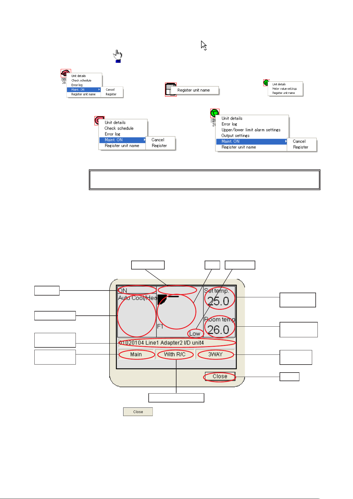
4-1-3-4-1. Indoor unit
Displays details of the operation status of the I/D unit.
Prohibition Flap Fan speed
Accumulated value
Analog point
ON/OFF
Operation mode
Address and
name
Main/sub
relationship
Set
temperature
Room
temperature
Associated
O/D unit
Close
With or without R/C
Click on the button to close the “Unit details” screen.
Page 18

4-1-3-4-2. Accumulated value
Displays the detail status of the accumulated value.
Address
and name
Adapter
value
Click on the button to close the “Accumulated value details” screen.
4-1-3-4-3. Digital point
Displays the detail status of the digital point.
Address and name
Status input condition
Alarm input condition
Status input address
Click on the button to close the “Digital point details” screen.
4-1-3-4-4. Analog point
Displays the detail status of the analog point.
Meter value
Internal output history
COS alarm condition
Alarm input address
ON/OFF output address
Address and name
Input point value
Output point value
Analog input point
Click on the button to close the “Analog point details” screen.
Analog output point
Input point low-limit
alarm value & status
Input point high-limit
alarm value & status
12 13
Page 19

4-1-3-5. Popup menu “Check schedule”
This menu is for indoor units and digital point (output) units.
It displays the operation schedule for the corresponding unit on the current date and
the next two days.
Click on the Check schedule in the popup menu to display the “Schedule” screen.
Address
Schedule
Click on the date on the “Schedule” screen to
show the “Detailed schedule” screen for the date
concerned, as illustrated on the right.
Click on the button to close the “Schedule” and
“Detailed schedule” screens.
Term
4-1-3-6. Popup menu “Error log”
This menu displays the error logs for I/D units, digital point, and analog point. Click
on the Error log in the popup menu to show the “Error log” screen.
Key
Alarm code : Displays alarm codes •
at the times alarms are
issued/restored.
Alarm date : Displays dates and times •
when alarms are issued/
restored.
Alarm : Displays occurrence/•
restoration status of
alarms.
Click on the button to close the “Error log”
screen.
Page 20

4-1-3-7. Popup menu “Maint. ON”
Indoor units, digital point, and analog point issue alarms. Alarms can be temporarily
suspended for mechanical work or device malfunctions. When you Register, alarm
will not be issued when an error occurs. When you Cancel, the alarm function is
restored. Start/stop control and alarm display are disabled for devices registered for
maintenance.
Click on the Maint. ON in the popup menu, then click on the Cancel or Register in the
sub-menu to specify Cancel or Register.
4-1-3-8. Popup menu “Name registration”
Use this menu to change names for any unit.
When the Password screen is displayed by
clicking the menu, enter (Password level
2). When the “Name registration” screen is
displayed, change the name.
After changing the name, click on the
button to change the name and
close the screen.
Click on the button to close the
screen without changing the name.
4-1-3-9. Popup menu “Meter value settings”
Use this menu to change the meter value in
the accumulated value. When the password
screen is displayed by clicking the menu,
enter (Password level 2).
When the “Meter value settings” screen is
displayed, change the Meter pulse count.
After changing, click on the
button to change the data.
Click on the button to restore
the data before the change.
Click on the button to close the
“Meter value settings” screen.
4-1-3-10. Popup menu “High/low-limit alarm settings”
Use this menu to change the high/low-limit alarm
value of the analog input. When the password
screen is displayed by clicking the menu, enter
(Password level 2).
When the “High/low-limit alarm settings” screen is
displayed, change the high-limit alarm value or lowlimit alarm value.
After changing, click on the button to
change the data and close the screen.
Click on the button to close the screen without changing the data.
14 15
Page 21

4-1-3-11. Popup menu “Output value settings”
Use this menu to change the output value of the
analog output. When the “Output value settings”
screen is displayed by clicking the menu, change
the Output value.
After changing, click on the button to
change the analog output value and close the
screen.
Click on the button to close the screen
without changing the value.
4-1-3-12. How to check the configuration of inddor units connected to an
outdoor unit
Click on an outdoor unit to display a configuration
list of all the connected indoor units. Modes and
operation status of connected indoor units can be
checked.
Key
Address : Displays the address numbers of •
indoor units.
Name : Displays the names of the indoor •
units.
Status : Displays ON, OFF, alarm and •
maintenance.
Mode : Displays the operation modes of •
indoor units.
Click on the button to close the “O/D unit” screen.
* For the operations of accumulated value, analog point, or digital point,
optional Distribution ratio software or Facility control software is required.
For more information, please contact your dealer or service provider.
Page 22

4-2. Layout Master
[Procedure]
Select Layout - Initial settings & maintenance - Layout master data from the menu
bar.
(Password level 1)
Layout master data can be used to allocate indoor unit and outdoor unit parts to layout displays
and make additions and deletions.
Parts list
Parts
Show/hide
Layout
diagram
selection and
specification.
: Displays a list of all registered parts.
: Displays or closes the Parts screen every time it is clicked.
* Bitmap files are usable as layout diagrams.
Contact your dealer or service provider about creating, altering or adding
bitmap files, and related operations.
16
Page 23

4-2-1. Registering layout diagrams
Register the positions of indoor units etc. to previously-created layout displays.
Registered
layout list
Layout
diagram
filename
Group name
(Building name
etc.)
Name (floor etc.)
Exit Start
registration
---------Select from registered items ---------
: Displays a list of registered layout diagrams.
---------Individual entry--------
: Displays the Select bitmap screen for selecting layout diagram
filenames.
: Displays the previously-registered Select group screen.
: Begins registration of indoor units etc. to the layout display.
: Closes the Layout master data.
17 18
Page 24

4-2-1-1. How to select registered layout diagrams
On the Layout diagram settings screen, click on the
button inside the Select from registered items
frame.
Display the List of registered items screen.
From the group names and
item names on the List of
registered items screen, click
to select the layout diagram
concerned. Selected items are
highlighted.
Click or double click on the
button to close the List
of registered items screen and
display the bitmap filenames,
group names and names for
the selected layout diagram on
the Layout diagram settings
screen.
Click on the button to switch to the
registration screens for indoor and outdoor units. Switch
to the screen for part allocation.
Click on the button to close the Layout
master data.
Page 25

4-2-1-2. How to select new layout diagrams
On the Layout diagram settings screen, click on the
Bitmap file name button inside the Individual
entry frame.
Display the Select bitmap screen.
* Layout diagrams cannot be created on this system.
Contact your dealer or service provider about
creating, altering or adding layout diagrams
(bitmap files), and related operations.
On the Select bitmap screen, clicking to select the
filename for the layout diagram to use highlights the
selected bitmap name.
Click or double click on the button to
close the Select Bitmap screen and display the
Bitmap file name on the screen.
Click on the button to exit without
doing anything.
The Layout diagram settings screen shows the situation
with the filename 'O_01F.BMP' selected.
* If the selected bitmap filename has already been set on
the Layout master data, the set name is displayed in the
Group name and Name columns.
19 20
Page 26

Input the group name.
If the group name has already been registered, click
on the button to display the Select group
screen. Click to select the name to use, then click
or double click on the button to exit file
selection, leaving the display as illustrated below.
If the group name is not registered, enter it directly
into the text box.
It will be registered as a new group name.
Input the name.
Use direct input.
Once name registration is complete, click on the
button to switch to the registration
screens for indoor units etc.
Click on the button to close the Layout
master data.
Page 27

Parts list
Parts
4-2-1-3. How to allocate parts to layout diagrams
Once selection is complete using 4-2-1-1. How to select registered layout diagrams
and 4-2-1-2. How to select new layout dagrams, click on the button to
switch the the Part Registration screen.
Parts
Show/ hide
Layout
: Displays a list of all registered parts.
: Displays or closes the Parts screen every time it is clicked.
4-2-1-4. The Parts List screen
Click on the button to display a list of the parts registered to the layout
diagram.
21 22
Page 28

4-2-1-5. The Parts screen
To allocate parts to the layout diagram, use the mouse to select them from the Parts
screen and release the mouse button where they are to be placed.
Part types
: Use this to select types of parts.
Part sizes
Part
selection
RegisterCancel
Click on the button to display a pulldown list and select
from that list.
: Specify the sizes of parts. Specify if parts are of the
same form but different sizes. Parts may not have been
registered if they are not required in the layout diagram.
: Select parts. Move the mouse pointer to the necessary
part and click on it. Drag the part with the mouse to the
where it should be placed. Release the mouse when the
part is in the right position.
(Placement is complete, so input the address.)
: Register the layout diagram and close the one you were
working on.
: Layout work finishes immediately and the layout diagram
closes. (The layout diagram is not registered)
Note: Normally, the Parts screen is displayed, but it may disappear when other
systems are used. In that case, click on the button to show
the Parts screen. The button can also be used to hide
the Parts screen. Repeated clicking toggles between showing and hiding the
screen.
Page 29

4-2-1-6. How to allocate parts to layout diagrams
To allocate and place parts, click on the relevant part on the Parts screen
to select it, then drag to move the part into position, leaving a part trail as
illustrated above.
Release the mouse when the part is in the correct position.
Coordinates are displayed while the part is being dragged with the mouse.
Click
and
drag
Once the mouse is released, a screen is displayed for entering the address of the part,
so enter the address.
After entering the address, click on the button or press the Enter key to
finish part placement.
Click on the button to cancel part placement.
* Addresses have eight digits for indoor units and six digits for outdoor units.
Check addresses in advance.
23 24
Page 30

4-2-1-7. How to move parts within layout diagrams
Click on the part to move.
The edge of the selected part is highlighted in red and its position
information is displayed, as illustrated on the left.
Either drag the part with the mouse or use the [] [] [] [] keys to move
it.
To stop moving the part, click on another part or on the button.
4-2-1-8. How to delete parts from layout diagrams
Click on the part to delete.
The edge of the selected part is highlighted in red and its position
information is displayed, as illustrated on the left.
Right click to display a query asking whether you want to delete the part.
Specify whether or not to delete it.
Click on the button to delete.
Click on the button to avoid deleting.
* When a layout diagram is deleted, it cannot be displayed.
Make a backup of the layout before proceeding.
* Even if the layout diagram is deleted, the master for indoor units and outdoor
units is not altered, so only the layout diagram becomes unavailable.
Page 31

4-2-1-9. How to delete layout diagrams
On the Layout diagram settings screen, click on the
button inside the Select from registered items
frame.
Display the List of registered items screen.
From “Group name/name
(Bitmap file name)“ on the List
of registered items screen,
click to select the layout
diagram concerned. Selected
items are highlighted.
Click on the button
to display the Check deleted
layout data screen.
On the Check deleted layout data screen,
display the group name, name and file name
and confirm their deletion.
Click on the button to delete.
Click on the button to avoid
deleting.
Once you click on the
button to delete,
the deletion is applied to
the Layout diagram settings
screen and you can give the
next instruction.
Click on the button
to close the Layout diagram
settings screen.
25
Page 32

4-3 Settings
[[Procedure]
Select Layout - Initial settings & maintenance - Settings from the menu bar.
(Password level 1)
Settings can choose whether or not the display should jump to the affected screen when an alarm is
issued, and whether or not to display set temperature, room temperature, facility control (analog data),
and accumulated (pulse) value.
Specifies whether or not to display the layout screen of
the affected unit when an alarm is issued
Specifies whether or
not to display the set
temperature
Specifies whether
or not to display
the room
temperature
Specifies whether
or not to display the
analog output value
Specifies whether
or not to display the
adapter value
: Registers settings and close the “Layout diagram settings” screen.
: Closes the “Layout diagram settings” screen with no other action.
* For “Facility Control” operations, optional Facility control software is
required. If this optional software is not installed, this option cannot be
selected.
* For “Accumulation (pulse)” operations, optional Distribution ratio software
is required. If this optional software is not installed, this option cannot be
selected.
For more information, please contact your dealer or service provider.
Specifies whether
or not to display the
analog input value
Specifies whether
or not to display the
meter value
26 27
Page 33

4-4. Layout backup
[Procedure]
Select Layout - Initial settings & maintenance - Layout Backup
from the menu bar.
(Password level 2)
Make backups of layout information. The initial file name is automatically set to the numbers for
"yyyymmdd_hhmm" with "laybak" as the extension.
:Make backups of layout information.
:Exit.
:Use to change the save folder.
4-4-1. Starting layout information backup
Click on the button to backup layout information.
Save backup data.
Once the backup is complete, a message
such as that on the left is displayed. Click
on the button. The data
backup process ends.
* The message on the right is displayed if the
backup fails. Check the available free space
on the backup storage drive, etc.
Click on the button to go back
to Layout information backup.
Page 34

4-4-2. Deleting layout information backups
Click on the button to exit without saving the backup data.
4-4-3. Changing the save location for layout information backups
Click on the button to display the "Backup file name" screen and
change the save folder.
Click on the button beside "Save in" to display a folder list as illustrated below.
Select the required folder from the folder list.
Click on the button to apply the selected
save destination and return to the Layout information
backup screen.
Click on the button to return to the
Layout information backup screen without doing
anything.
28 29
Page 35

4-5. Restoring layouts
[Procedure]
Select Layout - Initial settings & maintenance - Layout restore
on the menu bar.
(Password level 2)
Use the file created at the Layout Backup stage to return the layout to its state at the time of the
backup.
: Click on the relevant filename and specify the file name displayed under
"File name".
: Exit without doing anything.
When layouts are restored, current layout information is lost.
If you need to retain current information, use Layout information backup in
advance to backup layouts.
Page 36

4-5-1. Starting layout restoration
On the "Select backup file to restore" screen, click on the file name to restore.
The specified file name is displayed in the "File name" space, then click on the
button.
The Restore layout information screen is displayed.
:Restore the layout information.
:Exit.
:Use this when you need to specify a different backup file.
4-5-1-1. Starting layout restoration
To start layout restoration, click on the button. A message reading
"When restore is complete ..." is displayed.
Click on the button to
return to the Restore layout information
screen.
Click on the button to
start the restoration process.
Once the restoration is complete, a message
such as that on the left is displayed.
Click on the button.
The P-AIMS system exits automatically.
Restart the P-AIMS system.
The layout restoration process ends.
30 31
Page 37

4-5-1-2. Canceling layout restoration
Click on the button to exit without restoring layouts.
4-5-1-3. Re-specifying the layout restoration file
Click on the button to re-display the "Select backup file to restore"
screen.
Page 38

5. Supplementary Information
Layout diagrams
The layout diagrams used by the P-AIMS System must be drawn up to match the customer's
layout, but they cannot be created using this system. For more information about layout
creation, contact your dealer or service provider.
Part icons
Part icons for use with the P-AIMS System are provided in advance for standard parts as
shown in [Reference] Parts list at the end of this manual.
Part icons other than shown in the parts list must be provided separately if necessary. These
part icons cannot be created using this system. For more information about their creation,
contact your dealer or service provider.
Personal Computers
Use a personal computer exclusively for the P-AIMS System.
Sharing the PC with any other system could cause problems.
Data backup
The PC used with the P-AIMS System could break down, so you are advised to back up data to
an external hard drive or other storage. For more information, contact your dealer or service
provider.
Caution: If the drive name of the external hard disk or other backup location changes, backups
cannot be done.
NOTE: When the drive name of an external hard disk drive is changed, it is not possible to
back up.
Power outages
We recommend use of a UPS device (uninterruptible power supply) to protect the P-AIMS
System in the event of a power outage. For more information, contact your dealer or service
provider.
Please note that we will not provide compensation in the following circumstances:
Any fault caused by a third party becoming aware of a password.
Any fault caused by sharing a PC between P-AIMS System and another application.
Limitations on changing settings
Some types of air conditioners are limited in the settings which they support.
For example, cooling-only air conditioners cannot be set to heating.
Floor-type models typically support only high fan speeds.
Ceiling mounted models do not have flaps, and therefore cannot change the fan direction.
You should be aware of the limitations of the air conditioner models in your system.
For more information, contact your dealer or service provider.
Only alarm codes are displayed in the notification bar and alarm log display.
The content of an alarm can vary for different models, even if the alarm code is the same.
Consult the documentation of the various models to determine the content of the alarm.
After the settings of an indoor unit are changed from the P-AIMS System, the display may
revert temporarily to the former settings.
This is more likely to occur with all-unit operations. The cause is communications delay, not
any malfunction in the system. If you wait a few minutes, the display will show the correct
information.
32 33
Page 39

If an electrical storm, radio transmissions or other interference during operation caused a
malfunction, turn the terminal power off, then on again.
As a rule, the system should be powered off only in cases such as the above.
Correct management of air conditioning is not possible when the system is powered off.
Setting the current date and time
The current date and time should be set on a regular basis, since the clock of an ordinary PC
can gain or lose up to about two minutes per month.
Passwords
Passwords should be recorded and saved in a safe place. They should never be disclosed to
third parties.
If you forget your password, contact your dealer or service provider.
Page 40

6. License Certification
Before you can use the Layout Display Software, you need to first perform a work procedure
called "license certification."
To perform license certification, make an inquiry by sending the inquiry key to the inquiry e-mail
address below. You will be registered as a user and issued a release key, and then receive a
reply.
<Contact Information>
Product ID Issuance Desk,
E-mail address: cmc_productid_desk@gg.jp.panasonic.com
When you make an inquiry, send the following information together with the inquiry in order to
be registered as a user and issued a release key.
(1) Product name
(2) Company name/contact person
(3) Phone number
(4) E-mail address
(5) Inquiry key
* If you do not input a release key, you will no longer be able to use the system after 30 days
elapses. Obtain a release key and perform license certification as soon as possible.
* Make an inquiry as soon as possible because it may sometimes take several days to be
issued a release key.
License Certification Procedure
The procedure from after the P-AIMS system is installed up until the end of license
certification is described below.
(1) Check the inquiry key from the License Certification screen.
(2) Send the inquiry key to the Product ID Issuance Desk (cmc_productid_desk@gg.jp.
panasonic.com).
Also notify us of the product name, company name/contact person, phone number,
and e-mail address.
(3) A release key is issued.
You are registered as a user and a release key is issued. A reply is sent to the
registered mail address.
(4) Input the release key from the License Certification screen.
(5) The license certification procedure is finished.
34 35
Page 41

Performing License Certification
1. A License Certification screen such as the following appears when you start a P-AIMS systems
for which license certification is not finished.
"Layout Display Software (25)" means that the
number of remaining days that you can use
the Layout Display Software is "25." It is not
displayed after you finish license certification.
* After you start a P-AIMS system for which license certification is not finished, the License
Certification screen will appear at 9:00 a.m. and 3:00 p.m. This screen is not displayed after
you finish license certification.
If you install optional software, the License Certification screen will appear until license
certification is finished for all of the software.
: Clicking this button saves the inquiry key as a text file. Follow the instructions
on the screen to save the text file. Enter the product name, company name/
contact person, phone number, and e-mail address in this saved text file, and
send the text file to the Product ID Issuance Desk by e-mail.
:Clicking this button copies the inquiry key to the Windows clipboard. Paste the
inquiry key into your mail.
:Clicking this button closes the Inquiry Key display screen.
2. If you click the
button in the License Certification
screen, the Inquiry Key display
screen appears, and the inquiry key is
displayed in the screen.
Send the key displayed in this screen
to the Product ID Issuance Desk (cmc_
productid_desk@gg.jp.panasonic.com)
by e-mail.
At the same time, also notify us of the
following items.
(1) Product name (required)
(2) Company name/contact person
(3) Phone number
(4) E-mail address (required)
You will be registered as a user and
issued a release key.
Page 42

3. When you receive the release key,
restart the P-AIMS system. See “2.
Startup and exit“ for how to restart the
P-AIMS system, and then restart the
system.
If license certification is not finished
for the P-AIMS system, the License
Certification screen on the right appears
before the P-AIMS system restarts.
Click the button to
display the Release Key input screen,
and enter the release key.
* If you install multiple P-AIMS system software, the same number of license certifications is
required. In such a case, the number of release keys sent will be the same as the number of
inquiry keys.
Enter all of the received release keys sequentially, and perform license certification. (There is
no set order for entering release keys, so they can be entered in any order.)
License certification is finished once all of the release keys have been entered.
Click the button. The License Certification screen closes, and the P-AIMS
system starts.
* The P-AIMS system will start even if you click the button without entering
the release key. You can use the system as is until license certification is finished. (The
system can be used for a period of 30 days.)
36 37
Page 43

7. Preparation
7-1. Installation
1. First, stop the P-AIMS system.
Insert the Layout Display Software
CZ-CSWGC2 CD of the air-conditioning
integrated system (P-AIMS system)
you purchased into the CD-ROM drive.
The program on the CD-ROM starts
automatically and makes preparations
for installation. If installation does not
start, double-click Setup.exe of the CDROM drive to start it.
Enter the Product ID in the Input Product
ID screen that appears.
For the Product ID, see the Product ID
Issuance Certificate supplied with the
software.
* Keep the Product ID Issuance
Certificate in a safe place. The Product
ID is required to install the airconditioning integrated system. The
Product ID Issuance Certificate will not
be reissued.
2. The InstallShield Wizard prepares to
install the P-AIMS system.
3. After a short while, the "The
InstallShield(R) Wizard will install
P-AIMS Layout Display Option on your
computer. To continue, click Next.”
message appears. Click the
button.
Page 44

4. Next, the License Agreement screen
appears. Carefully read the license
agreement, and click "I accept the terms
in the license agreement" if you agree
to the terms of the license agreement.
The button becomes active.
Click the button. (The
software cannot be installed if you do
not agree to the terms of the license
agreement.)
5. The “The wizard is ready to begin
installation. Click Install to begin the
installation.” message appears. Click
the button.
6. The installation of the P-AIMS system
begins.
Please wait a while.
7. When the P-AIMS system setup is
finished, the installation complete
screen appears.
Click the button to complete
the installation.
* When installing the Layout Display software, it is possible to install this system without
stopping the P-AIMS system, but the functions of the Layout Display software will not be
added. Restart the P-AIMS system.
38 39
Page 45

7-2. Display after restart
After the system restarts, the layout display function is enabled and the menu item
Layout is selectable.
7-3 Settings
Once installation is complete, settings are required for "Layout diagram preparation",
"Indoor unit settings", "Outdoor unit settings", etc. Refer to the explanations in the
corresponding sections for information on these settings.
* Contact your dealer about "Layout diagram preparation".
Page 46

[Reference] Parts list
Indoor unit
:
Unidirectional ceiling
cassette
: 4-directional ceiling
cassette
: Bidirectional ceiling
cassette
: Ceiling built-in
cassette
: Ceiling suspended : Wall mounted : For kitchen use
: Perimeter, floor
standing
: Built-in, all ducts : Ceiling-embedded,
: Floor standing
Outdoor unit
:
Single
:
GHP
:
Single
:VRF
Accumulated value (optional Distribution ratio software is required)
high static pressure
:GHP
:Watt meter :Gas meter :Water meter
Digital point (optional Facility control software is required)
:Fan :Pump :Illumination
Analog point (optional Facility control software is required)
: Centigrade
temperature
: Voltage
:Percentage :Current
: Fahrenheit temperature
40
Page 47

Page 48

User memo space
If you fill this out at the time of purchase, it is convenient when ordering repairs etc.
Serial No.
Date of installation
Dealer
Telephone No. ( )
Page 49

Authorized representative in EU
Panasonic Testing Centre
Panasonic Marketing Europe GmbH
Winsbergring 15, 22525 Hamburg, Germany
85464609113001
Printed in Japan
 Loading...