

Page 1
E
N
G
L
I
S
H
47
CY-VMD9000U
62
Installation Guide
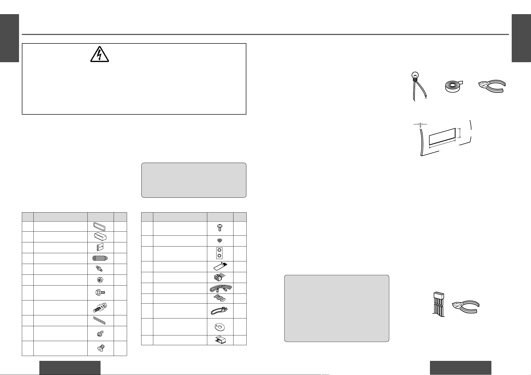
WARNING
This installation information is designed for experienced installers and is not intended for non-technical individuals. It does not contain warnings or cautions of potential
dangers involved in attempting to install this product.
Any attempt to install this product in a motor car by anyone other than qualified
installer could cause damage to the electrical system and could result in serious personal injury or death.
❐ Installation Hardware
❐ Overview
This product should be installed by a professional.
However, if you plan to install this unit yourself, your
first step is to decide where to install it. The instructions in these pages will guide you through the
remaining steps:
(Please refer to the “WARNING” statement
above.)
≥ Identify and label the car wires.
≥ Connect the car wires to the wires of the power
connector.
E
N
G
L
I
S
H
48
CY-VMD9000U
63
12 V DC test
bulb
Electrical tape Slide-cut
pliers
❐ Required Tools
You’ll need a screwdriver and the following:
❐ Before Installation
Warning
≥ Do not install the monitor in a location which
obstructs driving, visibility or which is prohibited by applicable laws and regulations.
If the monitor is installed in a location which
obstructs forward visibility or operation of the air
bag or other safety equipment or which interferes
with operation of the car, it may cause an accident.
≥ Never use bolts or nuts from the car’s safety
devices for installation.
If bolts or nuts from the wheel, brakes or other
safety devices are used for installation of the monitor, it may cause an accident.
≥ Attach the wires correctly.
If the wiring is not correctly performed, it may
cause a fire or an accident. In particular, be sure to
run and secure the lead wire so that it does not get
tangled with a screw or the moving portion of a
seat rail.
≥ Use with 12 V DC negative ground car.
This unit is only for use with a 12 V DC negative
ground car. It cannot be used in large trucks or
diesel cars which are 24 V DC cars. If it is used in
the wrong type of car, it may cause a fire or an
accident.
Caution:
≥ This unit operates with a 12 V DC negative
ground auto battery system only. Do not
attempt to use it in any other system. Doing
so could cause serious damage.
Cautions:
≥ Use the specified fuse.
Be sure to always use the specified fuse. If a
fuse other than the specified fuse is used, it
may cause a fire or an accident.
≥ Do not damage the cord by pinching or
pulling it.
Do not pull or damage the cord. If the cord is
not treated properly, it will short out or be
severed and may cause a fire or an accident.
≥ Install the unit in the dashboard.
≥ Check the operation of the unit.
If you encounter problems, please consult your
nearest professional installer.
Before you begin installation, look for the following
items which are packed with your unit.
≥ Warranty Card…Fill this out promptly.
≥ Panasonic Servicenter List for Service Directory
…Keep for future reference in case the unit needs
servicing.
≥ Installation Hardware…Needed for monitor set-
ting.
❐ Dashboard Specifications
The first step in installation is to identify all the car
wires you’ll use when hooking up your LCD monitor.
As you identify each wire, we suggest that you label
it using masking tape and a permanent marker. This
will help avoid confusion when making connections
later.
Note:
≥Do not connect the power connector to the display
unit until you have made all connections. If there
are no plastic caps on the hooking wires, insulate
all exposed leads with electrical tape until you are
ready to use them. Identify the leads in the following order.
Power Lead
If your car has a radio or is pre-wired for one:
Cut the connector wires one at a time from the plug
(leaving the leads as long as possible) so that you
can work with individual leads. Turn the ignition on
to the accessory position, and ground one lead of
the test bulb to the chassis.
❐ Identify All Leads
No. Item Diagram Q’ty
1 Trim plate 1
2 Mounting collar 1
3 Mounting spring 2
4 Rubber pad 1
5 Mounting bolt (M5) 1
6 Flange nut (M6) 1
7 Washer assembling hex.
bolt (M5k10 mm)
1
8 Washer assembling hex.
bolt (M6k20 mm)
1
9 Rear support strap 1
: Binding-head screw
(M5k6 mm)
2
; Flat-head screw
(M5k6 mm)
4
No. Item Diagram Q’ty
< Binding-head screw
(M4k3 mm)
4
= Spacer 2
> Double-faced adhesive 1
tape (for spacer) set
? Velcro tape 2
@ Power connector 1
A Reverse extension cord 1
B Clip connector 1
C Display unit/control unit
connecting cord
1
D Double-faced adhesive
tape (for speaker)
1
E Clamp 2
Thickness
Min. 3/16q (4.75 mm)
Max. 7/32q (5.56 mm)
23/32q (53 mm)
75/32q (182 mm)
Touch the other lead of the test bulb to each of the
exposed wires from the cut radio connector plug.
Touch one wire at a time until you find the outlet that
causes the test bulb to light.
Now turn the ignition off and then on. If the bulb also
turns off and on, that outlet is the car power lead.
Page 2
E
N
G
L
I
S
H
50
CY-VMD9000U
65
E
N
G
L
I
S
H
49
CY-VMD9000U
64
Installation Guide (Continued)
If your car is not wired for an audio unit:
Go to the fuse block and find the fuse port for radio
(RADIO), accessory (ACC), or ignition (IGN).
Battery Lead
If your unit has a yellow lead, you will need to locate
the car’s battery lead. Otherwise you may ignore this
procedure. (The yellow battery lead provides continuous power to maintain a clock, memory storage, or
other functions.)
If your car has a radio or is pre-wired for one:
With the ignition and headlights off, identify the car
battery lead by grounding one lead of the test bulb to
the chassis and checking the remaining exposed
wires from the cut radio connector plug.
If your car is not wired for an audio unit:
Go to the fuse block and find the fuse port for the
battery, usually marked BAT.
❐ Connect All Leads
Now that you have identified all the wires in the car,
you are ready to begin connecting them to the LCD
monitor wires. The wiring diagram (➡ pages 70, 71)
shows the proper connections and color coding of
the leads.
We strongly recommend that you test the unit
before making a final installation.
You can set the unit on the floor and make temporary connections to test the unit. Use electrical tape
to cover all exposed wires.
Important:
≥Connect the red power lead last, after you have
made and insulated all other connections.
Ground
Connect the black ground lead of the power connector to the metal car chassis.
Battery
Connect the yellow battery lead to the correct radio
wire or to the battery fuse port on the fuse block.
Equipment
Connect any optional equipment according to the
instructions furnished with the equipment. Read the
operating and installation instructions of any equipment you will connect to this unit.
Power
Connect the red power lead to the correct car radio
wire or to the appropriate fuse port on the fuse
block.
If the LCD monitor functions properly with all these
connections made, disconnect the wires and proceed to the final installation.
❐ Final Installation
Lead Connections
Connect all wires, making sure that each connection
is insulated and secure. Bundle all loose wires and
fasten them with tape so they will not fall down later.
Now insert the LCD monitor into the mounting collar.
Congratulations! After making a few final checks,
you’re ready to enjoy your new LCD monitor.
❐ Final Checks
1. Make sure that all wires are properly connected
and insulated.
2. Make sure that the LCD monitor is securely held
in the mounting collar.
3. Turn on the ignition to check the unit for proper
operation.
If you have difficulties, consult your nearest authorized professional installer for assistance.
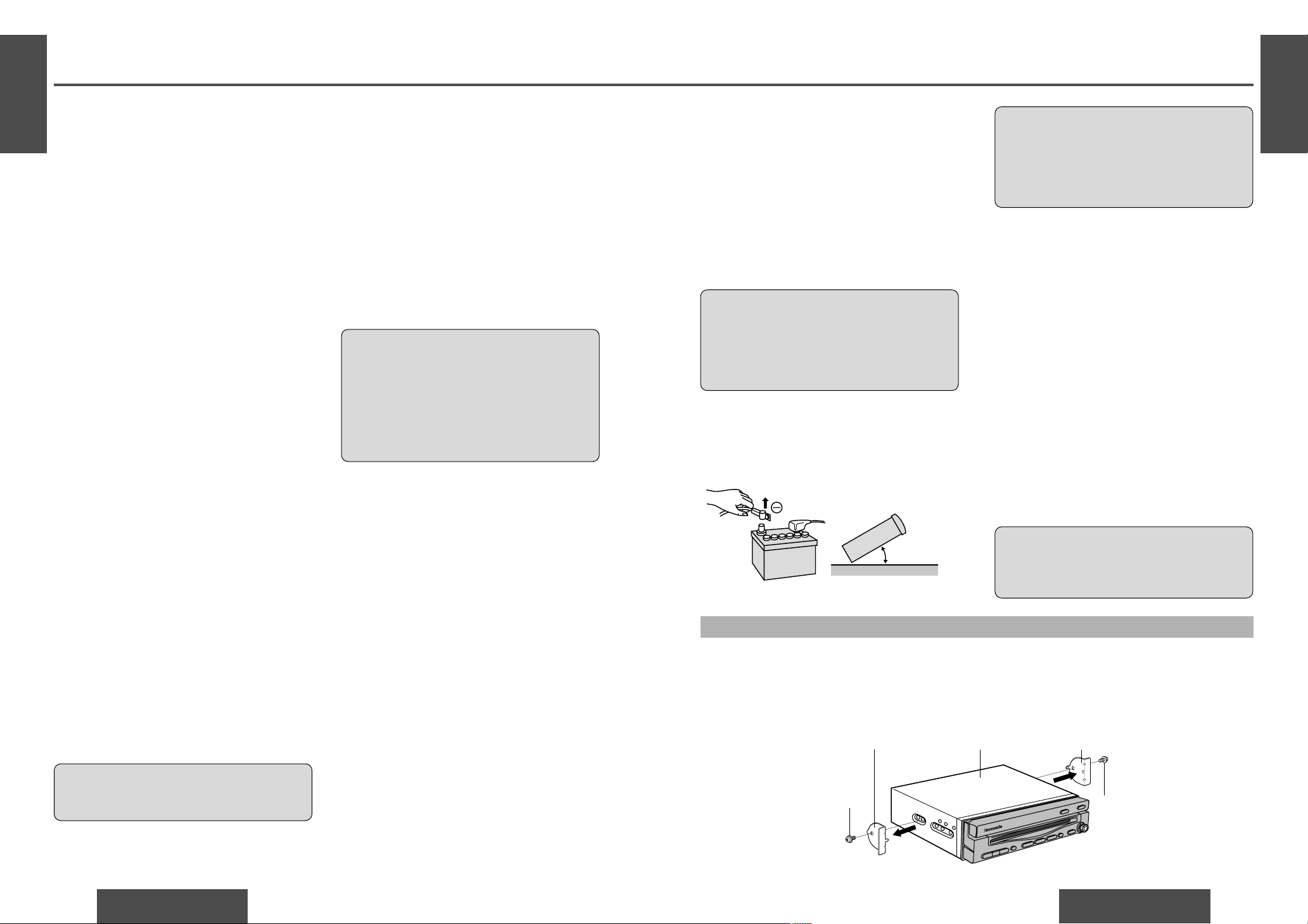
❐ Preparation
≥We strongly recommend that you wear gloves
for installation work to protect yourself from
injuries.
≥When bending the mounting tabs of the mount-
ing collar with a screwdriver, be careful not to
injure your hands and fingers.
≥Disconnect the cable from the negative -battery
terminal (see caution at right).
≥Unit should be installed in a horizontal position
with the front end up at a convenient angle, but not
more than 30o.
Caution:
≥Do not disconnect the battery terminals of a car
with a trip or navigational computer since all
user settings stored in memory will be lost.
Instead take extra care with installing the unit
to prevent shorts.
Less than 30x
This unit should be professionally installed. In case
of difficulty, please consult with your nearest professional installer.
1. This unit only operates in a 12 V DC negative
ground system.
2. Follow the electrical connections carefully
(➡ pages 70, 71). Failure to do so may result in
damage to the unit.
3. Connect the power connector after all other connections are made.
4. Be sure to connect the battery lead (yellow) to the
positive terminal (+) of the battery or fuse block
(BAT) terminal.
5. Insulate all exposed wires to prevent short circuiting.
6. Secure all loose wires after installing the unit.
7. Please carefully read the operating and installation instructions of the respective equipment
before connecting it to this unit.
Caution:
≥Please follow the laws and regulations of your
state, province or country for installation of the
unit.
Mounting the Display Unit
❐ Transportation bracket removal
Be sure to remove the transportation brackets before use (installation) and keep them for the future.
Use binding-head screws (M5k6 mm) for installation. (➡ page 68)
Be careful not to lose these binding-head screws.
Display unitTransportation bracket
Binding-head screws
(M5a6 mm)
Binding-head screws
(M5a6 mm)
Transportation bracket
Speakers (not supplied speaker)
Identify the car speaker leads. There are two leads
for each speaker, usually color coded.
A handy way to identify the speaker leads and the
speaker they are connected with is to test the leads
using a 1.5 V AA battery as follows.
Hold one lead against one pole of the battery and
stroke the other lead across the other pole. You will
hear a scraping sound in a speaker if you are holding
a speaker lead.
If not, keep testing different lead combinations until
you have located all the speaker leads. When you
label them, include the speaker location for each.
Speakers (not supplied speaker)
Connect the speaker wires. See the wiring diagram
for the proper hookups. Follow the diagram carefully to avoid damaging the speakers and the stereo
unit.
The speakers used must be able to handle more than
45 W of audio power. If using an optional audio
power, the speakers should be able to handle the
maximum amplifier output power. Speakers with
low input ratings can be damaged.
Speaker impedance should measure 4–8 ≠, which
is typically marked on most speakers. Lower or
higher impedance speakers will affect output and
can cause both speaker and stereo unit damage.
Caution:
≥Never ground the speaker cords. For example,
do not use a chassis ground system or a threewire speaker common system. Each speaker
must be connected separately using parallel
insulated wires. If in doubt about how your
car
’s speakers are wired, please consult with your
nearest professional installer.
Page 3
E
N
G
L
I
S
H
52
CY-VMD9000U
67
E
N
G
L
I
S
H
51
CY-VMD9000U
66
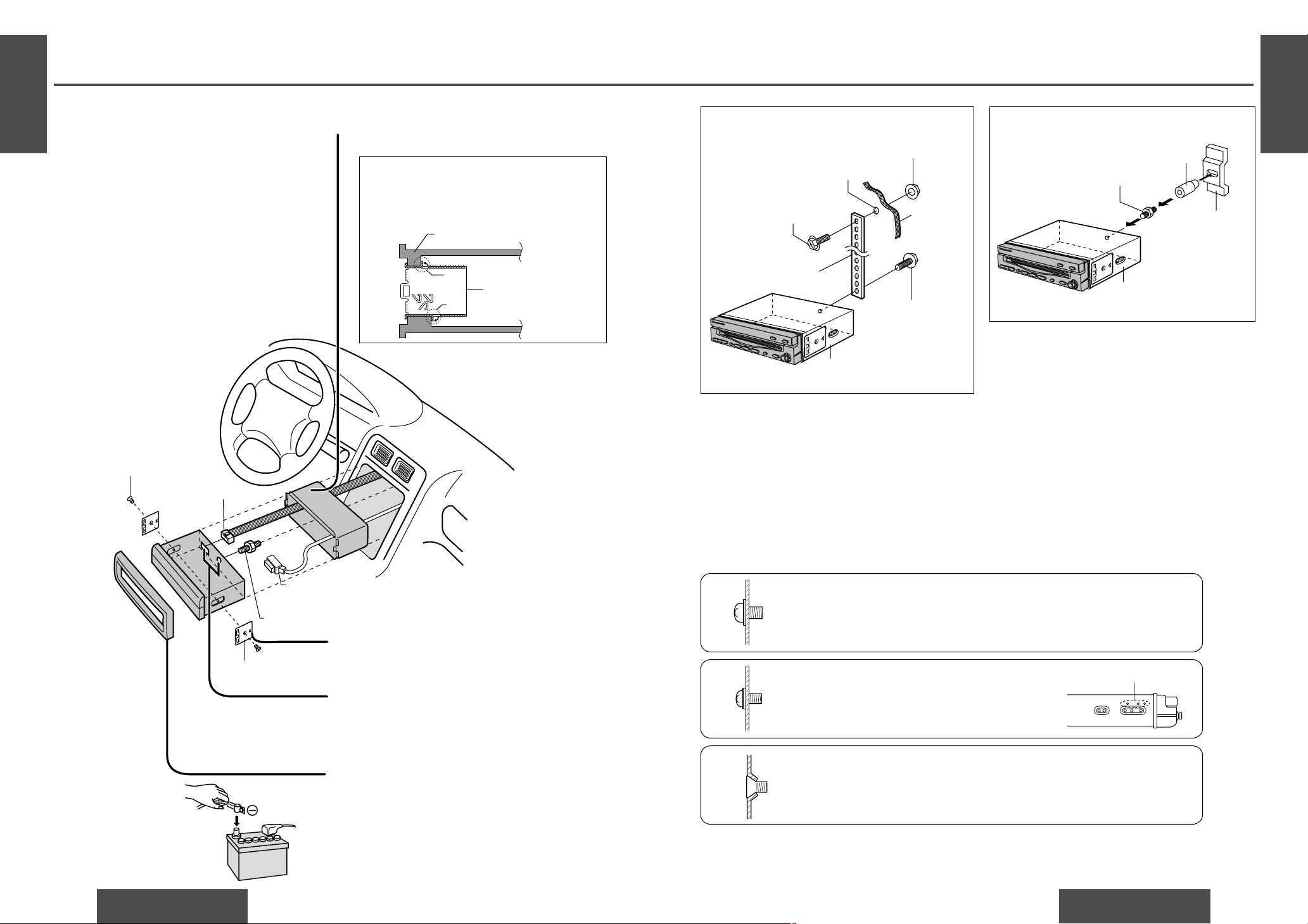
Installation Guide (Continued)
❐ Installation Procedures
(When using mounting collar 2)
(a) Using the rear support strap 9
Drill a hole 6.5 to 7 mm in diameter.
9 Rear support strap
7 Washer assem-
bling hex. bolt
(M5a10 mm)*
1
6 Flange nut (M6)
Fire wall
of car
(b) Using the rubber pad 4
5 Mounting bolt (M5)
Bracket (on car)
Display unit
4 Rubber pad
8 Washer assembling
hex. bolt (M6a20 mm)
Use the brackets supplied with your car when mounting this unit. The bracket shape and mounting method
vary with car manufactures, car types and manufacturing year.
Please consult your nearest your nearest Panasonic Servicenter for details.
Select mounting screws according to the hole positions and hole shape of the bracket.
: Binding-head screw (M5k6 mm)
2 pieces
Recycle the binding-head screws that fixed the transportation brackets for
two more positions.
;
Flat-head screw (M5k6 mm)
3
Mounting spring
5
Mounting bolt (M5)
C
@
Power connector
Display unit/control unit
connecting cord
Tab
Tab
Dashboard
Mounting collar
2
Fastening the mounting collar
The tabs to be bent vary depending on the car.
Bend them with a screwdriver to fasten the
mounting collar 2 securely in the dashboard.
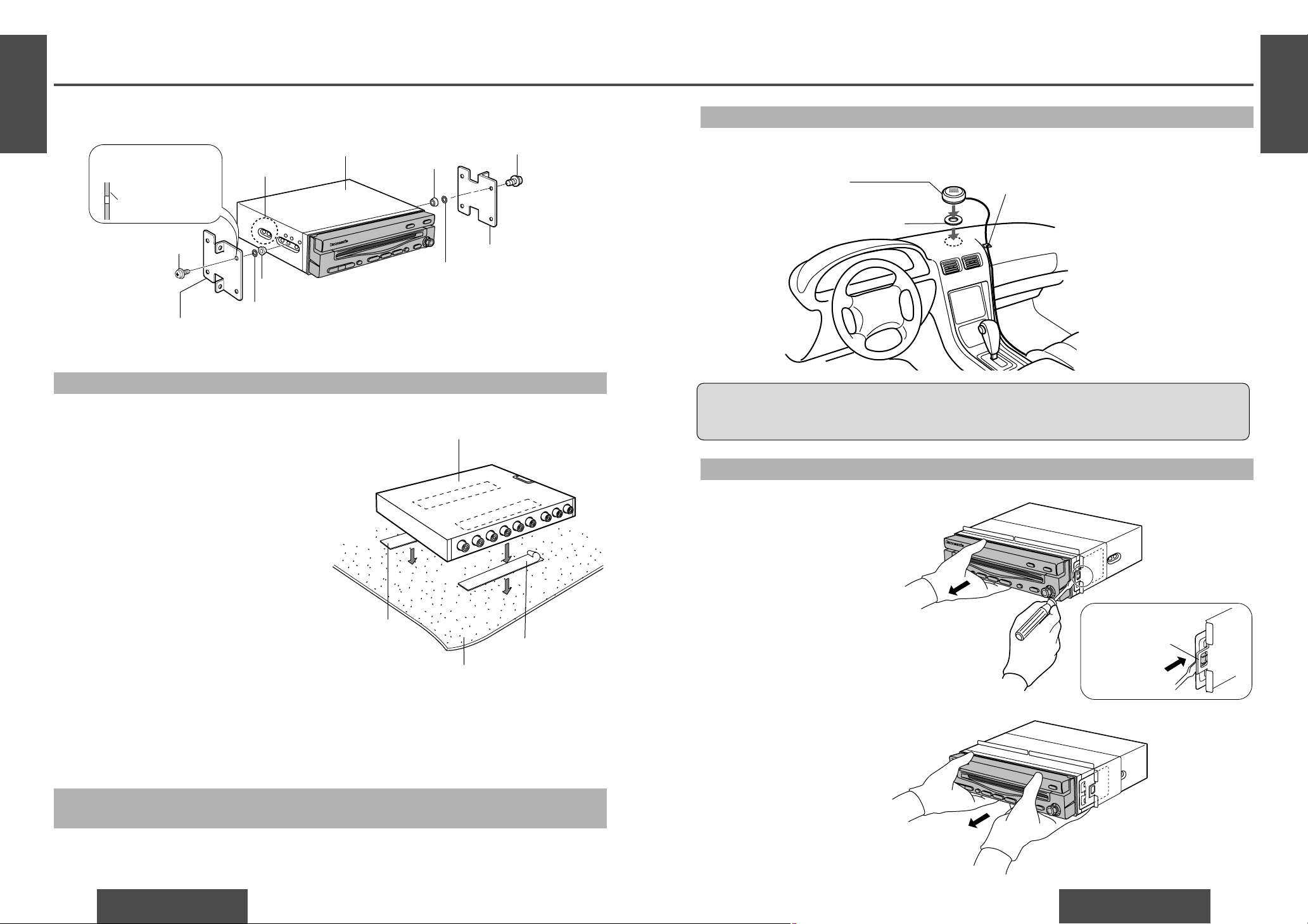
❐ Installation Procedures
(When not using mounting collar 2)
< Binding-head screw (M4k3 mm)
4 pieces
; Flat-head screw (M5k6 mm)
4 pieces
When using these mounting holes
Insert mounting collar 2 into the dashboard,
and bend the mounting tabs out with a screwdriver.
1
Insert trim plate 1.
After installation, reconnect the negative - battery terminal.
4
5
Attach the mounting springs 3 to the display
unit.
2
Secure the rear of the unit.
After fixing power connector @and display
unit/control unit connecting cord C, fix the rear of
the unit to the car body by either method (a) or (b)
shown at right.
3
Display unit
Side of the display unit
Note:
≥ The car model, installation conditions and
combination of the units used may impose
some restrictions on opening and closing the
monitor as well as on the angle and position
to which the monitor can be adjusted.
*
1
Use M5a8 mm size bolts (optional) if bolts other than the supplied ones are to be used.
Page 4
E
N
G
L
I
S
H
54
CY-VMD9000U
69
E
N
G
L
I
S
H
53
CY-VMD9000U
68
Installation Guide (Continued)
Mounting the Control Unit
Mounting the Speaker (Supplied)
Removing the Display Unit
❐ Mounting Example
Before mounting the unit, wipe a drop of water, dust
and an oil stain off from the place where the unit
should be mounted to enhance velcro strength.
Stick velcro tape ? on the carpet (underneath the passenger seat, etc.) and mount the control unit on it.
Note:
≥Some carpet materials may not be suitable for this
mounting method. In this case, please contact your
nearest Panasonic Servicenter for installation.
Notes:
≥Never mount the control unit in any of the following locations to avoid damage due to overheating:
• Near the heater port.
• Places like the dashboard or rear deck, where it may be exposed to direct sunlight.
≥Do not mount the control unit near the door, where it could be exposed to rain.
Before mounting the speaker, wipe a drop of water, dust and an oil stain off from the place where the speaker
should be mounted to enhance adhesive strength.
Cautions:
≥Do not install the speaker in a location which obstructs operation of the air bag or other safely equipment.
≥Do not leave a credit card or other magnetic cards near the speakers to avoid damaging the cards.
Push the right and left clamp plates outward, one
at a time, and pull the display unit toward yourself.
Use the supplied spacer = if mounting hole of your car is shaped like below.
Mounting hole of a
bracket (in section)
Bracket
Not used.
Display unit
= Spacer
: Binding-head screw
(M5a6 mm)
Existing bracket (L)
(Bracket originally attached to the car.
The exterior design differs from that of the actual product.)
= Spacer
> Double-faced adhesive tape
> Double-faced adhesive tape
Existing bracket (R)
: Binding-head screw
(M5a6 mm)
Control unit
? Velcro tape
? Velcro tape
Carpet
Speaker (supplied)
≥Cannot be used for a center speaker.
D Double-faced adhesive tape
E Clamp
After removing the right and left clamp plates, pull
the unit with both hands till it comes off.
Push here to remove
the clamp plates.
1
2
Mounting the AV Control Unit with Receiver (CA-TU7000U) or
Multi Channel AV Control Unit with Receiver (CA-TU9000U)
Refer to the operating instructions of the AV control unit with receiver (CA-TU7000U) or multi channel AV control unit with receiver (CA-TU9000U).
Page 5
E
N
G
L
I
S
H
56
CY-VMD9000U
71
E
N
G
L
I
S
H
55
CY-VMD9000U
70
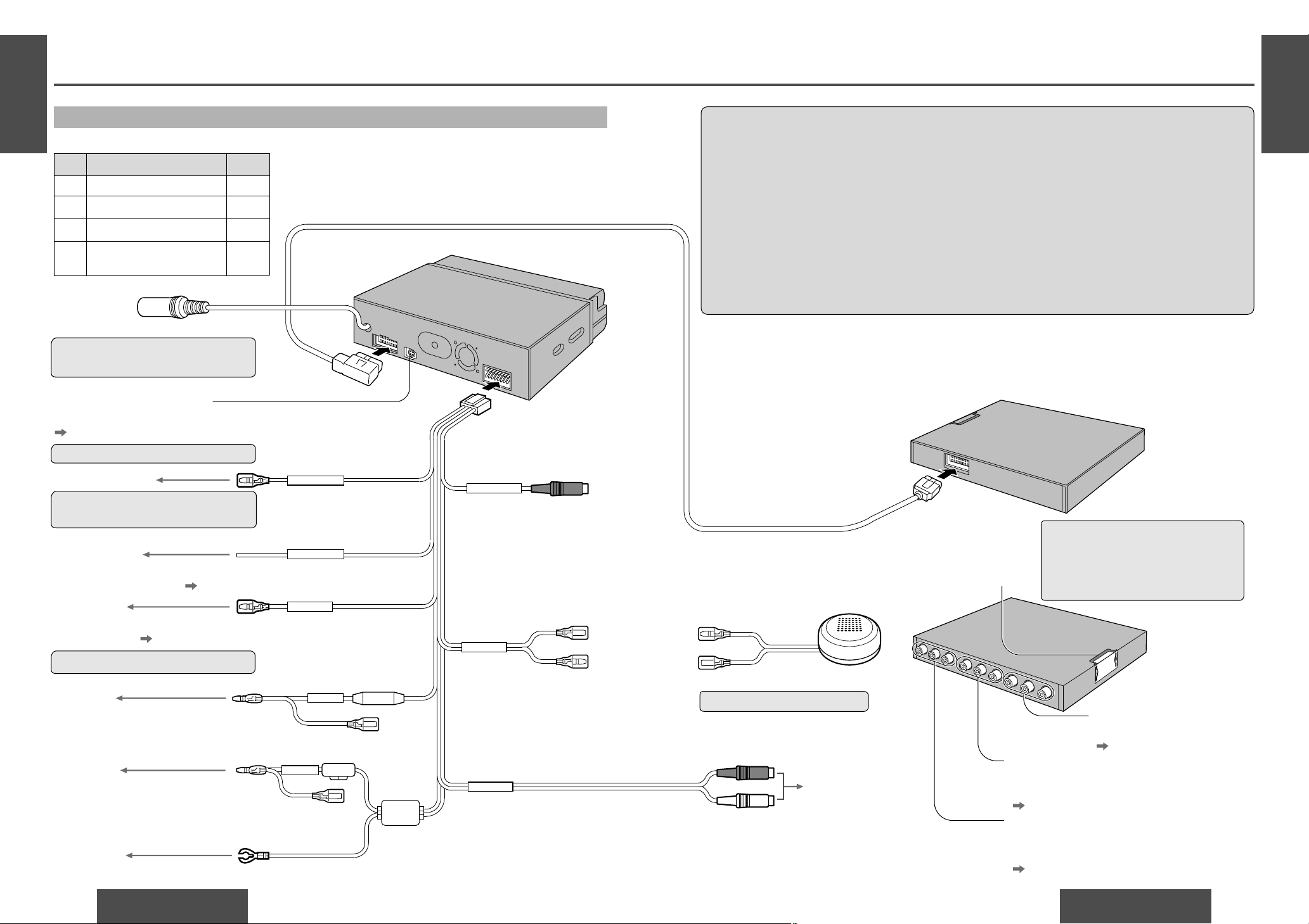
Electrical Connections
Wiring Diagram
Cautions:
≥ This unit is designed to operate off a 12 V DC, negative ground battery system.
≥ To prevent damage to the unit, be sure to follow the connection diagram below.
≥ Remove approximately 1/4q (5 mm) of protective covering from the ends of the leads before connecting.
≥ Do not insert the power connector into the unit until the wiring is completed.
≥ Be sure to insulate any exposed wires from a possible short-circuit from the car chassis. Bundle all
cables and keep cable terminals free from touching any metal parts.
≥ Note that if your car has a driving computer or a navigation computer, disconnecting the battery cables
may cause the contents of memory for these computers to be lost.
≥ The side brake (parking brake) connection lead should be connected by a professional installer. In case
of difficulty, please consult your nearest authorized Panasonic Servicenter.
≥ All other installation methods require the use of dedicated metal fittings. Consult with a qualified servic-
ing engineer or your dealer if other methods are required.
Power connector
Video control lead
Digital signal output terminal
Connect the multi channel AV control unit with receiver (CA-TU9000U).
( See the operating instructions of the CA-TU9000U.)
Connector
Connect AV control unit with receiver (CA-TU7000U)
or multi channel AV control unit with receiver (CA-TU9000U).
R (Red)
L (White)
Reverse lead
When connecting the rear view camera,
use the reverse lead. ( page 79)
Use a reverse extension cord if needed.
You need the optical fiber cable (sold separately).
Cannot be used for a center speaker.
Leave the cover unremoved if you
do not connect AV control unit with
receiver (CA-TU7000U) or multi
channel AV control unit with receiver
(CA-TU9000U).
Side brake (parking brake)
connection lead
Be sure to wire the side brake (parking brake) for
safety and preventing accidents. ( page 78)
To the input terminat of
the auxiliary system.
Pre-out cord
Speaker lead
PRE-OUT
Video input terminal 1 (VTR1-IN)
Connect a VCR, camcorder, rear view camera, other
brand’s car navigation system, and so on.
( pages 77, 79)
Video input terminal 2 (VTR2-IN)
Connect a VCR, camcorder, rear view camera,
other brand’s navigation system, and so on.
( pages 77, 79)
Video output terminal
Connect the second monitor.
( page 77)
Panasonic
(Black/green stripe)
(Black)
Supplied speaker
Power lead
To ACC power, _12 V DC.
Ground lead
Battery lead
CY-VMD9000U
Control unit (rear)
Remote control signal
receiver cord
To the REMOTE-IN terminal of the
Panasonic DVD video player
(CX-DV700U).
Use this cord when connected to
CX-DV700U.
CY-VMD9000U Display unit (rear)
@
Display unit/control unit connecting cord
C
To the RGB connector of the Panasonic car
navigation system (not available yet).
(Green/yellow stripe)
(Blue/yellow stripe)
(Violet/white stripe)
A
To the car battery, continuous _12 V DC.
To a clean, bare metallic part of the car chassis.
(Resistor 220 ≠)
(Red)
(Fuse 5 A)
(Yellow)
(Black)
(Black)
-
+
(Black)
(Black/green stripe)
VIDEO-CONT
SIDE BRAKE
REVERSE
ACC
220
Ω
BATTERY 5 A
5 A
SPEAKER
REMOTE-OUT
To the video control lead of the Panasonic
car navigation system (not available yet).
VTR1-IN
VTR2-IN
VIDEO-OUT
Control unit (front)
RGB input cord
Accessory used for wiring
No. Item Q’ty
@ Power connector 1
A Reverse extension cord 1
B Clip connector 1
C Display unit/control unit
connecting cord
1
Notes:
≥ Be sure to fully plug in the connector.
≥Install the cord to avoid high-temperature spots and secure with clamps and tape.
≥When game devices are connected, the image may be unstable.
≥When removing the DIN plug, be sure to press the clip.
Page 6

E
N
G
L
I
S
H
58
CY-VMD9000U
73
E
N
G
L
I
S
H
57
CY-VMD9000U
72
Electrical Connections (Continued)
Connection with Multi Channel AV Control Unit with Receiver (CA-TU9000U)
Center speaker extension cord
(supplied to CA-TU9000U)
(Black/green stripe)
To center speaker
To subwoofer
(Green/black stripe)
(Violet)
(White)
(Gray)
(Green)
(Red)
(Violet/black stripe)
Rear speaker cord (left)
(White/black stripe)
(Gray/black stripe)
RCA cord (optional)
(Black)
+
-
+
-
+
-
+
-
(Left)
(Right)
(Left)
(Right)
To front speaker
To rear speaker
+
-
Power amplifier
Power connector
Pre-out cord
R (Red)
Notes on handling optical fiber cable:
•
•
CY-VMD9000U
Display unit (rear)
Center speaker cord
(supplied to CA-TU9000U)
(Black/green stripe)
(Black)
@
L (White)
Optical fiber cable (sold separately, CA-LRD60)
Do not bend the cable sharply.
Do not allow the cable to be damaged by getting it caught in the door, placing a
heavy object on it, etc.
Rear speaker cord (right)
Front speaker cord (left)
Front speaker cord (right)
CY-VMD9000U Control unit
No audio is output from the pre-out cord when
connecting to CA-TU9000U.
CY-VMD9000U Control unit
Multi channel AV control unit
with receiver (front)
(Red)
Multi channel AV control unit
with receiver (rear)
Power connector (supplied to CA-TU9000U)
Display unit/control unit connecting cord
CA-TU9000U CA-TU9000U
PRE-OUT
CENTER
REAR L
REAR R
FRONT L
FRONT R
CENTER
C
Notes:
≥ Refer to the operating instructions for the connected devices, in addition.
≥ Refer to the operating instructions for the CA-TU9000U.
Page 7

E
N
G
L
I
S
H
60
CY-VMD9000U
75
E
N
G
L
I
S
H
59
CY-VMD9000U
74
Electrical Connections (Continued)
Connection with AV Control Unit with Receiver (CA-TU7000U)
Center speaker cord
(Black/green stripe)
To center speaker
To subwoofer
(Green/black stripe)
(Violet)
(White)
(Gray)
(Green)
(Red)
(R) (L)
(R)(L) (R)(L) (R)(L)
(R) (L)(R) (L)
(Violet/black stripe)
Rear speaker cord (left)
(White/black stripe)
(Gray/black stripe)
RCA cord (optional)
RCA cord (optional)
(Black)
+
-
+
-
+
-
+
-
(Left)
(Right)
(Left)
(Right)
To front speaker
To rear speaker
+
-
Power amplifier
Power connector
Power connector
(supplied to CY-AC300)
Pre-out cord
R (Red)
Notes on handling optical fiber cable:
•
•
CY-VMD9000U
Display unit (rear)
@
L (White)
Optical fiber cable (sold separately, CA-LRD60)
Do not bend the cable sharply.
Do not allow the cable to be damaged by getting it
caught in the door, placing a heavy object on it, etc.
Rear speaker cord (right)
Front speaker cord (left)
Front speaker cord (right)
CY-VMD9000U
Control unit
No audio is output from the pre-out cord
when connecting to CA-TU7000U.
CY-VMD9000U
Control unit
MAIN-IN (Front)
MAIN-IN (Rear)
AV control unit with receiver
(front)
AV control unit with receiver
(rear)
Power connector (supplied to CA-TU7000U)
C Display unit/control unit connecting cord
CA-TU7000U
PRE-OUT
REAR L
REAR R
FRONT L
FRONT R
CENTER
CA-TU7000U
Digital surround processor
CY-AC300
Operating unit
CY-AC300
Main unit (rear)
CY-AC300
Main unit (front)
CONTROL
UNIT
Operating unit/main unit connecting cord
(supplied to CY-AC300)
REAR
SUB • W
FRONT
ANALOG-IN
POWER SUPPLY
A
C
3
0
0
V
O
L
S
E
L
P
W
R
S
O
U
R
C
E
M
UT
E
1
2
3
4
D
R
C
O
M
P
P
O
S
I
S
P
C
DIM
S
P
AC
E
P
O
S
IT
IO
N
D
I
M
M
E
R
PRO LOGIC
D
I
G
I
T
A
L
s
u
p
e
r
b
r
i
g
h
t
m
u
lti
-c
o
lo
r
d
is
p
la
y
&
3
0
W
p
o
w
e
r
a
m
p
l
if
ie
r
f
o
r
c
e
n
t
e
r
s
p
e
a
k
e
r
DIGITAL SURROUND PROCESSOR
L
LL
R
R
R
Pre-out (Front)
Notes:
≥ Refer to the operating instructions for the connected devices, in addition.
≥ Refer to the operating instructions for the CA-TU7000U.
Page 8

E
N
G
L
I
S
H
62
CY-VMD9000U
77
E
N
G
L
I
S
H
61
CY-VMD9000U
76
Electrical Connections (Continued)
Connection with VCR or Camcorder
Connection with Rear Monitor
CY-VMD9000U Control unit (front)
R (Red)
L (White)
Video (Yellow)
Video
output
Audio
Left Right
R (Red)
L (White)
Video (Yellow)
RCA cord (optional)
Camcorder
VCR
CY-VMD9000U Control unit (front)
Rear monitor
(CY-VM5800U)
Video (Yellow)
VTR-IN
VTR-IN
RCA cord (optional)
Note:
≥ Refer to the operating instructions for the connected devices, in addition.
Note:
≥ Refer to the operating instructions for the connected devices, in addition.
Connection with CD Changer (CX-DP88U)
Note:
≥ Refer to the operating instructions for the connected devices, in addition.
BATTER Y
CD Changer (CX-DP88U)
Ground lead
(Black)
Power connector
(supplied to CX-DP88U)
(L) (White)
(R) (Red)
RCA cord
Battery lead
(Yellow)
(Fuse 3 A)
CD changer
control connector
DIN cord
CY-VMD9000U
Control unit (front)
CA-TU7000U
AV control unit with receiver
or
CA-TU9000U
Multi channel AV control unit
with receiver
Power connector
(supplied to CA-TU7000U/
9000U)
CY-VMD9000U
Control unit (rear)
CA-TU7000U (front)
CA-TU7000U (rear)
Page 9

E
N
G
L
I
S
H
64
CY-VMD9000U
79
E
N
G
L
I
S
H
63
CY-VMD9000U
78
Electrical Connections (Continued)
Connecting the Side Brake (Parking Brake) Connection Lead
Side brake (parking brake) connection lead
Clip connector
Side brake (parking brake) Foot brake
Side brake
(parking brake) switch
Brake light
Battery
Car chassis
SIDE BRAKE
(Blue/yellow stripe)
B
Comes up to this point. Power source side lead
Side brake (parking brake) connection lead
(Blue/yellow stripe)
Caution:
≥ For safety, be sure to ask your nearest professional installer to do this connection.
The side brake (parking brake) switch position varies with the car
model.
For details on the exact location of the side brake (parking brake)
switch in your car, contact your dealer.
When the side brake (parking brake)
lever is engaged, the unit is grounded
by the chassis.
Attach a clip connector B to the end of the
side brake (parking brake) connection
lead.
The clip connector B is connected to the
power source side lead of the side brake
(parking brake) lever.
12
Connection with Rear View Camera
Clip connector Battery
Reverse lamp
Cut here.
P
R
N
D
2
L
P
a
n
a
s
o
n
i
c
REVERSE
CY-VMD9000U Display unit (rear)
@
Power connector
CY-VMD9000U
Control unit (front)
Video (Yellow)
Rear view camera control unit
Camera input
Video output
Video
(Yellow)
Rear view camera
RCA cord (optional)
Check the reverse lamp.
Take it out of the back of the tail lamp mount.
Car chassis
Reverse lead (Violet/white stripe)
Transmission gear
Connecting the Reverse Lead
In case using an optional rear view camera, the reverse lead
must be connected.
Connect the reverse lead (violet/white stripe) to the positive (_)
lead of the reverse lamp (the lamp with a clear lens that lights
when the transmission gear is shifted into the reverse position).
Notes:
≥ Connect the reverse lead after cutting the terminal at the end.
≥ Use a reverse extension cord A if needed.
Note:
≥ Refer to the operating instructions for the connected devices, in addition.
Page 10

E
N
G
L
I
S
H
66
CY-VMD9000U
81
E
N
G
L
I
S
H
65
CY-VMD9000U
80
Troubleshooting
Preliminary Steps
Check and take steps as described in the tables below.
If You Suspect Something Wrong
Immediately switch power off.
Disconnect the power connector and check that there is
neither smoke nor heat from the unit before asking for
repairs. Never try to repair the unit yourself because it is
dangerous to do so.
Cautions:
≥ Do not use the unit if it malfunctions or is
something wrong.
≥ Do not use the unit in abnormal condition, for
example, without sound, or with smoke or
foul smell, can cause ignition or electric
shock. Immediately stop using it and call the
store where you purchased it.
No power.
Trouble
Car’s engine switch is not on.
➡Turn your car’s ignition switch to ACC or ON.
Troubleshooting Tips
❐ Common
Cables are not correctly connected.
➡Connect cables correctly.
Battery cable is not correctly connected.
➡Connect the battery cable to the terminal that is always live.
Accessory cable is not correctly connected.
➡Connect the accessory cable to your car’s ACC source.
Grounding wire is not correctly connected.
➡Connect the grounding wire to a metal part of the car.
Fuse is burnt.
➡Call the store where you purchased the unit, or your nearest
Panasonic Servicenter (see the attached sheet) and ask for fuse
replacement.
No sound.
Mute is set to ON.
➡Set it to OFF.
Cables are not correctly connected.
➡Connect cables correctly.
Speakers setting is set to OFF.
➡Set it to other than OFF.
Cause/Step
The volume is adjusted to zero.
➡Raise the volume.
The MAIN-IN is set to ON (when the digital surround processor is not
connected).
➡Set the MAIN-IN to OFF when you do not use the MAIN-IN (when the
digital surround processor is not connected).
Condensation (dew)
➡Wait for a while before use.
A mobile phone is used near the unit.
➡Keep the mobile phone away from the unit.
Noise.
Picture is not clear.
Only sound, no picture.
You did not pull the side brake (parking brake) lever.
➡Pull the side brake (parking brake) lever.
Side brake (parking brake) connection lead is not correctly connected.
➡Connect the side brake (parking brake) connection lead correctly.
❐ Common (continued)
The tilt angle or the
front-rear position of the
display is not adjustable.
The monitor direction is not proper.
➡Change the monitor direction to the center.
The monitor stops on the way to the home position for some reason.
➡Raise the monitor a little and press (OPEN/CLOSE).
There is an obstacle.
➡Install the unit where the unit moves freely.
❐ Monitor
The monitor does not go
back into the unit.
Trouble Cause/Step
Trouble Cause/Step
[]
Page 11

E
N
G
L
I
S
H
68
CY-VMD9000U
83
E
N
G
L
I
S
H
67
CY-VMD9000U
82
Troubleshooting (Continued)
The disc is not ejected.
≥ CD is defective.
≥ Mechanical trouble.
➡Press [<] (EJECT). If failure persists, press the reset switch. If nor-
mal operation is not restored, call the store where you purchased
the unit or the nearest Panasonic Servicenter to ask for repair.
The buttons do not work.
Mounting angle is over 30°.
➡Adjust mounting angle to less than 30°.
Unstable mounting.
➡Mount the unit securely with the mounting parts, referring to the
section on installation.
Sound skip due to vibration.
The disc is dirty.
➡Clean the disc, referring to the section on “Notes on the discs”.
Some operations are not permitted with certain discs.
(Refer to the guide provided with your disc.)
Cannot switch the audio
language/subtitle language/angle.
≥ It is not possible to switch if the disc does not have multiple audio lan-
guages/subtitle languages/angles recorded on it.
(Refer to the guide provided with your disc.)
≥ Some discs permit switching through a menu screen.
≥ Sometimes, switching angles is possible only with certain scenes.
The audio/subtitle language selected in the
DVD settings is not used.
If audio or subtitles in the languages are not recorded on the disc, the
audio or subtitles do not switch to that language. (Some discs permit
switching through a menu screen. Refer to the guide provided with your
disc.)
Trouble Cause/Step
The radio antenna is not extended enough.
➡Fully extend the radio antenna.
Much noise is FM stereo
and monaural broadcasts.
Station is too far, or signals are too weak.
➡Select other stations of higher signal level.
❐ Radio
Preset station is reset.
Battery cable is not correctly connected.
➡Connect the battery cable to the terminal that is always live.
❐ Car Navigation, VCR, Camcorder, Rear View Camera, Rear Monitor
Rear view camera is not connected correctly.
➡Connect it correctly.
The picture from a car
navigation system is not
displayed.
Input setting of a car navigation system is not correct.
➡Make the input setting correct.
A VCR or camcorder is not connected correctly.
➡Connect it correctly.
The connection of a car navigation system is not correct.
➡Connect it correctly.
The picture from a rear
view camera is not displayed.
“AUTO” is not selected for the setting of a rear monitor.
➡Select “AUTO” for the setting.
The picture or the sound
of the second monitor is
not switchable.
Trouble Cause/Step
The picture from a VCR
or a camcorder is not
displayed.
Input setting of a camera is not correct.
➡Make the input setting correct.
The disc is inside but no
sound.
The disc is ejected automatically.
The disc is upside down.
➡Place the disc in the correction direction, the label side up.
❐ DVD video, Video CD, CD
Trouble Cause/Step
The disc is dirty.
➡Clean the disc, referring to the section on “Notes on Discs”.
The unit can only play the following types of discs: DVD video, video CD
and music CD.
DVD playback mode is “DTS”.
➡Set “Dolby Digital” or “PCM”.
dts playback is possible when connecting to CA-TU9000U.
Page 12

E
N
G
L
I
S
H
70
CY-VMD9000U
85
E
N
G
L
I
S
H
69
CY-VMD9000U
84
Troubleshooting (Continued)
Remote control is in the wrong direction.
➡Direct the remote control at remote control sensor on the display
unit.
Buttons are invalid for
operation.
Wrong the battery.
➡Check the battery.
The battery has run down.
➡Replace the battery.
Battery polarities are reversed.
➡Insert the battery correctly.
❐ Remote Control
Trouble Cause/Step
No disc is in the player.
➡Insert the disc into the disc slot.
" E1 "
No operation by some cause.
➡Press [<] (EJECT). If failure persists, press the reset switch. (Press
the reset switch in the CD changer.)
If normal operation is not restored, call the store where you purchased the unit or the nearest Panasonic Servicenter to ask for
repairs.
≥ Disc is dirty, or is upside down.
≥ Disc has scratches.
≥ Disc is not ejected.
➡Check disc.
➡Press [<] (EJECT). If failure persists, press the reset switch. (Press
the reset switch in the CD changer.)
If normal operation is not restored, call the store where you purchased the unit or the nearest Panasonic Servicenter to ask for
repairs.
Display Cause/Step
Error Display Messages
" E2 "
" E3 "
NO DISC
Notes:
≥ There may be cases when the disc numbers affected by an error are displayed before E1 and E2.
≥ Displays and the steps to be taken for errors vary in part from changer to changer. For details, refer to the
Operating Instructions for the changer used.
An attempt was made to play a PAL disc.
➡Press [<] (EJECT) and check the disc.
PAL/NTSC ERR
An attempt was made to play a disc with a region number that was not
“1” or “ALL”.
➡Press [<] (EJECT) and check the disc.
REGION ERR
No magazine is in the changer.
➡Load the changer with CD-loaded magazine.
NO MAGAZINE
❐ Display Settings
The brightness of the
screen is not stable.
The screen is not adjusted properly.
➡Make every adjustment of the screen.
“AUTO” dimmer is selected.
➡Select one of the dimmer levels from among “1” to “4” to make the
dimmer adjustment become free from light intensity.
The picture is dark.
The picture is whitish.
Something is wrong with
the picture. The picture
is light in color.
This is characteristic of liquid crystal panels and is not a problem.
Red, blue, or green
spots appears.
Trouble Cause/Step
❐ Sound Settings
Trouble Cause/Step
Left and right balance, or front and rear balance is off on one side.
➡Adjust BAL/FAD as appropriate.
No sound from left, right,
front, or rear speaker.
The right speaker wire is connected to the left speaker and the left
speaker wire to the right speaker.
➡Connect the speaker wires to the correct one.
Left and right sounds are
reversed in stereo listen-
ing.
Cables are not correctly connected.
➡Connect the cables correctly.
Page 13

E
N
G
L
I
S
H
72
CY-VMD9000U
87
E
N
G
L
I
S
H
71
CY-VMD9000U
86
Troubleshooting (Continued) Maintenance
Do not apply pesticides, benzine, thinner or other volatile substances to the unit.
The cabinet surface primarily consists of plastic materials.
Do not wipe with benzine, thinner or similar substances
because this will results in discoloration or removal of the
paint.
When a cloth with a cleansing chemical is used, follow the
caution points.
Do not leave the unit in contact with rubber or vinyl products
for long periods of time.
Do not use cleansers which have polishing granules because
this could damage the surface of the unit.
Kitchen cleanser diluted with water.
Caution:
≥ If water drops or similar wet substances get inside the monitor, it may cause a malfunction.
When the unit is dirty, wipe the surface of the display using wiping cloth, an accessory to the unit.
Without a Wiping Cloth
When the unit is dirty, wipe with a well-wrung cloth dipped in a liquid dish washing detergent (neutral) diluted
with water and then go over the same surface with a dry cloth.
(Since there is the possibility of water drops getting inside of the unit, do not directly apply cleanser to the surface.)
Note:
≥ Do not scratch the screen with your nails or other hard objects. The resulting scratches or marks will obscure
the images.
Pesticide
Wax
Tape
Adhesive
Tape
Benzine
Thinner
Alcohol
VOLUME
MENUMUTE MODE NAVI
NAVIGATION ASPECT
POWER
ASP
ENTER
VOLUME
MENUMUTE MODE NAVI
NAVIGATION ASPECT
POWER
ASP
ENTER
P•MODE P•MODE
DISC/BAND
TRACK/
CHANNEL
DISC/BAND
TRACK/
CHANNEL
Wring well. Wipe lightly.
Go over the same surface with a
dry cloth.
Maintenance
Your product is designed and manufactured to ensure a minimum of maintenance. Use a soft cloth for routine
exterior cleaning. Never use benzine, thinner or other solvents.
Product Servicing
If the suggestions in the charts do not solve the problem, we recommend that you take it to your nearest authorized Panasonic Servicenter. The product should be serviced only by a qualified technician.
Replace the Fuse
Use fuses of the same specified rating (5 A). Using different substitutes or fuses with higher ratings, or connecting the product directly without a fuse, could cause fire or damage to the unit.
If the replacement fuse fails, contact your nearest Panasonic Servicenter for service.
Reset Switch
Reset switch
Insert a hard, slender stick into the hole and push the
switch.
Press the reset switch on the AV control unit with receiver
(CA-TU7000U) or multi channel AV control unit with
receiver (CA-TU9000U) connected to this unit.
≥ The unit returns to the default state when the trouble is
reset.
Remember, the data and settings stored in the memory
are deleted.
MENU MODE NAVI
NAVIGATION ASPECT
POWER
ASP
ENTER
P•MODE
DISC/BAND
TRACK/
TUNE
Important:
≥ Push the switch only when the unit fails to operate
with any buttons.
≥ If the unit fails to return to normal condition, call the
nearest Panasonic Servicenter and ask for repairs.
To Prevent Damage to the System Exterior
Clean Diet by Wiping Lightly with a Soft Cloth
Page 14

E
N
G
L
I
S
H
74
CY-VMD9000U
89
E
N
G
L
I
S
H
73
CY-VMD9000U
88
Maintenance (Continued) Definition of Terms
How to hold the disc
≥ Do not touch the underside of the disc.
≥ Do not make scratches on the discs.
≥ Do not bend disc.
≥ When not in use, keep the disc in the case.
Do not use irregular shaped discs.
Do not leave discs on the following places:
≥ Direct sunlight
≥ Near car heaters
≥ Dirty, dusty and damp areas
≥ Seats and dashboards
Disc cleaning
Use a dry, soft cloth to wipe from the center outward.
Caution on new discs
≥ A new disc may have rough edges on its inner and outer
perimeter. These may cause malfunction.
≥ Remove the rough edges using a pencil, etc.
Label side
<Right> <Wrong>
Rough edge
Rough edge
Do not use irregular shaped discs.
Notes on Discs
Digital audio output connector (Optical)
The digital audio output connector (optical) converts
electrical signals into optical signals and transfers
them to the amplifier. Consequently, it has a number
of features including its immunity from electrical
interference from external sources and its ability to
prevent the generation of noise and its minimal effect
on the external environment.
Dolby Digital
This fully discrete format divides the music signals
into 5.1 channels: Front Left (L), Front Right (R),
Center (C), Left Surround (LS), Right Surround (RS)
and Subwoofer (SW: 0.1 channel) for recording and
playback. The number of channels that are recorded
depends on the software. (1 to 5.1 channels)
Dolby Pro Logic
This format records signals from four channels
[Front Left (L), Front Right (R), Center (C), and
Monaural Surround (S)] in two channels, decodes
those channels through a Dolby Pro Logic decoder,
and then outputs the resulting signals in four channels.
dts
This format requires more data than Dolby Digital,
and provides higher quality surround playback.
Similar to Dolby Digital, this fully discrete format
divides the music signals into 5.1 channels: Front
Left (L), Front Right (R), Center (C), Left Surround
(LS), Right Surround (RS) and Subwoofer (SW: 0.1
channel) for recording and playback.
Interactive DVD
An interactive DVD is DVD software which includes
multiple angles, multiple plot endings, etc.
Letterbox screen
This refers to a screen on which the playback picture
of wide-screen DVDs or Video CDs appears with
black bands running along the top and bottom.
Linear PCM audio (LPCM)
In this format, the audio signal is converted to digital
data and recorded in two channels without compression. Because the capacity of a DVD video disc is
large, it can store more data with better accuracy
than a CD.
Pan & Scan screen
This refers to a screen on which the playback picture
of wide-screen DVDs or Video CDs is cut off at the
left and right sides.
Playback control (Video CD)
If the Video CD has “With Playback Control” or others
written on the disc surface or on the jacket, the
scenes or information to be viewed (or listened to)
can be selected interactively with the screen by looking at the menu shown on the screen.
In these instructions, playback using the menu
screen is referred to as the “menu play” for video
CDs. This player supports Video CDs with playback
control.
Title, Chapter (DVD)
DVDs are divided into some large sections (titles) or
some small sections (chapters). Each section is
numbered; these numbers are called “Title number”
or “Chapter number”.
Track (Video CD/CD)
Video CDs or CDs are divided into some sections
(tracks). Each section is numbered; these numbers
are called “Track number”.
Manufactured under license from Dolby
Laboratories. “Dolby” and the double-D symbol
are trademarks of Dolby Laboratories.
Confidential unpublished works. Copyright
1992–1997 Dolby Laboratories. All rights
reserved.
Manufactured under license from Digital Theater
Systems, Inc. US Pat. No. 5,451,942 and other
world-wide patents issues and pending. “DTS”
and “DTS Digital Surround” are trademarks of
Digital Theater Systems, Inc. C1996 Digital
Theater Systems, Inc. All rights reserved.
Chapter 1
Chapter 2
……
Chapter 1
……
Title 1 Title 2
Track 1 Track 3Track 2
……
Track
Page 15

E
N
G
L
I
S
H
76
CY-VMD9000U
91
E
N
G
L
I
S
H
75
CY-VMD9000U
90
Language Code List Specifications
General
Power supply: 12 V DC (11 V–16 V), test voltage 14.4 V, negative ground
Current consumption: Less than 1.5 A
Maximum power output
(external speaker): 0.7 W
Compatible speaker impedance: 8 ≠
Video input signal: Composite video signal, 1.0 Vp-p (75 ≠)
Audio input sensitivity: 1.8 Vrms
Video output signal: Composite video signal, 1.0 Vp-p (75 ≠)
Pre-Amp output voltage: 1.8 Vrms (CD)
Pre-Amp output impedance: Less than 600 ≠
Dimensions (WkHkD):
Display unit: 7qk115/
16
q
k
615/16q (178k50k160 mm)
Control unit: 6q
k
13
/
16
q
k
57/8q (153k21k150 mm)
Weight:
Display unit: 5 lb. 5 oz. (2.4 kg)
Control unit: 1 lb. 5 oz. (0.6 kg)
Monitor
Liquid crystal panel: 7q wide
Screen dimensions (WkHkD): 61/
16
q
k
37/
16
q
k
615/16q (154k87k177 mm)
Number of pixels: 336 960 pixels (234 verticalk480 horizontalk3)
Valid pixel ratio: Over 99.99 %
Display method: Transparent color filter format
Drive method: TFT (Thin Film Transistor) active matrix format
Light source: Internal light (built-in small fluorescent lamp)
Video section
Signal format: NTSC (Standard signal format in U.S. and Japan.)
Video output: 75 ≠, 1 Vp-p
Region number: 1 and ALL
Supplied Speaker
Impedance: 8 ≠
Maximum power input: 2 W
Above specifications comply with EIA standards.
Note:
≥ Specifications and design are subject to modification without notice due to improvements in technology.
8277 Rhaeto-Romance
8279 Romanian
8285 Russian
8365 Sanskrit
8368 Sindhi
8372 Serbo-Croatian
8373 Singhalese
8375 Slovak
8376 Slovenian
8377 Samoan
8378 Shona
8379 Somali
8381 Albanian
8382 Serbian
8385 Sundanese
8386 Swedish
8387 Swahili
8465 Tamil
8469 Telugu
8471 Tajik
8472 Thai
8473 Tigrinya
8475 Turkmen
8476 Tagalog
8479 Tonga
8482 Turkish
8484 Tatar
8487 Twi
8575 Ukrainian
8582 Urdu
8590 Uzbek
8673 Vietnamese
8679 Volapük
8779 Wolof
8872 Xhosa
8979 Yoruba
9072 Chinese
9085 Zulu
Code Language Name
How to input the language code, refer to page 56.
7289 Armenian
7365 Interlingua
7378 Indonesian
7383 Icelandic
7384 Italian
7387 Hebrew
7465 Japanese
7473 Yiddish
7487 Javanese
7565 Georgian
7575 Kazakh
7576 Greenlandic
7577 Cambodian
7578 Kannada
7579 Korean
7583 Kashmiri
7585 Kurdish
7589 Kirghiz
7665 Latin
7678 Lingala
7679 Laothian
7684 Lithuanian
7686 Latvian, Lettish
7771 Malagasy
7773 Maori
7775 Macedonian
7776 Malayalam
7778 Mongolian
7779 Moldavian
7782 Marathi
7783 Malay
7784 Maltese
7789 Burmese
7865 Nauru
7869 Nepali
7876 Dutch
7879 Norwegian
7982 Oriya
8065 Panjabi
8076 Polish
8083 Pashto, Pushto
8084 Portuguese
8185 Quechua
Code Language Name
6565 Afar
6566 Abkhazian
6570 Afrikaans
6577 Ameharic
6582 Arabic
6583 Assamese
6588 Aymara
6590 Azerbaijani
6665 Bashkir
6669 Byelorussian
6671 Bulgarian
6672 Bihari
6678 Bengali; Bangla
6679 Tibetan
6682 Breton
6765 Catalan
6779 Corsican
6783 Czech
6789 Welsh
6865 Danish
6869 German
6890 Bhutani
6976 Greek
6978 English
6979 Esperanto
6983 Spanish
6984 Estonian
6985 Basque
7065 Persian
7073 Finnish
7074 Fiji
7079 Faroese
7082 French
7089 Frisian
7165 Irish
7168 Scots Gaelic
7176 Galician
7178 Guarani
7185 Gujarati
7265 Hausa
7273 Hindi
7282 Croatian
7285 Hungarian
Code Language Name
Page 16

Panasonic Consumer Electronics
Company, Division of Matsushita
Electric Corporation of America
One Panasonic Way, Secaucus,
New Jersey 07094
http://www.panasonic.com
Panasonic Sales Company.
Division of Matsushita Electric of
Puerto Rico, Inc. (“PSC”)
Ave. 65 de Infanteria, Km. 9.5
San Gabriel Industrial Park,
Carolina, Puerto Rico 00985
http://www.panasonic.com
Panasonic Canada Inc.
5770 Ambler Drive,
Mississauga, Ontario
L4W 2T3
http://www.panasonic.ca
YEFM283736 F0301-0 Printed in Japan
Imprimé au Japon
Impreso en Japón
 Loading...