

Page 1

YEFM283699 B1200-0 Printed in Japan
Imprimé au Japon
Impreso en Japón
Panasonic Consumer Electronics
Company, Division of Matsushita
Electric Corporation of America
One Panasonic Way, Secaucus,
New Jersey 07094
http://www.panasonic.com
Panasonic Sales Company.
Division of Matsushita Electric of
Puerto Rico, Inc. (“PSC”)
Ave. 65 de Infanteria, Km. 9.5
San Gabriel Industrial Park, Carolina,
Puerto Rico 00985
http://www.panasonic.com
Panasonic Canada Inc.
5770 Ambler Drive,
Mississauga, Ontario
L4W 2T3
www.panasonic.ca
Page 2
®
In-dash 7 Wide Color LCD Monitor / CD Player
Moniteur grand écran couleur 7 à écran à cristaux
liquides - lecteur de CD intégré en tableau de bord
Monitor LCD en color de pantalla ancha
de 7" emportrado/Reproductor de CD
CY-VMC7000U
¡Please read these instructions carefully before using this product and save this manual for future use.
¡Prière de lire ces instructions attentivement avant d’utiliser le produit et garder ce manuel pour l’utilisation ultérieure.
¡Lea con atención estas instrucciones antes de utilizar el producto y guarde este manual para poderlo consultar en el futuro.
Operating Instructions
Manuel d’instructions
Manual de Instrucciones
VOLUME
MENUMUTE MODE NAVI
NAVIGATION ASPECT
P·MODEPOWER
ASP
ENTER
CY-VMC7000U
IN-DASH 7 WIDE COLOR LCD MONITOR / PLAYER
DISC/BAND
TRACK/
YUNE
1
2
3
4
5
6
7
8
9
A
0
Page 3
2
CY-VMC7000U
Safety Information
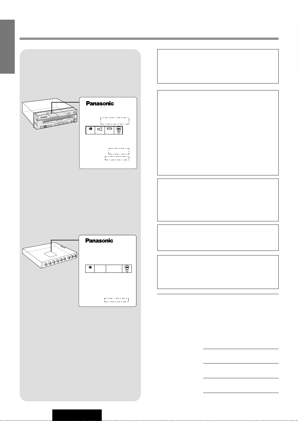
Label Indication and Location
Display Unit
Model No.
N° De Modèle
Manufactured by Matsushita Communication
Industrial Co., Ltd.
Yokohama Japan Made in Japan
YEPOFX4425
(CY-VMC7000U)
(CY-VMD9000U)
1 2 V
Control Unit
Find the model number and serial number on either
the back or bottom of the unit. Please record them in
the space below and retain this booklet as a permanent record of your purchase to help with identification in case of theft.
MODEL NUMBER CY-VMC7000U
SERIAL NUMBER
DATE PURCHASED
FROM
CAUTION:
THIS PRODUCT IS A CLASS I LASER PRODUCT.
USE OF CONTROLS OR ADJUSTMENTS OR
PERFORMANCE OF PROCEDURES OTHER
THAN THOSE SPECIFIED HEREIN MAY RESULT
IN HAZARDOUS RADIATION EXPOSURE.
DO NOT OPEN COVERS AND DO NOT REPAIR
YOURSELF. REFER SERVICING TO QUALIFIED PERSONNEL.
WARNING:
TO REDUCE THE RISK OF FIRE OR ELECTRIC
SHOCK, DO NOT EXPOSE THIS PRODUCT TO
RAIN OR MOISTURE.
TO REDUCE THE RISK OF FIRE OR ELECTRIC
SHOCK, USE ONLY THE INCLUDED COMPONENTS.
CAUTION:
PLEASE FOLLOW THE LAWS AND REGULATIONS OF YOUR STATE, PROVINCE OR
COUNTRY FOR INSTALLATION OF THE UNIT.
Laser products:
Wave length: 780 nm
Laser power: No hazardous radiation is emitted
with safety protection.
E
N
G
L
I
S
H
Model No.
N° De Modèle
1 2 V 5 A
Manufactured by Matsushita Communication
Industrial Co., Ltd.
Yokohama Japan Made in Japan
Serial No.
N° De Série
CY-VMC7000U
8Ω
Page 4
CY-VMC7000U
3
Il est recommandé de noter, dans l’espace prévu cidessous, les numéros de modèle et de série inscrits
soit à l’arrière soit sous le fond de l’appareil, et de
conserver ce manuel comme mémorandum de
l’achat afin de permettre l’identification de l’appareil
en cas de vol.
NUMÉRO DE MODÈLE CY-VMC7000U
NUMÉRO DE SÉRIE
DATE DE L’ACHAT
VENDEUR
Busque el número del modelo y el número de serie
ya sea en la parte trasera o en el fondo de la unidad.
Sírvase anotar dichos números en el espacio siguiente, y mantenga este librete como una anotación
permanente de su compra para ayudar en la identificación en el caso de robo.
NÚMERO DEL MODELO CY-VMC7000U
NÚMERO DE SERIE
FECHA DE COMPRA
NOMBRE DE LA TIENDA
ATTENTION:
CET APPAREIL EST UN PRODUIT LASER DE CLASSE
I.
L’UTILISATION DE COMMANDES OU RÉGLAGES OU
L’EXÉCUTION D’OPÉRATIONS AUTRES QUE CELLES
QUI SONT INDIQUÉES DANS CE DOCUMENT PEUVENT RÉSULTER EN UNE EXPOSITION À UN RAYONNEMENT DANGEREUX.
N’OUVREZ PAS LES COUVERCLES ET N’ESSAYEZ
PAS D’EFFECTUER VOUS-MÊME DES RÉPARATIONS.
ADRESSEZ-VOUS À UN PERSONNEL QUALIFIÉ POUR
TOUTE RÉPARATION.
MISE EN GARDE:
POUR RÉDUIRE LES RISQUES D’INCENDIE OU
D’ÉLECTROCUTION, N’EXPOSEZ PAS CET APPAREIL
À LA PLUIE OU À L’HUMIDITÉ.
AFIN DE PRÉVENIR TOUT RISQUE D’INCENDIE,
UTILISER UNIQUEMENT LES COMPOSANTS FOURNIS.
Produits laser:
Longueur d’onde: 780 nm
Puissance du laser: Aucune radiation dangereuse n’est
émise avec la protection de
sécurité.
ATTENTION :
OBSERVEZ LES LOIS ET REGLEMENTS DE
VOTRE DEPARTEMENT, PROVINCE OU PAYS
POUR L’INSTALLATION DE L’APPAREIL.
PRECAUCIÓN:
RESPETE LAS LEYES Y REGULACIONES DE
SU ESTADO, PROVINCIA O PAÍS PARA LA
INSTALACIÓN DEL APARATO.
PRECAUCIÓN:
ÉSTE ES UN PRODUCTO LÁSER DE LA CLASE I.
LA UTILIZACIÓN DE CONTROLES, EL HACER
AJUSTES O EL SEGUIR PROCEDIMIENTOS DISTINTOS DE LOS ESPECIFICADOS EN ESTE MANUAL
PODRÍA CAUSAR UNA EXPOSICIÍON PELIGROSA A
LA RADIACIÍON.
NO ABRA LAS CUBIERTAS NI HAGA REPARACIONES
USTED MISMO. SOLICITE LOS TRABAJOS DE SERVICIO AL PERSONAL CALIFICADO.
ADVERTENCIA:
PARA REDUCIR EL RIESGO DE INCENDIOS O SACUDIDAS ELÉCTRICAS, NO EXPONGA ESTE PRODUCTO
A LA LLUVIA NI A LA HUMEDAD.
PARA REDUCIR EL RIESGO DE INCENDIOS O SACUDIDAS ELÉCTRICAS, UTILICE SOLAMENTE LOS
COMPONENTES INCLUIDOS.
Productos láser:
Longitud de onda: 780 nm
Potencia láser: Con protección de seguridad no se
emite radiación peligrosa.
Consignes de sécurité
Información para su seguridad
F
R
A
N
Ç
A
I
S
E
S
P
A
Ñ
O
L
Page 5

4
CY-VMC7000U
E
N
G
L
I
S
H
Panasonic welcomes you to our ever growing family of electronic product owners. We know that this product
will bring you many hours of enjoyment. Our reputation is built on precise electronic and mechanical engineering, manufactured with carefully selected components and assembled by people who take pride in their work.
Once you discover the quality, reliability, and value we have built into this product, you too will be proud to be
a member of our family.
❏ Features
■ Integration of the monitor and CD player
■ 7-inch wide LCD display
Delivers images of high quality and superb color reproduction.
■ Fully powered display positioning mechanism (except for lateral angle)
Positioning of the display unit is fully power driven. This includes extending the unit, raising it to upright
position, adjusting its vertical (tilt) angle and moving it to the front and rear.
The lateral angle to the right and left can be adjusted manually.
■ ID code setup
4-digit ID code for increased security.
■ Built-in automatic dimmer
The brightness of the screen is automatically adjusted in response to surrounding brightness.
■ External extension terminal
¡Two video input (on the control unit side)
You can connect a car navigation system, DVD player, VCR, camcorder and rear view camera with this
unit if they have video output type terminal.
¡One video output (on the control unit side)
You can connect another monitor for passengers in the rear seat. (You can enjoy a map of the car navigation on the front monitor, and passengers in the rear seat can enjoy video picture on the rear monitor
at the same time. )
¡One pre-out cord (on the display unit side)
You can connect this unit with 1 DIN audio unit.
You can organize more advanced system by integrating an optional AV control
unit with receiver (CA-TU7000U).
Refer to instructions supplied with devices that are connected to this unit for further information such as operations
and connections if you integrate an AV control unit with receiver.
Note: This book describes a connection with Panasonic Car Navigation System. However, Panasonic Car
Navigation System is not on the market at this moment (Febuary 2000). Therefore, the descriptions with
regard to Panasonic Car Navigation System are marked with light gray belt to distinguish them from others.
Page 6
5
CY-VMC7000U
E
N
G
L
I
S
H
Contents
Safety Information .......................................................................................... Page 2
Features .................................................................................................................. 4
¢¢
Use This Product Safely ............................................................................ 10
¢¢
Components / Remote Control Preparation .......................................... 12
Components, Battery Installation and battery notes
¢¢
Name of Controls and Functions ............................................................. 13
Name of buttons and its functions
¢¢
General .......................................................................................................... 14
Power, mode change, volume, mute, display open/close and monitor position adjustment
¢¢
CD Player ...................................................................................................... 16
Loading/ejecting a disc, CD play, track selection, search, repeat, random and scan
¢¢
Picture / Sound from Auxiliary Devices ................................................. 18
Car navigation system, DVD player, VCR / camcorder, rear view camera and rear seat
monitor.
¢¢
Useful Functions ......................................................................................... 22
Aspect ratio change
¢¢
User Settings ................................................................................................ 24
Monitor position, navigation setup, rear view camera setup, clock setting, ID code setting,
button operation sound and video control setting
¢¢
Display Settings .......................................................................................... 32
Dimmer, contrast, brightness, color and tint
¢¢
Installation Guide ........................................................................................ 34
Step-by-step procedures
¢¢
Electrical Connections ............................................................................... 42
Cautions and cable wiring diagram
¢¢
Troubleshooting .......................................................................................... 48
Where to get service help, troubleshooting tips, error display messages and reset switch
¢¢
Maintenance ................................................................................................. 53
Care of the unit and notes on CD
¢¢
Specifications .............................................................................................. 55
Page 7

10
CY-VMC7000U
1
E
N
G
L
I
S
H
When Driving
Keep the volume level low enough to be aware of road and traffic conditions.
When Car Washing
Do not expose the product, including the speakers and CDs, to water or excessive moisture. This could cause electrical
shorts, fire, or other damage.
When Parked
Parking in direct sunlight can produce very high temperatures inside your vehicle. Give the interior a chance to cool down
before switching the unit on.
Use the Proper Power Supply
This product is designed to operate with a 12 volt, negative ground battery system (the normal system in a North American
car.)
Disc Mechanism
Do not insert coins or any small objects. Keep screwdrivers and other metallic objects away from the disc mechanism and
disc.
Use Authorized Servicenters
Do not attempt to disassemble or adjust this precision product. Please refer to the Servicenter list included with this product for service assistance.
For Installation
The product should be installed in a horizontal position with the front end up at a convenient angle, but not more than 30˚.
WARNING:
TO AVOID RISK OF SERIOUS INJURY OR POSSIBLE VIOLATION OF
LAWS, NOT FOR USE WHERE VISIBLE TO DRIVER FOR ANY PURPOSE
OTHER THAN NAVIGATION OR USE WITH REAR VIEW CAMERA.
When Driving
¡The driver must not operate the color LCD monitor. Operating the color LCD monitor may lead to carelessness and
cause an accident. Stop your vehicle in a safe location when operating the unit.
¡The driver must not watch videos while driving. It may lead to carelessness and cause an accident.
¡Keep the unit at an appropriate sound level. Driving with the sound at a level that prevents you from hearing sounds
outside and around the vehicle may cause an accident.
Use This Product Safely
Page 8
2
E
N
G
L
I
S
H
CY-VMC7000U
ID Code
Prior to operating this unit, it is a advisable to assign your 4-digit ID code for security. (Make sure to use four digits for ID
code. ID code can not be set with two or three digits.)
Once the ID code has been set, the unit cannot be operated if the main power supply is disconnected then re-connected. It
is electronically locked so that a thief could not use the stolen unit unless that person knows the code you have set.
The ID code operation must be performed only by the person whom the unit belongs to.
Generally, it is not necessary to enter the ID code each time when using the unit if it has never been disconnected from the
main power supply (car battery). For the ID code setting procedures, see pages 28 to 29.
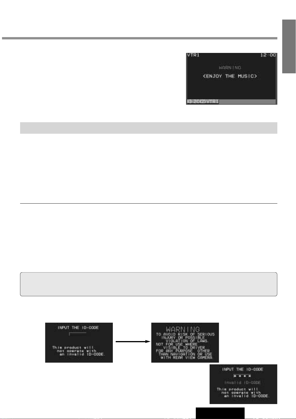
ID Code Input
Enter the ID code after turning on the power and activating the display.
Note: When failing in entering ID code, a screen on the right is displayed, and the
unit beeps three times. Enter a correct ID code.
In case of failing in entering ID code three times consecutively, the power is turned
off. Turn on the power again and enter a correct ID code in this case.
Caution: Record your registered ID code and keep it in a secure location. If you forget it, you will be unable
to use the unit. In case that you can not operate the unit because of forgetting the ID code, please consult your nearest
Panasonic Servicenter.
¡Picture might not be displayed, or it might take more time than usual to display picture in low temperature.
Also, movement of picture might become labored, or picture quality might become deteriorate in low temperature. (practicable temperature: 0 °C - 40 °C)
¡Do not touch the LCD (liquid crystal display).
If you touch the LCD, your fingerprints will be conspicuous because the surface of the LCD was specially
processed.
¡In some cases, noise is generated. It depends on the position or direction of a cellular phone.
Change the position or direction of the cellular phone, or keep it away from the unit.
Cautions
This system is designed so that you can not see picture from VCR, DVD player, and other devices while
you are driving.
¡
Park your car in a safe place and engage the parking brake lever
before watching the monitor.
¡
Picture can be seen on the second monitor.
11
Note:
Be sure to connect the parking brake connection lead. (apage 46)
Success
Page 9
12
CY-VMC7000U
3
E
N
G
L
I
S
H
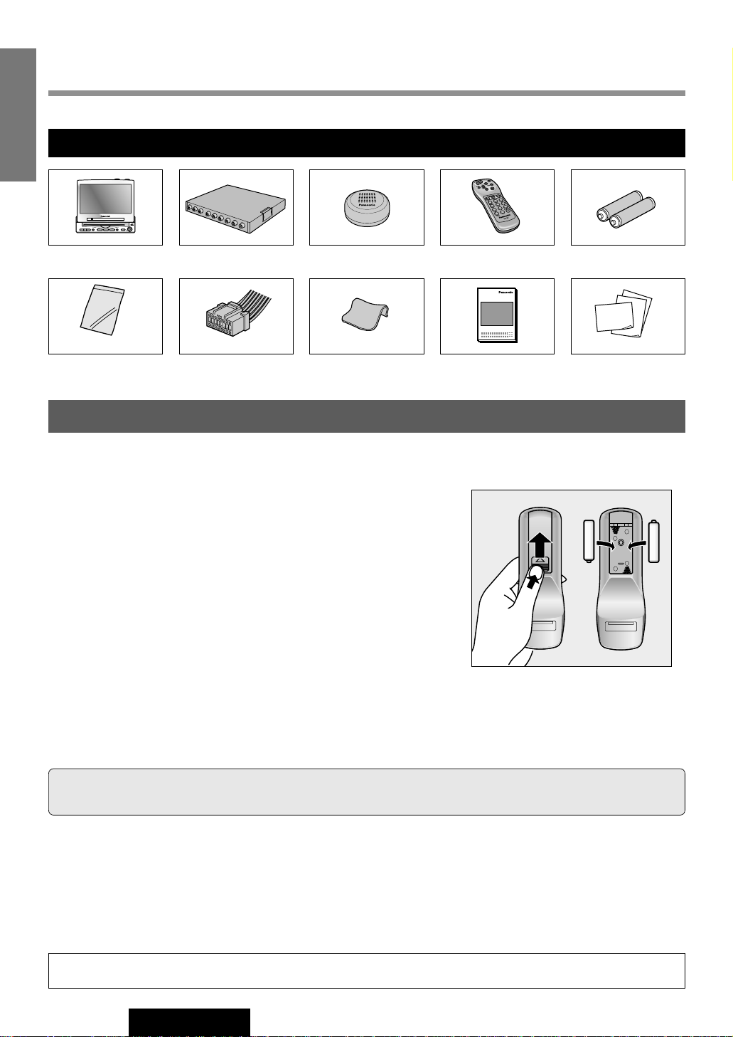
Components / Remote Control Preparation
Battery Insertion
1. Open the battery holder cover.
Lightly depress the cover and slide it out.
2. Insert the battery.
Insert batteries in the correct direction, making sure that their positive (+)
and negative (–) ends match the same symbols in the battery holder.
3. Replace the cover.
The cover is fixed in place with a click.
Battery Notes
¡Battery type: Batteries to be used: Two manganese UM4 AAA dry cells (R03) (do not use alkaline dry cells.)
¡Battery life: About 5 months under normal conditions of use. (Manganese dry cells at normal temperature)
¡Do not disassemble or short the batteries. Do not throw the batteries into a fire.
¡To avoid the risk of an accident, keep the batteries away from children.
¡To store batteries, insulate them with tape or the like. Contact with metallic objects or other batteries can cause ignition or
rupture.
¡If the batteries are used in the wrong way, there is the danger of liquid leakage, rupture, injuries, and failure. (Insert bat-
teries correctly with respect to their positive (+) and negative (–) ends.)
Caution: When decayed, follow the rules and regulations of your country.
(−)
(+)
(+)
(−)
−
+
−
+
Caution: Improper use of batteries may cause overheating, explosion or ignition, resulting in injury or
fire. Battery leakage may cause damage to the unit.
Remote Control Preparation
1. Display Unit
Components
1
2. Control Unit
1
3. Speaker
1
4. Remote Control
1
5. Batteries
2
6. Installation
Hardware
1 set (a page 34)
7. Power Connector
1
8. Wiping Cloth
1
9. Operating
Instructions
1
10. Warranty Card, etc.
3
2
1
6
5
4
9
8
7
0
CY-VMC7000U
IN-DASH 7 WIDE COLOR LCD MONITOR / PLAYER
VOLUME
NAVIGATION ASPECT
MENUMUTE MODE NAVI
DISC/BAND
TRACK/
ENTER
YUNE
ASP
P·MODEPOWER
A
XXXXXXXXXXXXXXX
XXXXXXXXXXXXXXXXX
XXXXXXXXXXXXXX
XXXXXXXXXXXXXXXX
OO-OOOOO
Page 10
13
CY-VMC7000U
4
E
N
G
L
I
S
H
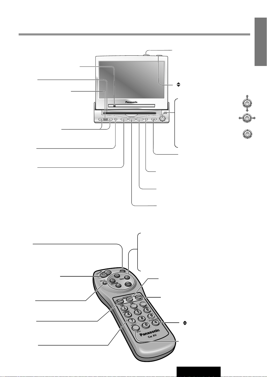
Name of Controls and Functions
1
2
3
4
5
6
7
8
9
A
0
Aim the remote control at the remote control sensor of the display unit and operate it.
Remote Control
[PWR]
¡Switches on/off the power. (a page 14)
[}] [{] (DISC/BAND)
¡Selects (vertically) or adjusts an operation or item.
[]] [[] (TRACK)
¡Selects or searches a track. (a page 16)
¡Selects (horizontally) or adjusts an operation or item.
[ENTER]
¡Determines an operation or item.
[MODE]
¡Switches on/off the power. (a page 14)
¡Changes the modes such as sound and pic-
ture. (a page 14)
[0] to [9]
¡Selects listening pattern. (a page 17)
¡Sets the ID code. (a page 28)
[MENU]
¡Shows the menu screen. (a page 24)
¡Shows the rear monitor setting menu.
(a page 20)
[]
(OPEN/CLOSE)
¡Opens/closes the monitor.
(a page 14)
[}] [{] (VOLUME)
¡Adjusts the sound volume.
(a page 14)
[MUTE]
¡Mutes the sound temporarily.
(a page 14)
[NA VI](NAVIGATION)
¡Activates/inactivates the navigation.
(a page 18)
[A] (ASPECT)
¡Selects the aspect ratio.
(a page 22)
Display Unit
VOLUME
MENUMUTE MODE NAVI
NAVIGATION ASPECT
P·MODEPOWER
ASP
ENTER
CY-VMC7000U
IN-DASH 7 WIDE COLOR LCD MONITOR / CD PLAYER
DISC/BAND
TRACK/
YUNE
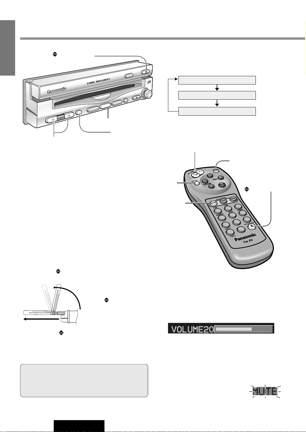
Dimmer sensor (a page 32)
Remote control sensor
[MENU]
¡Shows the menu screen. (a page 24)
¡Shows the rear monitor setting menu.
(a page 20)
[}] [{] (VOLUME)
¡Adjusts the sound volume. (a page 14)
[MUTE]
¡Mutes the sound temporarily. (a page 14)
[TIL T]
¡Shows the monitor position setting
menu. (a page 15)
¡Tilts the monitor forward temporarily.
(a page 15)
[ASP] (ASPECT)
¡Selects the aspect ratio. (a page 22)
[]
(OPEN/CLOSE)
¡Opens/closes the monitor. (a page 14)
[NA VI](NAVIGATION)
¡Activates/inactivates the navigation. (a page 18)
[MODE] (POWER)
¡Switches on/off the power. (a page 14)
¡Changes the modes such as sound and picture.
(a page 14)
[u]
¡Ejects a CD. (a page 16)
CD slot
[}] [{] (DISC/BAND)
¡Selects (vertically) or adjusts
an operation or item.
[]] [[] (TRACK/TUNE)
¡Selects or searches a track.
(a page 16)
¡Selects (horizontally) or
adjusts an operation or item.
[ENTER]
¡Determines an operation or item.
ENTER
ENTER
ENTER
Page 11
If the unit stops halfway,
press
[]
(OPEN/CLOSE)
again and draw it all the
way in.
Display Open / Close
OPEN
: Press
[]
(OPEN/CLOSE).
PO
WER
P·MODE
TRACK/
TUNE
VOLUME
MENU
MUTE
MODE
NAVI
NAVIGATION
ASPECT
OPEN/CLOSE
ASP
ENTER
TILT
INDASH 7 WIDE COLOR LCD MONITOR / CD PLAYER
CY-TU7000U
DISC/BAND
MODE
MUTE
14
CY-VMC7000U
5
E
N
G
L
I
S
H
General
[]
(OPEN/CLOSE)
[MUTE]
[{][}] (VOLUME)
[MODE] (POWER)
Power
ON : Press [MODE] (POWER). (On the display unit)
Press [PWR] or [MODE]. (On the remote control)
Mode
Press [MODE] to change the mode.
Volume
[}] (VOLUME) : Up
[{] (VOLUME) : Down
MUTE
MUTE ON : Press [MUTE].
MUTE OFF : Press [MUTE] again.
Note: The sound level for each source is stored in
memory.
OFF : Press [MODE] (POWER) again for more than 2
seconds. (On the display unit)
Press [PWR] again or [MODE] again for more
than 2 seconds. (On the remote control)
Default : Volume 24 Setting Range : 0 to 40
VTR1
VTR2
CD Player
Turn the key in the ignition until the accessory indicator
lights.
CLOSE
: Press
[]
(OPEN/CLOSE) again.
(After return the lateral angle to the neutral position.)
Warning: Do not insert hands, fingers or foreign
objects into the unit while the display is moving.
Inserting your hands, fingers or foreign objects into
the unit can cause injuries and damage to the unit.
(a page 18)
(a page 18)
(a page 16)
[]
(OPEN/CLOSE)
[MODE]
[MUTE]
[PWR] (Power)
[}][{] (VOLUME)
Note: When the display unit is opened or closed, a loud beep
sounds three times.
1
3
2
6
5
4
8
7
0
A
9
Page 12
15
CY-VMC7000U
6
E
N
G
L
I
S
H
Caution: Do not place any object on the display unit, or subject it to undue force.
Cautions:
¡For smooth adjustment, make sure to first return the lateral angle to the neutral position and then adjust the tilt angle.
¡Do not manually change the position of the unit by using force.
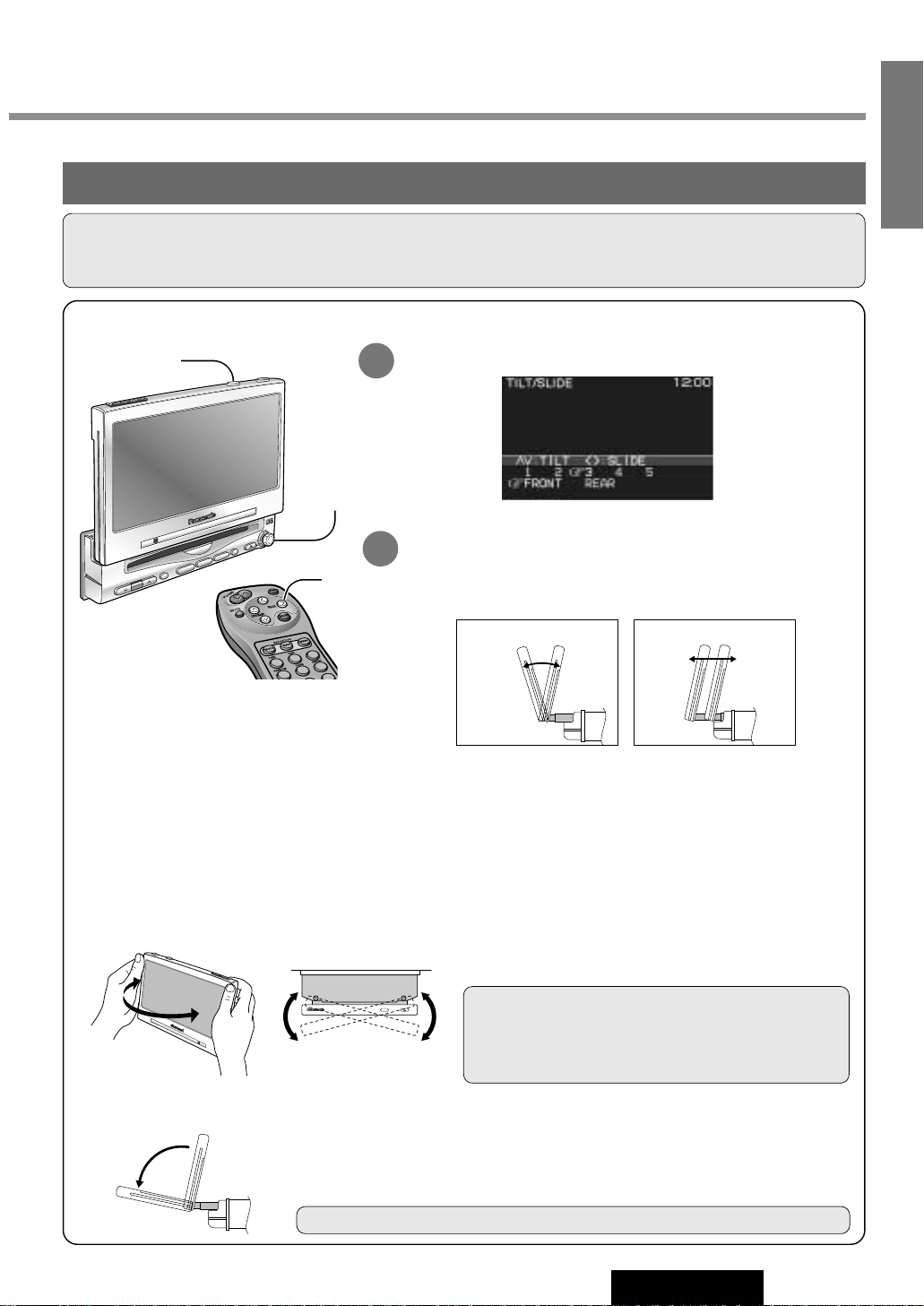
Monitor Position Adjustment
Tilt Angle / Front-Rear Position
POWER
VOLUME
MENU
MUTE
MODE
NAVI
N
A
V
IG
A
T
IO
N
ASP
E
N
T
E
R
T
I
L
T
ASPECT
C
Y
-V
M
C
7
0
0
0
U
IN-DASH 7 WIDE COLOR LCD MONITOR / PLAYER
DISC/BAND
Position "REAR" and tilt angle "5"
cannot be selected at the same time.
Press and hold [TIL T]on the display unit for more than 1 second.
Monitor Position Setting Menu
Press [}] or [{] to adjust the tilt angle. Press []] or [[] to
move the display to the front or rear position.
Notes:
¡Press [MODE] to return to the regular mode.
¡The monitor position setting menu is automatically closed if no operation is performed for about 60 seconds.
¡Vertical angle (TILT) and front-rear position data are saved in the memory, so when the display unit is drawn out
next, it is automatically set at the angle and in the position adjusted before.
¡After adjusting its angle, also adjust the brightness to make it easy for you to watch. (a page 32)
¡The display position can also be set on the main menu screen. (a page 24)
Display Unit Lateral Angle Adjustment
Folding Down the Display Temporarily
Hold the display unit by the non-slip part in the
upper half of it, and adjust its lateral angle.
Caution: There is the danger of your fingers being
pinched if you hold the unit by lower part. Hold the unit
by the upper half of it, and move it carefully without
applying undue force.
Fold Down : Press [TILT] on the display unit.
Raise : Press [TILT] again on the display unit.
Note: Even when the unit is power off, you can fold down the display temporarily.
2
1
TILT
Tilt Angle
1 to 5
[{][}]
Front-Rear Position
Front Rear
[]][[]
[TILT]
[}][{]
[]][[] (Adjust)
1
2
3
4
5
6
[}][{]
[]][[] (Adjust)
Page 13
VOLUME
MENUMUTE MODE NAVI
NAVIGATION ASPECT
P·MODEPOWER
ASP
ENTER
CY-VMC7000U
IN-DASH 7 WIDE COLOR LCD MONITOR / CD PLAYER
DISC/BAND
TRACK/
YUNE
MODE
ENTER
P
O
W
E
R
P
·M
O
D
E
TRACK/
YUNE
V
O
L
U
M
E
M
E
N
U
M
U
TE
M
O
D
E
N
A
V
I
N
A
V
IG
A
T
IO
N
A
S
P
E
C
T
AS
P
E
N
TE
R
C
Y
-V
M
C
7000U
IN-DASH 7 WIDE COLOR LCD MONITOR / PLAYER
D
ISC/BA
ND
16
CY-VMC7000U
7
E
N
G
L
I
S
H
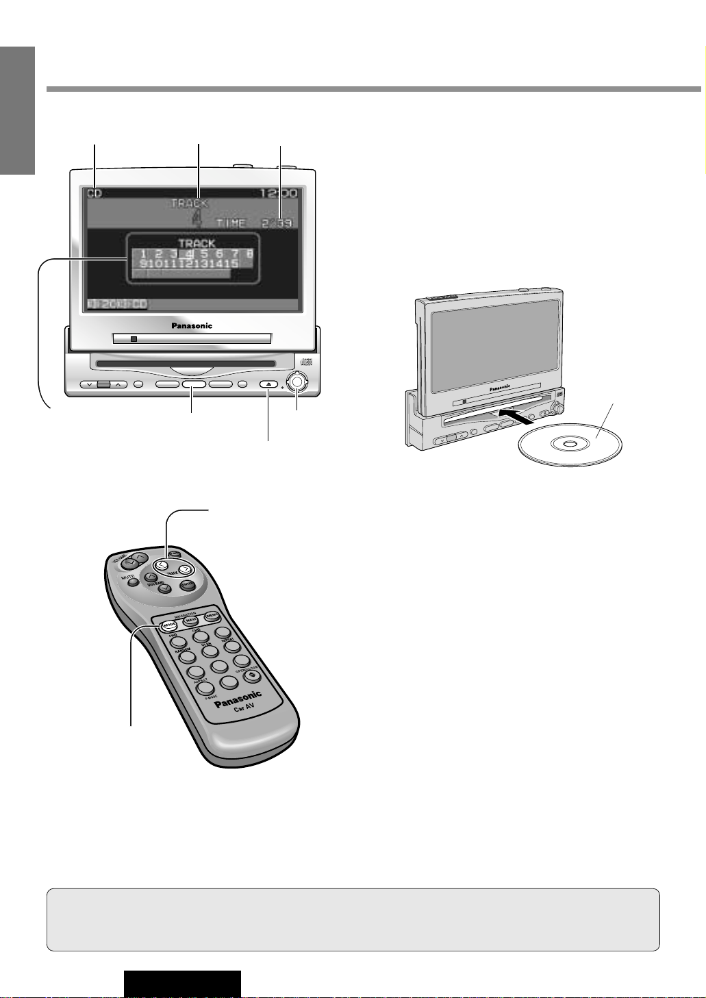
Disc Insert
Playback starts automatically.
Notes :
¡Load a CD after making sure that there is no CD
in the disc compartment. (If "NO DISC" is displayed while the CD mode is activated, you will
find there is no CD in the compartment.)
¡Loading a CD when the power is off will turn
the power on.
Track Selection
[[] (TRACK) : Next track
[]] (TRACK) : Beginning of the current track
Previous track (Press twice.)
Track Search
Press and hold.
[[] (TRACK) : Fast forward
[]] (TRACK) : Fast backward
CD Player
Label Side
Disc Eject
Press [u] to stop playback and eject the CD.
Cautions:
¡Do not use irregularly shaped CDs.
¡Do not insert foreign matter into the disc slots.
[MODE]
[]][[] (TRACK)
Notes :
¡You can play a CD even if the monitor is closed.
¡If you leave a CD at the CD slot for approximately 30 seconds, the CD is loaded into the compartment automatically
after loud beep is energized three times.
Track Number
Play Time
Mode Display
Number of Track
The monitor shows
“Over B” when the
number of tracks is
21 or more.
[u] (Eject)
When CD is in the player
Press [MODE] to change to CD player mode and
playback starts.
1
2
3
4
5
6
7
8
9
A
0
[]][[] (TRACK)
[MODE]
Page 14

17
CY-VMC7000U
8
E
N
G
L
I
S
H
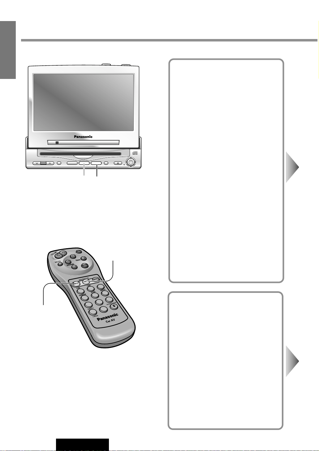
Various Way of Listening
(Only on the remote control)
Repeat Play
Repeat the current selection.
Press [6] (REPEAT) again to cancel.
Random Play
All the available tracks are
played in a random sequence.
Press [4] (RANDOM) again to cancel.
Scan Play
The first 10 seconds of each
track plays in sequence.
Press [5] (SCAN) again to cancel.
With the scanning of all tracks
over, the original program starts
playing from the beginning.
Press [4] (RANDOM)
Press [5] (SCAN)
Press [6] (REPEAT)
1
2
3
4
5
6
7
8
9
0
4
1
2
3
4
5
6
7
8
9
0
5
1
2
3
4
5
6
7
8
9
0
6
Page 15
18
CY-VMC7000U
9
E
N
G
L
I
S
H
Picture/Sound from Auxiliary Devices
Car Navigation
Preparation:
¡Connect a car navigation system.
¡Select a terminal in the "NAVI SETUP"
screen according to the terminal actually
connected to the car navigation system.
(a page 24)
DVD Player
Preparation: Connect a DVD player.
(a page 44)
VOLUME
MENUMUTE MODE NAVI
NAVIGATION ASPECT
P·MODEPOWER
ASP
ENTER
CY-VMC7000U
IN-DASH 7 WIDE COLOR LCD MONITOR / CD PLAYER
DISC/BAND
TRACK/
YUNE
MODE NAVI
[MODE]
[NAVI] (NAVIGATION)
1
2
3
4
5
6
7
8
9
A
0
[MODE]
[NAVI] (NAVIGATION)
Page 16
19
CY-VMC7000U
10
E
N
G
L
I
S
H
When you connect a car navigation system through
RGB cord [Panasonic Car Navigation (not available
yet)]:
Car Navigation ON : Press [NAVI] (NAVIGATION).
Car Navigation OFF : Press [NAVI] (NAVIGATION) again.
When you connect a car navigation system to VTR1IN or VTR2-IN terminal (other brand’s car navigation
system):
Car Navigation ON : Press [NAVI] (NAVIGATION).
Car Navigation OFF : Press [NAVI] (NAVIGATION) again.
Or press [MODE] to change to the VTR1 or VTR2 mode.
Select the same mode (VTR1 or VTR2) as the terminal that connected to a car navigation system (VTR1-IN or VTR2-IN).
DVD video/audio
output
RGB: car navigation
RGB input cord
VTR1-IN
VTR2-IN
Panasonic Car
Navigation System
CY-VMC7000U
Control Unit
CY-VMC7000U
Display Unit
(Example)
Other brand’s car
navigation system
CY-VMC7000U
Control Unit
VTR1-IN
VTR2-IN
(Example)
Press [MODE] to change to the VTR1 or VTR2 mode.
Select the same mode (VTR1 or VTR2) as the terminal that is
connected to a DVD video player (VTR1-IN or VTR2-IN).
Note: This unit is not equipped with a power amplifier. If you
connect a DVD player / receiver equipped with a power amplifier (such as CQ-DVR909U) to this unit, you can enjoy powerful
sound.
CY-VMC7000U
Control Unit
VTR1-IN
VTR2-IN
Panasonic DVD
Player/Receiver
(CQ-DVR909U)
VTR-OUT
FRONT
(Example)
Note: When you connect a Panasonic car navigation system with a
built-in DVD player, use an RCA cord as well.
Page 17

11
E
N
G
L
I
S
H
CY-VMC7000U
Picture/Sound from Auxiliary Devices
(continued)
Rear Seat Monitor
You can have different picture or sound at the
front monitor and rear monitor at the same
time.
Default : AUTO
Preparation: Connect another monitor.
(a page 44)
20
VCR / Camcorder
Preparation: Connect a VCR or Camcorder.
(a page 46)
Rear View Camera
Preparation:
¡Connect a rear view camera and a reverse
lead. (a page 47)
¡Select a terminal in the "CAMERA IN" screen
according to the terminal actually connected
to the rear view camera. (a page 26)
1
2
3
4
5
6
7
8
9
A
0
VOLUME
MENUMUTE MODE NAVI
NAVIGATION ASPECT
P·MODEPOWER
ASP
ENTER
CY-VMC7000U
IN-DASH 7 WIDE COLOR LCD MONITOR / CD PLAYER
DISC/BAND
TRACK/
YUNE
MENU MODE
ENTER
[MODE]
[]][[] (Select)
[MODE]
[ENTER]
[MENU]
[MENU]
[]] [[] (Select)
[ENTER]
Page 18

21
CY-VMC7000U
12
E
N
G
L
I
S
H
Notes:
¡Press [MENU] or [MODE] to return to the regular mode.
¡The display returns to the previous one if there is no operation for 60 seconds, after changing to the rear monitor
setting menu.
¡Picture and sound from the car navigation system connected to an RGB are not available at the rear monitor.
¡Sound in the CD mode is not available at the rear monitor.
2
1
Press and hold [MENU] for more than 2 seconds.
Press [[] or []] to select an item.
Press [ENTER] to set.
3
: Picture and sound come out. These are in the
same mode as the front seat monitor.
: Picture and sound in the VTR1 mode always
come out.
: Picture and sound in the VTR2 mode always
come out.
VTR2
VTR1
AUTO
Rear Monitor Setting Menu
Shift the transmission gear into the reverse position.
The display shows a picture from the rear view camera.
Notes:
¡You can see a picture from the rear view camera even if the power of the
display unit is inactivated.
¡You can a see picture from the rear view camera if you change the mode
to the same one (VTR1 or VTR2) as the terminal to which the rear view
camera was connected (VTR1-IN or VTR2-IN).
Press [MODE] to change to the VTR1 or VTR2 mode.
Select the same mode (VTR1 or VTR2) as the terminal that is
connected to a VCR or Camcorder (VTR1-IN or VTR2-IN).
Rear View Camera
CY-VMC7000U
Control Unit
VTR1-IN
VTR2-IN
(Example)
CY-VMC7000U
Control Unit
VTR1-IN VTR2-IN
Camcorder
VCR
(Example)
INTELLIGENT SYSTEM
BS G-CODE
POWER
Rear Seat
Monitor
CY-VMC7000U
Control Unit
VIDEO-OUT
(Example)
Page 19

22
CY-VMC7000U
13
E
N
G
L
I
S
H
Useful Functions
Aspect Ratio
(for VTR Mode)
Default : Normal
Mode: 4 types
1
2
3
4
5
6
7
8
9
A
0
A
VOLUME
MENUMUTE MODE NAVI
NAVIGATION ASPECT
P·MODEPOWER
ASP
ENTER
CY-VMC7000U
IN-DASH 7 WIDE COLOR LCD MONITOR / CD PLAYER
DISC/BAND
TRACK/
YUNE
ASP
[ASP] (ASPECT)
[A] (ASPECT)
Page 20

23
CY-VMC7000U
14
E
N
G
L
I
S
H
Notes:
¡This adjustment is common to VTR1 and VTR2.
¡You can not change the aspect in the menu screen and a screen in the CD mode. These are fixed to “Full”.
¡The “Zoom” and “Just” screens do not apply to car navigation images.
¡When the rear view camera is in operation with the transmission gear shift in the reverse position, the image is
shown on the “Full” screen only.
¡In some cases, the picture looks different from the original one due to your selection of aspect.
Press [ASP] (ASPECT) on the display unit or press [A] (ASPECT) on the remote control to change the aspect
ratio as follows.
Normal
¡The conventional display image has a 4 to 3 ratio of horizontal to
vertical.
¡In this case, a blank area remains on the right and left sides of the
display.
Full
¡The screen is extended horizontally as a whole to the aspect ratio
of 16 to 9.
¡The extension ratio is the same at any point of the screen.
Zoom
¡The screen is fully extended at the normal aspect ratio of 4 to 3.
¡The top and bottom of the screen are slightly cut.
Just
¡The screen is extended horizontally to the aspect ratio of 16 to 9.
¡The extension ratio increases toward the right and left ends of the
screen.
Cautions:
¡This is to remind you that compression or extension of the screen using the aspect ratio (screen mode) chang-
ing function of this product for commercial purpose of profit making or viewing / listening by the public could
infringe on the rights of the author protected by the copyright law.
¡If you expand normal picture (4 to 3) by using “Just”, “Zoom” or “Full” aspect to the full of the screen, you
might not see the periphery of the picture, or you might see deformed picture. Therefore, use the “Normal”
mode when you see original picture in deference to picture-making purpose.
Page 21

VOLUME
MENUMUTE MODE NAVI
NAVIGATION ASPECT
P·MODEPOWER
ASP
ENTER
CY-VMC7000U
IN-DASH 7 WIDE COLOR LCD MONITOR / CD PLAYER
DISC/BAND
TRACK/
YUNE
ENTER
VOLUME
MENUMUTE MODE NAVI
NAVIGATION ASPECT
P·MODEPOWER
ASP
ENTER
CY-VMC7000U
IN-DASH 7 WIDE COLOR LCD MONITOR / CD PLAYER
DISC/BAND
TRACK/
YUNE
MENU MODE
24
CY-VMC7000U
15
E
N
G
L
I
S
H
User Settings
Monitor Position
Default : TILT...3
SLIDE...Front
Setting range : TILT...1 to 5
SLIDE...Front, Rear
Navigation Set Up
Default : Navigation input...RGB
Speaker setting...AUTO
Note: You can set the Navigation speaker
setting when "RGB" is selected on Navigation
input.
USER
TILT / SLIDE
NAVI SETUP
1 2
Press [MENU] to display the main menu.
q
Press [[] or []] to select "USER".
Press
[}] or [{] to select an item.
w Press [ENTER] to set.
Select
Select
Select
[}] [{]
[]] [[]
(Select)
[ENTER]
[MODE] [MENU]
Page 22

25
CY-VMC7000U
16
E
N
G
L
I
S
H
Notes:
¡Press [MODE] to return to the regular mode.
¡The display returns to the previous one if there is no
operation for more than 60 seconds after changing
to the setting / adjusting menu.
3
q Press [[], []], [}] or [{] to select and
adjust.
w Press [ENTER] to set. (for NAVI SETUP)
The monitor position setting menu can also be displayed by pressing the [TILT]button on the display unit
for more than 1 second. (For details, refer to page 15.)
Notes:
¡For smooth adjustment, make sure to first return the lateral angle to the neutral position and then adjust the tilt
angle.
¡Front-rear position "REAR" and tilt angle "5" cannot be selected at the same time.
Tilting angle adjustment :
Front-rear position :
REARFRONT
54321
Navigation Input
: Connected to the RGB input cord, or a car navigation system not connected
: Connected to the VTR1-IN
: Connected to the VTR2-IN
VTR2
VTR1
RGB
NAVI IN
Speaker Setting (Output setting of accessory speakers)
: Sound does not come out.
: The sound comes out in the same mode as the picture.
: The sound from the Panasonic car navigation system (not available yet) always comes out.
NAVI
AUTO
OFF
SP SETUP
[}] [{]
[]] [[]
(Select and Adjust)
[ENTER]
1
2
3
4
5
6
7
8
9
A
0
[}] [{]
[]] [[]
(Select and Adjust)
[ENTER]
[MODE]
[MENU]
Tilt Angle
1 to 5
[{][}]
Front-Rear Position
Front Rear
[]][[]
DISC/BAND
TRACK/
ENTER
ENTER
YUNE
VOLUME
IN-DASH 7 WIDE COLOR LCD MONITOR / CD PLAYER
MENUMUTE MODE NAVI
CY-VMC7000U
NAVIGATION ASPECT
ASP
P·MODEPOWER
Page 23

VOLUME
MENUMUTE MODE NAVI
NAVIGATION ASPECT
P·MODEPOWER
ASP
ENTER
CY-VMC7000U
IN-DASH 7 WIDE COLOR LCD MONITOR / CD PLAYER
DISC/BAND
TRACK/
YUNE
ENTER
VOLUME
MENUMUTE MODE NAVI
NAVIGATION ASPECT
P·MODEPOWER
ASP
ENTER
CY-VMC7000U
IN-DASH 7 WIDE COLOR LCD MONITOR / CD PLAYER
DISC/BAND
TRACK/
YUNE
MENU MODE
26
CY-VMC7000U
17
E
N
G
L
I
S
H
User Settings (continued)
Clock Setting
Default : Clock display...OFF
USER
CLOCK
Rear View Camera
Set Up
Default : OFF
CAMERA IN
Select
Select
Select
1 2
Press [MENU] to display the main menu.
q
Press [[] or []] to select "USER".
Press
[}] or [{] to select an item.
w Press [ENTER] to set.
[}] [{]
[]] [[]
(Select)
[ENTER]
[MODE] [MENU]
Page 24

VOLUME
MENUMUTE MODE NAVI
NAVIGATION ASPECT
P·MODEPOWER
ASP
ENTER
CY-VMC7000U
IN-DASH 7 WIDE COLOR LCD MONITOR / CD PLAYER
DISC/BAND
TRACK/
YUNE
ENTER
27
CY-VMC7000U
18
E
N
G
L
I
S
H
Clock Display
: Clock display OFF
: Clock display ON ([12:00] is displayed before adjusting
the clock.)
ON
OFF
DISPLAY
Clock Adjustment
Adjust the time (12-hour system).
Press []] to adjust the hour.
Press [[] to adjust the minute.
Hold []] or [[] to change numbers rapidly.
ADJUST
Clock Re-adjustment
Reset the clock to zero seconds.
The clock display blinks once and clock starts.
SEC RESET
: Unconnected
: Connected to the VTR1-IN
: Connected to the VTR2-IN
VTR2
VTR1
OFF
Notes:
¡Press [MODE] to return to the regular mode.
¡The display returns to the previous one if there is no
operation for more than 60 seconds after changing
to the setting / adjusting menu.
3
q Press [[], []], [}] or [{] to select
and adjust.
w Press [ENTER] to set.
[}] [{]
[]] [[]
(Select and Adjust)
[ENTER]
1
2
3
4
5
6
7
8
9
A
0
[}] [{]
[]] [[]
(Select and Adjust)
[ENTER]
[MODE]
[MENU]
Notes:
¡Make sure to select “OFF” when no rear view cam-
era is connected.
¡In case using an optional rear view camera, the
reverse lead must be connected. (a page 47)
Clock Display
blinks once
[[] minute
advance
[]] hour
advance
Page 25

VOLUME
MENUMUTE MODE NAVI
NAVIGATION ASPECT
P·MODEPOWER
ASP
ENTER
CY-VMC7000U
IN-DASH 7 WIDE COLOR LCD MONITOR / CD PLAYER
DISC/BAND
TRACK/
YUNE
ENTER
VOLUME
MENUMUTE MODE NAVI
NAVIGATION ASPECT
P·MODEPOWER
ASP
ENTER
CY-VMC7000U
IN-DASH 7 WIDE COLOR LCD MONITOR / CD PLAYER
DISC/BAND
TRACK/
YUNE
MENU MODE
28
CY-VMC7000U
19
E
N
G
L
I
S
H
User Settings (continued)
ID Code setting
Prior to operating this unit, it is advisable to
assign your 4-digit ID code for security.
(Make sure to use four digits for ID code. ID
code can not be set with two or three digits.)
Once the ID code has been set, the unit cannot be operated if the main power supply is
disconnected then re-connected. It is electronically locked so that a thief could not use
the stolen unit unless that person knows the
code you have set.
The ID code operation must be performed
only by the person whom the unit belongs to.
Generally, it is not necessary to enter the ID
code each time when using the unit if it has
never been disconnected from the main
power supply (car battery).
USER
ID-CODE
Caution: Record your registered ID code
and keep it in a secure location. If you forget
it, you will be unable to use the unit. In case
that you can not operate the unit because of
forgetting the ID code, please consult your
nearest Panasonic Servicenter.
Select
Select
1 2
Press [MENU] to display the main menu.
q
Press [[] or []] to select "USER".
Press
[}] or [{] to select an item.
w Press [ENTER] to set.
[}] [{]
[]] [[]
(Select)
[ENTER]
[MODE] [MENU]
Note: Refer to ID Code Input regarding how to
enter the ID code. (a page 11)
Page 26

VOLUME
MENUMUTE MODE NAVI
NAVIGATION ASPECT
P·MODEPOWER
ASP
ENTER
CY-VMC7000U
IN-DASH 7 WIDE COLOR LCD MONITOR / CD PLAYER
DISC/BAND
TRACK/
YUNE
ENTER
29
CY-VMC7000U
20
E
N
G
L
I
S
H
How to Set Your ID Code (For the First Time)
q
Enter an ID code of 4 digits using the buttons [0] to
[9] on the remote control.
Note: When you are setting your ID code for the
first time, it is not necessary to enter the old ID code.
w
Enter the ID code of 4 digits again using the buttons
[0] to [9] on the remote control.
How to Change Your ID Code
q
Enter the preset (old) ID code of 4 digits using the
buttons
[0] to [9] on the remote control. If the
wrong ID code is entered, a new ID code cannot be
registered.
w Enter a new ID code of 4 digits using the buttons [0]
to [9] on the remote control.
e Enter the new ID code of 4 digits again using the
buttons
[0] to [9] on the remote control.
How to Cancel the Known ID Code
q
Enter the preset (old) ID code of 4 digits using the
buttons
[0] to [9] on the remote control. If the
wrong ID code is entered, it is not possible to cancel
the ID code function.
w Press and hold [ENTER] until display the
"Complete!".
The ID code cancelling procedure is completed. The unit now works without an ID code.
Note: Press [MODE] to return to the regular mode.
3
[ENTER]
1
2
3
4
5
6
7
8
9
A
0
1
2
3
4
5
6
7
8
9
0
[}] [{]
[]] [[]
(Select)
[ENTER]
[MODE]
[MENU]
[0]
to [9]
(ID code input)
Enter an ID code by using the remote control.
Note: Should your unit ever require service, cancel your
ID code before sending for repair.
Page 27

30
CY-VMC7000U
21
E
N
G
L
I
S
H
User Settings (continued)
Button Operation Sound
Default : ON
etc.
Video Control Setting
This “Video Control Setting” is required when
you connect a Panasonic car navigation system with a built-in DVD player. (not available
yet)
Default : VTR1
USER
Select
Select
1 2
Press [MENU] to display the main menu.
q
Press [[] or []] to select "USER".
Press
[}] or [{] to select an item.
w Press [ENTER] to set.
[}] [{]
[]] [[]
(Select)
[ENTER]
[MODE] [MENU]
CY-VMC7000U
NAVIGATION ASPECT
ASP
P·MODEPOWER
VOLUME
IN-DASH 7 WIDE COLOR LCD MONITOR / CD PLAYER
MENUMUTE MODE NAVI
MENU MODE
ENTER
ENTER
DISC/BAND
TRACK/
YUNE
DISC/BAND
TRACK/
ENTER
YUNE
VOLUME
IN-DASH 7 WIDE COLOR LCD MONITOR / CD PLAYER
MENUMUTE MODE NAVI
CY-VMC7000U
NAVIGATION ASPECT
ASP
P·MODEPOWER
Page 28

31
CY-VMC7000U
22
E
N
G
L
I
S
H
Beep Setting
: Operation sound (Beep) OFF
: Operation sound (Beep) ON
ON
OFF
BEEP
Video Control Setting
: Connected to the VTR1-IN
: Connected to the VTR2-IN
VTR2
VTR1
VIDEO-CONT
Note: Select a terminal connected to the DVD output terminal of a Panasonic car navigation system with a
built-in DVD player (not available yet) through an RCA cord.
Notes:
¡Press [MODE] to return to the regular mode.
¡The display returns to the previous one if there is no
operation for more than 60 seconds after changing
to the setting / adjusting menu.
3
q Press [[], []], [}] or [{] to select.
w Press [ENTER] to set.
[}] [{]
[]] [[]
(Select)
[ENTER]
1
2
3
4
5
6
7
8
9
A
0
[}] [{]
[]] [[]
(Select)
[ENTER]
[MODE]
[MENU]
Note: The loud beep is energized when
opening or closing the display unit even if
you select OFF for the beep setting.
CY-VMC7000U
NAVIGATION ASPECT
DISC/BAND
TRACK/
ENTER
ENTER
ASP
P·MODEPOWER
YUNE
VOLUME
IN-DASH 7 WIDE COLOR LCD MONITOR / CD PLAYER
MENUMUTE MODE NAVI
Page 29

VOLUME
MENUMUTE MODE NAVI
NAVIGATION ASPECT
P·MODEPOWER
ASP
ENTER
CY-VMC7000U
IN-DASH 7 WIDE COLOR LCD MONITOR / CD PLAYER
DISC/BAND
TRACK/
YUNE
ENTER
VOLUME
MENUMUTE MODE NAVI
NAVIGATION ASPECT
P·MODEPOWER
ASP
ENTER
CY-VMC7000U
IN-DASH 7 WIDE COLOR LCD MONITOR / CD PLAYER
DISC/BAND
TRACK/
YUNE
MENU MODE
32
CY-VMC7000U
23
E
N
G
L
I
S
H
Display Settings
SCREEN
DIMMER
Dimmer
Default : AUTO
CONTRAST
Contrast
Default : ± 0
Setting range : - 15 to + 15
BRIGHT
Brightness
Default : ± 0
Setting range : - 15 to + 15
COLOR
Color
Default : ± 0
Setting range : - 15 to + 15
TINT
Tint
Default : ± 0
Setting range : - 15 to + 15
Select
Select
Select
Select
Select
Select
1 2
Press [MENU] to display the main menu.
q
Press [[] or []] to select "SCREEN".
Press
[}] or [{] to select an item.
w Press [ENTER] to set.
[}] [{]
[]] [[]
(Select)
[ENTER]
[MODE] [MENU]
Page 30

VOLUME
MENUMUTE MODE NAVI
NAVIGATION ASPECT
P·MODEPOWER
ASP
ENTER
CY-VMC7000U
IN-DASH 7 WIDE COLOR LCD MONITOR / CD PLAYER
DISC/BAND
TRACK/
YUNE
ENTER
33
CY-VMC7000U
24
E
N
G
L
I
S
H
: Automatically adjusted according to ambient light intensity.
: Darker (1) to Brighter (4)
Press [ENTER] to set.
4321
AUTO
Increase the contrast
between black and white.
Decrease the contrast
between black and white.
Darken
Lighten
Deepen the depth of
color on the display
Lighten the depth of
color on the display
Emphasize green in
the color image
Emphasize red in
the color image
Notes:
¡Press [MODE] to return to the regular mode.
¡The display returns to the previous one if there is no
operation for more than 60 seconds after changing
to the setting / adjusting menu.
3
Press [[] or []] to select and adjust.
[]] [[]
(Select and Adjust)
[ENTER]
1
2
3
4
5
6
7
8
9
A
0
[}] [{]
[]] [[]
(Select and Adjust)
[ENTER]
[MODE]
[MENU]
Page 31

QtyDiagramItemNo.
34
CY-VMC7000U
25
E
N
G
L
I
S
H
Installation Guide
W ARNING
This installation information is designed for experienced installers
and is not intended for non-technical individuals. It does not contain
warnings or cautions of potential dangers involved in attempting to
install this product.
Any attempt to install this product in a motor car by anyone other
than qualified installer could cause damage to the electrical system
and could result in serious personal injury or death.
❏ Overview
This product should be installed by a professional.
However, if you plan to install this product yourself,
your first step is to decide where to install it. The
instructions in these pages will guide you through
the remaining steps: (Please refer to the “WARN-
ING” statement above).
¡Identify and label the car wires.
¡Connect the car wires to the wires of the power
connector.
¡Install the unit in the dashboard.
¡Check the operation of the unit.
If you encounter problems, please consult your
nearest professional installer.
Caution: This unit operates with a 12 volt DC negative ground auto battery system only. Do not attempt
to use it in any other system. Doing so could cause
serious damage.
❏ Installation Hardware
Flange Nut (M6)
Mounting Spring
Trim Plate
q
1
w
Mounting Collar 1
e
2
t
Mounting Bolt (M5) 1
y
1
Washer Assembling Hex.Bolt
(M5 x 10 mm)
u
1
Washer Assembling Hex.Bolt
(M6 x 20 mm)
i
1
Rubber Pad
r
1
o
Rear Support Strap 1
!0
Binding-Head Screw
(M5 x 6 mm)
2
!1
Flat-Head Screw
(M5 x 6 mm)
4
QtyDiagramItemNo.
CY-VMC7000U
Reverse Extension Cord
Double-Faced Adhesive
Tape (for spacer)
Binding-Head Screw
(M4 x 3 mm)
!2
4
!3
Spacer 2
!4
1 set
!6
Power Connector 1
!7
1
Clip Connector
!8
1
Display Unit/Control Unit
Connecting Cord
!9
1
Velcro Tape
!5
2
@0
Double-Faced Adhesive
Tape (for speaker)
1
@1
Clamp 2
Page 32

35
CY-VMC7000U
26
E
N
G
L
I
S
H
Before you begin installation, look for the items on
the right which are packed with your unit.
¡Warranty Card …… Fill this out promptly.
¡Panasonic Servicenter for Service Directory
…… Keep for future reference in case the product
needs servicing.
¡Installation Hardware …… Needed for in-dash
installation
❏ Before Installation
Warning
¡Do not install the monitor in a location which
obstructs driving, visibility or which is prohibited
by applicable laws and regulations. If the monitor
is installed in a location which obstructs forward
visibility or operation of the air bag or other safety
equipment or which interferes with operation of
the vehicle, it may cause an accident.
¡Never use bolts or nuts from the vehicle's safety
devices for installation. If bolts or nuts from the
steering wheel, brakes or other safety devices are
used for installation of the monitor, it may cause
an accident.
¡Attach the wires correctly. If the wiring is not cor-
rectly performed, it may cause a fire or an accident. In particular, be sure to run and secure the
lead wire so that it does not get tangled with a
screw or the moving portion of a seat rail.
¡Use with 12 volt DC negative ground vehicle. This
unit is only for use with a 12 volt DC negative
ground vehicle. It cannot be used in large trucks
or diesel vehicles which are 24 volt DC vehicles. If
it is used in the wrong type of vehicle, it may
cause a fire or an accident.
Caution
¡Use the specified fuse. Be sure to always use the
specified fuse. If a fuse other than the specified
fuse is used, it may cause a fire or an accident.
¡Do not damage the cord by pinching or pulling it.
Do not pull or damage the cord. If the cord is not
treated properly, it will short out or be severed and
may cause a fire or an accident.
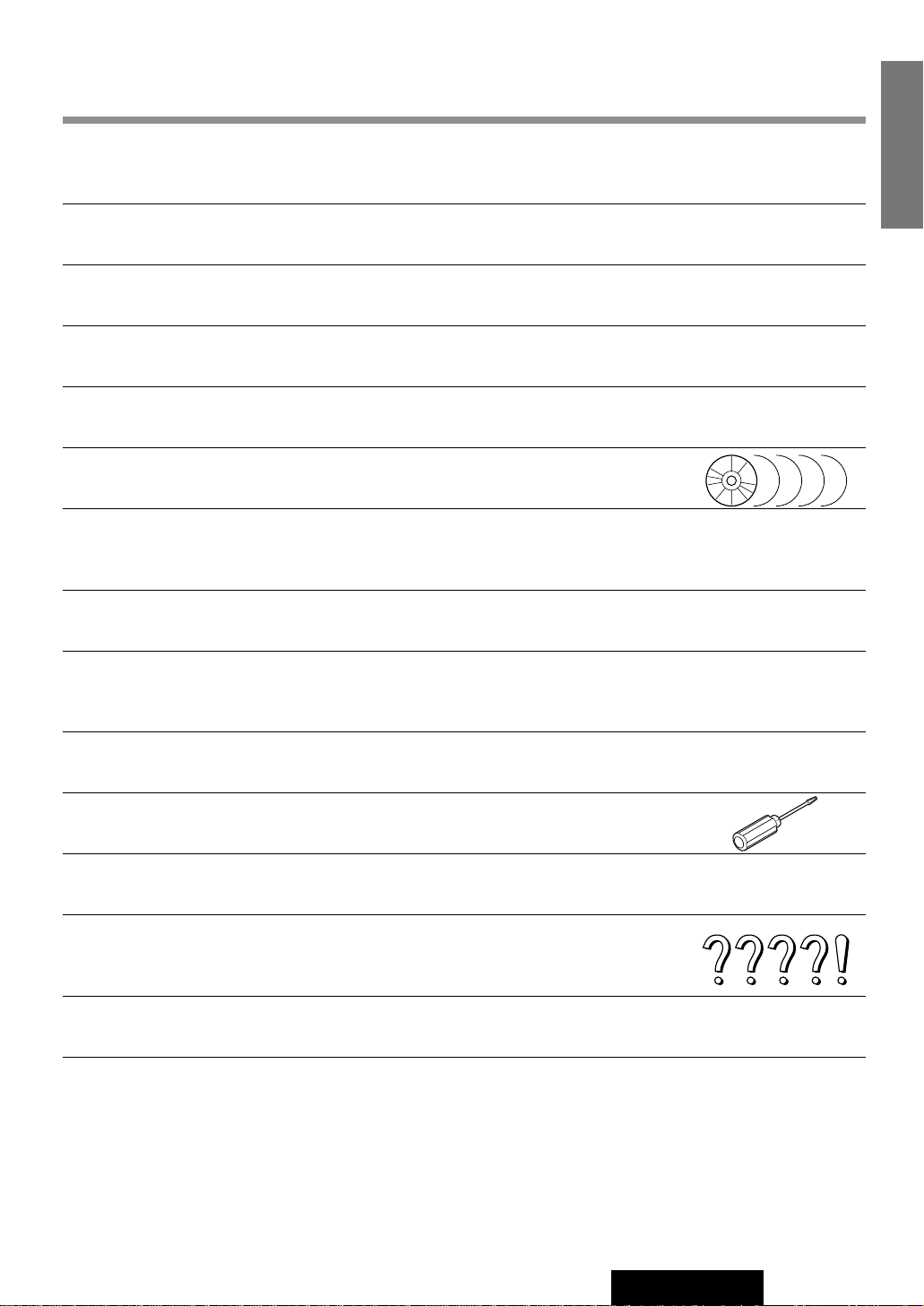
❏ Required Tools
You’ll need a screwdriver and the following:
❏ Dashboard Specifications
❏ Identify All Leads
The first step in installation is to identify all the car
wires you’ll use when hooking up your LCD monitor.
As you identify each wire, we suggest that you label
it using masking tape and a permanent marker. This
will help avoid confusion when making connections
later.
Note: Do not connect the power connector to the
display unit until you have made all connections. If
there are no plastic caps on the hooking wires, insulate all exposed leads with electrical tape until you
are ready to use them. Identify the leads in the following order.
12 V DC
Test Bulb
Electrical
Tape
Side-Cut
Pliers
THICKNESS
MIN. 3/16" (4.75 mm)
MAX. 7/32" (5.56 mm)
2-3/32" (53 mm)
7-5/32" (182 mm)
Page 33

36
CY-VMC7000U
27
E
N
G
L
I
S
H
Installation Guide (continued)
Power Lead
If your car has a radio or is pre-wired for one :
Cut the connector wires one at a time from the plug
(leaving the leads as long as possible) so that you
can work with individual leads. Turn the ignition on
to the accessory position, and ground one lead of
the test bulb to the chassis.
Touch the other lead of the test bulb to each of the
exposed wires from the cut radio connector plug.
Touch one wire at a time until you find the outlet that
causes the test bulb to light.
Now turn the ignition off and then on. If the bulb also
turns off and on, that outlet is the car power lead.
If your car is not wired for an audio unit :
Go to the fuse block and find the fuse port for
accessory (ACC) or ignition (IGN).
Battery Lead
If your stereo unit has a yellow lead, you will need to
locate the car's battery lead. Otherwise you may
ignore this procedure. (The yellow battery lead provides continuous power to maintain a clock, memory
storage, or other functions.)
If your car has a radio or is pre-wired for one:
With the ignition and headlights off, identify the car
battery lead by grounding one lead of the test bulb
to the chassis and checking the remaining exposed
wires from the cut radio connector plug.
If your car is not wired for an audio unit :
Go to the fuse block and find the fuse port for the
battery, usually marked BAT.
❏ Connect All Leads
Now that you have identified all the wires in the car,
you're ready to begin connecting them to the LCD
monitor wires. The connection diagram (B page
42) shows the proper connections and color coding
of the leads.
We strongly recommend that you test the unit
before making a final installation.
You can set the unit on the floor and make temporary connections to test the unit. Use electrical tape
to cover all exposed wires.
Important: Connect the red power lead last, after
you have made and insulated all other connections.
Ground
Connect the black ground lead of the power connector to the metal car chassis.
Battery
Connect the yellow battery lead to the correct radio
wire or to the battery fuse port on the fuse block.
Equipment
Connect any optional equipment such as an DVD
video player according to the instructions furnished
with the equipment. Read the operating and installation instructions of any equipment you will connect
to this unit.
Power
Connect the red power lead to the correct car radio
wire or to the appropriate fuse port on the fuse
block.
If the LCD monitor functions properly with all these
connections made, disconnect the wires and proceed to the final installation.
❏ Final Installation
Lead Connections
Connect all wires, making sure that each connection
is insulated and secure. Bundle all loose wires and
fasten them with tape so they won't fall down later.
Now insert the LCD monitor into the mounting collar.
Congratulations! After making a few final checks,
you’re ready to enjoy your new LCD monitor.
❏ Final Checks
1. Make sure that all wires are properly connected and insulated.
2. Make sure that the LCD monitor is securely
held in the mounting collar.
3. Tur n on the ignition to check the unit for proper operation.
If you have difficulties, consult your nearest authorized professional installer for assistance.
Page 34

37
CY-VMC7000U
28
E
N
G
L
I
S
H
¡We strongly recommend that you wear gloves for installation work to protect yourself from injuries.
¡When bending the mounting tab of the mounting collar with a screwdriver, be careful not to injure your
hands and fingers.
Caution : Do not disconnect the battery terminals of a car with trip or navigational computer since all user
settings stored in memory will be lost. Instead take extra care with installing the unit to prevent shorts.
Caution : Please follow the laws and regulations of your state, province or country for installation of the
unit.
¡Disconnect the cable from the negative (–) battery
terminal (see caution below).
¡Unit should be installed in a horizontal position
with the front end up at a convenient angle, but
not more than 30°.
less than 30°
❏ Transportation bracket removal
Be sure to remove the transportation brackets before use (installation).
Use Binding-Head Screws (M5 x 6 mm) for installation.
Be careful not to lose these Binding-Head Screws.
Display Unit
Binding-Head
Screws
(M5 x 6 mm)
Binding-Head
Screws
(M5 x 6 mm)
Transportation
Bracket
Transportation
Bracket
Mounting the Display Unit
❏ Precautions
This unit should be professionally installed. In case of difficulty, please consult with your nearest professional installer.
1. This unit only operates in a 12-volt DC negative ground system.
2. Follow the electrical connections carefully (a page 42 to 47). Failure to do so may result in damage to the unit.
3. Connect the power lead after all other connections are made.
4. Be sure to connect the battery lead (yellow) to the positive terminal (+) of the battery or fuse block (BAT) terminal.
5. Insulate all exposed wires to prevent short circuiting.
6. Secure all loose wires after installing the unit.
7. Please carefully read the operating and installation instructions of the respective equipment before connecting it to this
unit.
Page 35

38
CY-VMC7000U
29
E
N
G
L
I
S
H
Installation Guide (continued)
!6 Power Connector
Insert the Mounting Collar w into the
dashboard, and bend the mounting
tabs out with a screwdriver.
1
e Mounting
Spring
!1 Flat-Head Screw
t Mounting Bolt
3
Insert Trim Plate q.
4
After installation
reconnect the negative
(–) battery terminal.
5
Attach the Mounting Springs e
to the display unit.
2
!9 Display Unit/Control Unit
Connecting Cord
Secure the rear of the unit.
Fix the rear of the unit to the car body by either
method (a) or (b) shown at right after fixing
Power Connector !6 and Display Unit/Control
Unit Connecting Cord !9.
❏ Installation Procedures
(When using Mounting Collar w)
w Mounting Collar
Dashboard
Tab
Fastening the Mounting Collar
The tabs to be bent vary depending on the car.
Bend them with a screwdriver to fasten the
Mounting Collar w securely in the dashboard.
Page 36

39
CY-VMC7000U
30
E
N
G
L
I
S
H
(a) Using the Rear Support Strap o
(b) Using the Rubber Pad r
r Rubber Pad
t Mounting Bolt (M5)
Display Unit
Bracket
(On car)
u Washer
Assembling
Hex. Bolt
(M5 x 10
mm)
i Washer Assembling Hex.
Bolt
(M
6 x 20 mm)
Fire wall of car
Drill a hole 6.5 to 7 mm
in diameter.
y Flange Nut
(M6)
Display Unit
o Rear Support Strap
❏ Installation Procedures (When not using Mounting Collar w)
Use the brackets supplied with your car when mounting this unit. The bracket shape and mounting method vary with car
manufacturers, car types and manufacturing year. Please consult your nearest Panasonic Servicenter for details.
Select mounting screws according to the hole positions and hole shape of the bracket.
!1
Flat-Head Screw (M5 x 6 mm) 4 pieces
!2 Binding-Head Screw (M4 x 3 mm)
4 pieces
!0 Binding-Head Screw (M5 x 6 mm) 2 pieces
Recycle the Binding-Head Screws that fixed the transportation brackets for two more
positions.
When using these
mounting holes
Page 37

40
CY-VMC7000U
31
E
N
G
L
I
S
H
Mounting Example
Stick Velcro Tape !5 on the carpet and
mount the control unit on it.
Notes:
¡Never mount the control unit in any of the following locations to avoid damage due to overheating:
1. Near the heater port.
2. Places like the dashboard or rear deck, where it may be exposed to direct sunlight.
¡Do not mount the control unit near the door, where it could be exposed to rain.
Control Unit
!5 Velcro Tape
Carpet
Note: Some carpet materials may not be suitable for this mounting method. In this case,
please contact your nearest Panasonic
Servicenter for installation.
Mounting the Control Unit
Installation Guide (continued)
Use the supplied Spacer !3 if mounting hole of your car is shaped like below.
Display Unit
!3 Spacer
!4 Double-Faced Adhesive Tape
!0 Binding-Head Screw
(M5 x 6 mm)
Not used
Bracket
Mounting Hole of
a Bracket
(in section)
Existing Bracket (R)
(Bracket originally
attached to the car)
!4 Double-Faced
Adhesive Tape
Existing Bracket (L)
!0 Binding-Head Screw
(M5 x 6 mm)
!3 Spacer
Page 38

41
CY-VMC7000U
32
E
N
G
L
I
S
H
q Push the right and left clamp plates outward, one at a time, and pull the display unit toward yourself.
w After removing the right and left clamp plates, pull the unit with both hands till it comes off.
Push here to
remove the
clamp plates.
Before mounting the speaker, wipe a drop of water, dust and
an oil stain off from the place where the speaker should be
mounted to enhance adhesive strength.
Cautions :
¡Do not install the speaker in a location which
obstructs operation of the air bag or other safety
equipment.
¡Do not leave a credit card or other magnetic cards
near the speaker to avoid damaging the cards.
Mounting the Speaker
To Remove the Display Unit
@1 Clamp
Speaker
@0 Double-Faced
Adhesive Tape
q
w
Page 39

VIDEO-CONT
REVERSE
SIDEBRAKE
BATTERY5A
ACC
PRE-OUT
SPEAKER
!6 Power Connector
Ground Lead
To a clean, bare metallic
part of the car chassis
Battery Lead
To the car battery,
continuous +12V DC
Video Control Lead
To the Video Control lead of
the Panasonic car navigation
system (not available yet)
Power Lead
To ACC power, +12V DC
(Green / yellow stripe)
(Fuse 5A)
(Yellow)
(Red)
(Black)
(Bule / yellow stripe)
(Violet / white stripe)
(Resistor 220Ω)
Reverse Lead
When connecting the rear
view camera, use the reverse
lead. (a page 47)
Side Brake (Parking Brake)
Connection Lead
Be sure to wire the parking
brake for safety and preventing
accidents. (a page 46)
(Black)
(Black)
(Black / green stripe)
Speaker Lead
Pre-out Cord
(R) (Red)
(L) (White)
RGB Input Cord
To the RGB Connector of the Panasonic
car navigation system (not available yet)
!9 Display Unit / Control Unit Connecting Cord
REMOTE-OUT
CY-VMC7000U
Display Unit (Rear)
Use a Reverse Extension Cord
!7 if needed.
!
@
42
CY-VMC7000U
33
E
N
G
L
I
S
H
Electrical Connections
Cautions:
¡This product is designed to operate off a 12 volt, negative ground battery system.
¡To prevent damage to the unit, be sure to follow the connection diagram below.
¡Remove approx. 1/4" (5mm) of protective covering from the ends of the leads before connecting.
¡Do not insert the power connector into the unit until the wiring is completed.
¡Be sure to insulate any exposed wires from a possible short-circuit from the car chassis. Bundle all cables and keep
cable terminals free from touching any metal parts.
¡Remember, if your car has a drive computer or a navigation computer, the data of its memory may be erased when
the battery terminals are disconnected.
Wiring Diagram
No.
Item
Q'ty
!6
Power Connector
1
Supplied Hardware
!7
Reverse Extension
Cord
1
!8
Clip Connector
1
!9
Display Unit / Control
Unit Connecting Cord
1
Page 40

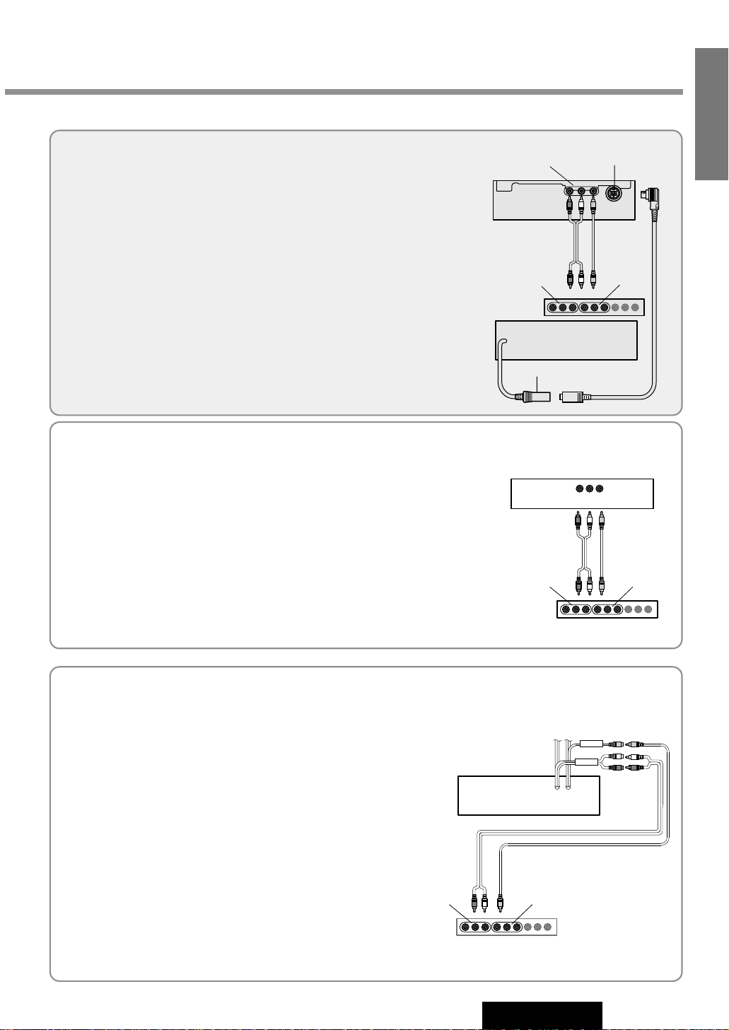
Connector Point
Video input terminal 1 (VTR1-IN)
Connects a VCR, camcorder, rear view
camera, other brand’s car navigation
system, and so on. (a page 46)
Video input terminal 2 (VTR2-IN)
Connects a VCR, camcorder, rear view
camera, other brand’s car navigation
system, and so on. (a page 46)
Video output terminal
Connects the second
monitor. (a page 44)
Panasonic
(Black)
(Black / green stripe)
Speaker
(supplied to
CY-VMC7000U)
Remote Control Signal
Receiver Cord
To the REMOTE-IN terminal
or Remote Control Signal
Receiver Cord of the
Panasonic DVD video player
CY-VMC7000U
Control Unit (Rear)
CY-VMC7000U
Control Unit
(Front)
Leave the cover
unremoved if you do not
connect the AV Control
Unit (CA-TU7000U)
Connect AV control unit with
receiver (CA-TU7000U).
Cautions:
¡Ask a qualified service person for installation and wiring.
The installation and wiring of this unit requires special skills and experience. For safety, ask the store where you purchased it to perform installation and wiring.
¡Do Not Disassemble or Modify.
Do not disassemble or modify the unit. Do not remove the coverings from the ends of cables and wires to provide
power for other devices. Because it may generate smoke or fire, and cause electric shock or trouble.
43
CY-VMC7000U
34
E
N
G
L
I
S
H
Notes:
¡Be sure to fully plug in the connector.
¡Install the cord to avoid high-temperature sports and secure with clamps and tape.
¡When game devices are connected, the image may be unstable.
¡When removing the DIN plug, be sure to press the clip.
Page 41

44
CY-VMC7000U
35
E
N
G
L
I
S
H
CY-VMC7000U
Display Unit (Rear)
CY-VMC7000U
Control Unit (Rear)
CY-VMC7000U
Control Unit (Front)
!6 Power Connector
Pre-Out Cord
PREOUT
RCA Cord
(Option)
RCA Cord (Option)
RCA Cord (Option)
(R) (Red)
(L) (White)
(Video)
(Yellow)
(R)
(Red)
(R)
(Red)
(Video)
(Yellow)
(L)
(White)
(L)
(White)
RCA Cord (Option)
!9 Display Unit / Control
Unit Connecting Cord
Electrical Connections (continued)
Example: Connection with DVD Player / Receiver
(CQ-DVR909U) and Rear Seat Monitor
Page 42

45
CY-VMC7000U
36
E
N
G
L
I
S
H
(R) (Red)
(R) (Red)
(L) (White)
(L) (White)
AUX-IN
AUX Input Cord
Video Output Cord
FRONT
Pre-Out Cord (Front)
Power Connector
(Supplied to CQ-DVR909U)
VTR-OUT
(Video) (Yellow)
DVD Player/Receiver
CQ-DVR909U
Rear Seat Monitor
Power Amplifier Unit
(Supplied to CQ-DVR909U)
(R)
(Red)
(Video)
(Yellow)
(L)
(White)
Audio
Left
Right
Video
output
Note: Refer to the operating instructions for the connected devices, in addition.
Page 43

46
CY-VMC7000U
37
E
N
G
L
I
S
H
Electrical Connections (continued)
Parking Brake
Foot Brake
–
+
Parking Brake Switch
Battery
Vehicle Chassis
Brake Light
!8 Clip
Connector
SIDE BRAKE
The parking brake switch position varies
with the vehicle model.
Side Brake (Parking Brake) Connection Lead (Blue / yellow stripe)
When the parking brake lever is engaged, the unit is grounded by the chassis.
q
Attach a Clip Connector !8 to the end of the parking
brake connection lead.
w The Clip Connector !8 is connected to the power
source side lead of the parking brake lever.
Comes up to this point
Side Brake (Parking Brake) Connection Lead
(Blue / yellow stripe)
Power Source Side Lead
Caution: For safety, be sure to ask your nearest professional installer to do this connection.
CY-VMC7000U
Control Unit
(Front)
(R)
(Red)
(R)
(Red)
(Video)
(Yellow)
(Video)
(Yellow)
(L)
(White)
(L)
(White)
Audio
Left
Right
Video
output
RCA Cord (Option)
INTELLIGENT SYSTEM
BS G-CODE
POWER
Connection with VCR or Camcorder
Connecting the Parking Brake Connection Lead
Note: Refer to the operating instructions for the connected devices, in addition.
Page 44

47
CY-VMC7000U
38
E
N
G
L
I
S
H
P
R
N
D
2
L
P
a
n
a
s
o
n
i
c
REVERSE
CY-VMC7000U
Control Unit
(Front)
CY-VMC7000U
Display Unit
(Rear)
!6 Power Connector
(Video)
(Yellow)
Rear View Camera
Rear View Camera
Control Unit
(Video)
(Yellow)
Video output
Camera input
RCA Cord (Option)
Reverse Lead
(Violet / white stripe)
Reverse Lamp
Clip Connector
Battery
Vehicle Chassis
Transmission Gear
Cut here
Check the reverse lamp.
*
Take it out of the back of the tail lamp mount.
Connecting the Reverse Lead
* In case using an optional rear view camera, the reverse
lead must be connected.
¡Connect the reverse lead (violet / white stripe) to the posi-
tive (+) lead of the reverse lamp (the lamp with a clear lens
that lights when the transmission gear is shifted into the
reverse position).
Notes: ¡Connect the reverse lead after cutting the terminal at the end.
¡Use a Reverse Extension Cord !7 if needed.
Connection with Rear View Camera
Note: Refer to the operating instructions for the connected devices, in addition.
Page 45

Troubleshooting
Preliminary Steps
Check and take steps as described in the tables below.
If You Suspect Something Wrong
Immediately switch power off.
Disconnect the power cable and check that there is neither smoke
nor heat from the unit before asking for repairs. Never try to repair
the unit yourself because it is dangerous to do so.
Cautions:
¡Do not use the unit if it malfunctions or is
something wrong.
¡Do not use the unit in an irregular condi-
tion, for example, without sound, or with
smoke or foul smell, can cause ignition or
electric shock. Immediately stop using it
and call the store where you purchased it.
48
CY-VMC7000U
39
E
N
G
L
I
S
H
■Common
Symptom Check / Remedy
No power
No sound
Condensation (dew)
aWait for a while before use.
Speakers setting is set to OFF.
aSet it to other than OFF.
Cables are not correctly connected.
aConnect cables correctly.
Mute is set to ON.
aSet it to OFF.
The volume is adjusted to zero.
aRaise the volume.
Fuse is burnt.
aCall the store where you purchased the unit, or your nearest Panasonic
Servicenter (see the attached sheet) and ask for fuse replacement.
Grounding wire is not correctly connected.
aConnect the grounding wire to a metal part of your car.
Accessory cable is not correctly connected.
aConnect the accessory cable to your car's ACC source.
Battery cable is not correctly connected.
aConnect the battery cable to the terminal that is always live.
Cables are not correctly connected.
aConnect cables correctly.
Car’s engine switch is not on.
aTurn your car’s ignition switch to ACC or ON.
Page 46

49
CY-VMC7000U
40
E
N
G
L
I
S
H
Symptom Check / Remedy
You are using a cellular phone near the unit.
aKeep some space between the unit and your cellular phone.
You did not pull the parking brake lever.
aPull the parking brake lever.
Side brake cord is not correctly connected.
aConnect the side brake cord correctly.
Only sound,
no picture.
Noise
Picture is not clear.
Symptom Check / Remedy
¡CD is defective.
¡Mechanical trouble.
aPress [u]. If failure persists, press the reset switch. If normal operation
is not restored, call the store where you purchased the unit or the nearest
Panasonic Servicenter to ask for repairs.
Unstable mounting.
aMount the unit securely with the mounting parts, referring to the section on
Installation.
Mounting angle is over 30 degrees.
aAdjust mounting angle to less than 30 degrees.
CD is dirty.
aClean CD, referring to the section on Notes on CD.
CD is dirty.
aClean CD, referring to the section on Notes on CD.
CD is upside down.
aPlace CD in the correction direction, the label side up.
CD is inside but no
sound.
CD sound skips, tone
quality is low.
Sound skip due to
vibration.
■CD
Symptom Check / Remedy
The monitor stops on the way to the home position for some reason.
aRaise the monitor a little and press [ ] (OPEN/CLOSE).
The monitor direction is not proper.
aChange the monitor direction to the center.
There is an obstacle.
aInstall the unit where the unit moves freely.
The tilt angle or the
front-rear position of the
display is not
adjustable.
The monitor does not
go back into the unit.
■Monitor
CD is not ejected.
Page 47

50
CY-VMC7000U
41
E
N
G
L
I
S
H
Troubleshooting (continued)
Symptom Check / Remedy
The picture from a car
navigation system is
not displayed.
The picture from a VCR or a
camcorder is not displayed.
The picture from a rear
view camera is not displayed.
The picture or the sound
of the second monitor is
not switchable.
“AUTO” is not selected for the setting of a rear monitor.
aSelect “AUTO” for the setting.
Input setting of a camera is not correct.
aMake the input setting correct.
Rear view camera is not connected correctly.
aConnect a rear view camera correctly.
A VCR or Camcorder is not connected correctly.
aConnect a VCR or Camcorder correctly.
The connection of a DVD player is not correct.
aConnect it correctly.
Input setting of a car navigation system is not correct.
aMake the input setting correct.
The connection of a car navigation system is not correct.
aConnect it correctly.
Symptom Check / Remedy
The brightness of the
screen is not stable.
This is a characteristic of liquid crystal panels and is not a problem.
The screen is not adjusted properly.
aMake every adjustment of the screen.
“AUTO” dimmer is selected.
aSelect one of the dimmer levels from among 1 to 4 to make the dimmer
adjustment become free from light intensity.
The picture is dark.
The picture is whitish.
Something is wrong
with the picture. The
picture is light in color.
Red, blue, or green
spots appears.
■
Car Navigation, DVD Player, VCR, Camcorder, Rear View Camera, Rear Monitor
■Display Settings
The picture from a DVD
player is not displayed.
Page 48

51
CY-VMC7000U
42
E
N
G
L
I
S
H
−E3−
NODISC
Display Check / Remedy
−E1−
−E2−
No disc is in the player.
aInsert disc into the CD slot.
No operation by some cause.
aPress [u]. If failure persists, press the reset switch. If normal operation
is not restored, call the store where you purchased the unit or the nearest
Panasonic Servicenter to ask for repairs.
Disc has scratches.
aCheck disc.
Disc is dirty, or is upside down.
aCheck disc.
Symptom Check / Remedy
Buttons are invalid for
operation.
Remote control is in the wrong direction.
aDirect the remote control at remote control sensor on the display unit.
Batteries have run down.
aReplace the batteries.
Wrong batteries.
aCheck the batteries.
Battery polarities (+) (–) are reversed.
aInsert the batteries correctly.
■Remote Control
Error Display Messages
■CD
Page 49

52
CY-VMC7000U
43
E
N
G
L
I
S
H
Troubleshooting (continued)
Maintenance
Your product is designed and manufactured to ensure a minimum of maintenance. Use a dry soft cloth for routine exterior
cleaning. Never use benzine, thinner or other solvents.
Product Servicing
If the suggestions in the charts do not solve the problem, we recommend that you take it to your nearest authorized
Panasonic Servicenter. The product should be serviced only by a qualified technician.
Replacing the Fuse
Use fuses of the same specified rating (5 amps). Using different substitutes or fuses with a higher rating, or connecting the
product directly without a fuse, could cause fire or damage to this unit.
If the replacement fuse fails, contact your nearest Panasonic Servicenter for service.
Reset Switch
Reset switch
Insert a hard, slender stick into the hole and push the switch.
The unit returns to the default state when the trouble is reset.
Remember, the data and settings stored in the memory are
deleted.
Important
Push the switch only when the unit fails to operate with any buttons.
If the unit fails to return to normal condition, call the nearest
Panasonic Servicenter and ask for repairs.
MENU MODE NAVI
NAVIGATION ASPECT
P·MODEPOWER
ASP
ENTER
CY-VMC7000U
DISC/BAND
TRACK/
YUNE
Page 50

53
CY-VMC7000U
44
E
N
G
L
I
S
H
Maintenance
To prevent damage to the system exterior
Do not apply pesticides, benzine, thinner or other volatile substances to the unit.
The cabinet surface primarily consists of plastic materials.
Do not wipe with benzine, thinner or similar substances because this will result in
discoloration or removal of the paint.
When a cloth with a cleansing chemical is used, follow the caution notes.
Do not leave the unit in contact with rubber or vinyl products for long periods of
time.
Do not use cleanser which have polishing granules because this could damage the
surface of the unit.
Alcohol
Pesticide
Wax
Tape
Adhesive
Tape
Benzine
Thinner
Clean dirt by wiping lightly with a soft cloth
When the unit is dirty, wipe the surface of the display using Wiping Cloth, an accessory to the unit.
■ Without a Wiping Cloth
When the unit is dirty, wipe with a well-wrung cloth dipped in a liquid dishwashing detergent (neutral) diluted with
water and then go over the same surface with a dry cloth.
(Since there is the possibility of water drops getting inside of the unit, do not directly apply cleanser to the surface.)
VOLUME
MENUMUTE MODE NAVI
NAVIGATION ASPECT
POWER
ASP
ENTER
DISC/BAND
TRACK/
CHANNEL
VOLUME
MENUMUTE MODE NAVI
NAVIGATION ASPECT
POWER
ASP
ENTER
DISC/BAND
TRACK/
CHANNEL
Wring well.
Wipe lightly.
Go over the same surface with a dry
cloth.
Kitchen cleanser diluted with water
aa
Caution: If water drops or similar wet substances get inside the monitor, it may cause a malfunction.
Page 51

54
CY-VMC7000U
45
E
N
G
L
I
S
H
Maintenance (continued)
Notes on CD
ONLY USE DISCS CARRYING THE LABEL
How to hold the CD
¡Do not touch the underside of the disc.
¡Do not make scratches on the disc.
¡Do not bend disc.
¡When not in use, keep CD in the case.
Do not use irregularly shaped CDs
Do not leave discs in the following places:
¡Direct sunlight
¡Near car heaters
¡Dirty, dusty and damp areas
¡Seats and dashboards
Disc Cleaning
Use a dry, soft cloth to wipe from the center outward.
Caution on New Discs
A new disc may have rough edges on its inner and outer
perimeter. These may cause malfunction.
Remove the rough edges using a pencil, etc.
Music
agsjbc ujniu imnmk
bhxujk kkmj ibi
abcde
Music
agsjbc ujniu imnmk
bhxujk kkmj ibi
abcde
Label side
Do not use irregularly shaped CDs
<Right> <Wrong>
Rough edge
A playable CD-R disc is only a CD-R disc on which sound was recorded.
¡Some recorded CD-R discs by using CD recorder are not playable because of their characteristic, or scratches or dirt on
the discs.
¡You can not play a CD-R disc that has not been finalized.
¡A CD-RW disc is not playable.
¡MP3 file, video CD, CD-ROM and CD-EX disc are not playable.
¡Be sure to observe the handling instructions of CD-R disc.
¡Do not apply a disc that has a label printed by a commercially available label printer.
Notes on CD-R Disc
Page 52

55
CY-VMC7000U
46
E
N
G
L
I
S
H
Specifications
General
Power Supply : DC 12 V (11 V - 16 V), test voltage 14.4 V, negative ground
Current Consumption : Less than 1.5 A
Maximum Power Output (External Speaker)
: 0.7 W
Compatible Speaker Impedance : 8 Ω
Video Input Signal : Composite video signal, 1.0 Vp-p (75 Ω)
Audio Input Sensitivity : 1.8 Vrms
Video Output Signal : Composite video signal, 1.0 Vp-p (75 Ω)
Pre-Amp Output Voltage : 1.8 Vrms (CD)
Pre-Amp Output Impedance : Less than 600 Ω
Dimensions (W x H x D)
Display Unit : 7” x 1-15/16” x 6-15/16” (178 x 50 x 160 mm)
Control Unit : 6” x 13/16” x 5-7/8” (153 x 21 x 150 mm)
Weight
Display Unit : 5 lbs. 1 oz. (2.3 kg)
Control Unit : 1 lbs. 5 oz. (0.6 kg)
Monitor
Liquid Crystal Panel : 7" wide
Screen Dimensions (W x H x D) : 6-1/16" x 3-7/16" x 6-15/16" (154 x 87 x 177 mm)
Number of Pixels : 336,960 pixels (234 vertical x 480 horizontal x 3)
Valid Pixel Ratio : Over 99.99%
Display Method : Transparent color filter format
Drive Method : TFT (Thin Film Transistor) active matrix format
Light Source : Internal light (Built-in small fluorescent lamp)
CD Player
Sampling Frequency : 8 times oversampling
DA Converter : MASH•1 bit/4 DAC System
Error Correction System : Panasonic Super Decoding Algorithm
Pick-Up Type : Astigma 3-beam
Light Source : Semiconductor Laser
Wave Length : 780 nm
Frequency Response : 20 Hz - 20 kHz (±1 dB)
Signal to Noise Ratio : 80 dB (IHF, A)
Total Harmonic Distortion : 0.05 % (1 kHz)
Wow and Flutter : Below measurable limits
Channel Separation : 80 dB
Supplied Speaker
Impedance : 8 Ω
Maximum Power Input : 2 W
Above specifications comply with EIA standards.
Note: Specifications and the design are subject to modification without notice due to improvements in technology.
 Loading...