

Page 1
Installation Instructions
Einbauanleitung
Instructions d’installation
Installatiehandleiding
Monteringsanvisningar
Istruzioni per l’installazione
Instrucciones de instalación
Installationsanvisninger
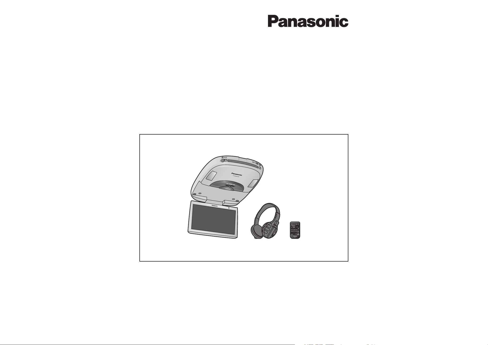
Overhead 9q Widescreen Color LCD Monitor with Built-in DVD Player
CY-VHD9401N
≥ Please read these instructions carefully before using this product and keep this manual for future reference.
≥ Bitte lesen Sie diese Bedienungsanleitung vor der Verwendung dieses Produktes aufmerksam durch und bewahren Sie sie
danach für spätere Nachschlagzwecke sorgfältig auf.
≥ Prière de lire ces instructions attentivement avant d’utiliser le produit et garder ce manuel pour l’utilisation ultérieure.
≥ Leest u deze instructie alstublieft zorgvuldig door voor u dit product in gebruik neemt en bewaar deze handleiding voor
later gebruik.
≥ Läs igenom denna bruksanvisning noga innan produkten tas i bruk. Spara bruksanvisningen för framtida behov.
≥
Si prega di leggere attentamente queste istruzioni prima di usare questo prodotto e di conservare questo manuale per usi futuri.
≥
Lea con atención estas instrucciones antes de utilizar el producto y guarde este manual para poderlo consultar en el futuro.
≥
Læs venligst denne brugsvejledning grundigt, inden dette produkt tages i brug og gem den til senere konsultation.
Page 2
2
CY-VHD9401N
E
N
G
L
I
S
H
CY-VHD9401N
3
E
N
G
L
I
S
H
Safety Information
∫ Read the operating instructions for the unit and
all other components of your car audio system
carefully before using the system. They contain
instructions about how to use the system in a
safe and effective manner. Panasonic assumes
no responsibility for any problems resulting from
failure to observe the instructions given in this
manual.
Warning
This pictograph intends to alert
you to the presence of important
operating instructions and
installation instructions. Failure to
heed the instructions may result in
severe injury or death.
∫ This manual uses pictographs to show you how to
use the product safely and to alert you to potential
dangers resulting from improper connections
and operations. The meaning of the pictographs
are explained below. It is important that you fully
understand the meanings of the pictographs in
order to use this manual and the system properly.
Caution
This pictograph intends to alert
you to the presence of important
operating instructions and installation
instructions. Failure to heed the
instructions may result in injury or
material damage.
Observe the following warnings when
installing.
q Do not, under any circumstances, install the
product in a place where the driver’s ability to
drive the car or the driver’s fi eld of vision will
be impaired.
Installing the product in a place where it will
interfere with the driver’s fi eld of vision either
in front or behind or in a place where it will
interfere with the driver’s ability to drive the car
may lead to traffi c accidents and/or injury.
q Have a professional technician wire and install
the product.
Professional skill and experience is required
to wire and install the product. Improper
installation could result in failure of safety
equipment resulting in accident and injury.
For safety’s sake, always ask the store from
which you purchased the product to install and
wire it for you.
q Use in DC 12 V - grounded vehicles.
This
product
is only for DC 12 V - grounded
vehicles. It cannot be used in DC 24 V vehicles
(such as large trucks, diesel vehicles designed
for cold climates, etc.).
Using this
product
in such vehicles could cause
fi re or other malfunction.
Warning
q Be sure to disconnect the battery’s - terminal
while wiring and installing the product.
Doing the wiring and installation with the
battery’s - terminal still connected could cause
electrical shock and injury due to a short circuit
accidents.
q Install the product securely so that it will not
shift out of place or drop down.
Loose screws or insecure installation may cause
the product to shift out of position or drop
down, etc. while the car is moving, resulting in
an accident and/or injury.
q Do not disassemble, repair or modify the
product.
Do not disassemble, repair or modify the
product, or cut the cord to connect it to the
power supply for another device. This could
cause fi re, electrical shock or other malfunction.
q Never use the car’s safety equipment for
installing or grounding the product.
Using the bolts, nuts and screws of the car’s
safety equipment (steering and brake systems,
fuel tank, etc.) could cause accidents. Follow
the instructions and only use the accessories
provided with the product and the specifi ed
parts.
q Install the product after checking the position
of the car’s pipes, tank and electrical wiring.
When opening holes in the car body to install
the
product
, be careful not to touch or interfere
with the pipes, tank or electrical wiring. Doing
so could cause fi re or accidents.
q Always use the accessories provided with the
product and the specifi ed parts.
Using parts other than those specifi ed could
damage the inside of the product or cause the
product to not be securely fastened and thus
come loose, which could cause accidents,
malfunction or fi re.
q Do not install the product in a location where
it will be subject to heavy vibration or in an
unstable location.
Installing the product in a sloping location or on
a noticeably curved surface, etc. may cause the
product to shift out of position or drop down,
etc. while the car is moving, resulting in an
accident and/or injury.
q Follow the instructions to install and wire the
product.
Failure to follow the instructions to properly
install and wire the product could cause
accidents or fi re.
q Run the cords so that they do not interfere with
driving or with entering or exiting the car.
Run the cords so that they do not wrap around
the steering wheel, gearshift, brake pedal, etc.
or around your legs, and secure all the cords
together. Failure to do so could cause accidents
or injury.
Observe the following warnings when
installing. (Continued)
q Do not install the product in a position where it
will interfere with the operation of the air bag.
The air bag may fail to operate properly or the
main unit or its parts could become dislodged
and end up fl ying through the air by an air bag
which has opened, causing an accident and/or
injury.
q Be sure to use fuses with the prescribed
capacity. Have a professional technician
replace the fuses.
Using fuses that exceed the prescribed capacity
could cause the
product
to start smoking, ignite
or otherwise malfunction. For replacement and
repair of fuses, contact the store from which you
purchased your
product
or a nearby Panasonic
Service Centre.
q Contact your car dealer or manufacturer
to determine the required procedure and
strictly follow their instructions before
attempting installation of this product if your
car is equipped with air bag and/or anti-theft
systems.
Specifi c procedures may be required for
connection and disconnection of the battery
to install this product. Failure to follow the
procedure may result in the unintended
deployment of air bags or activation of the
anti-theft system resulting in damage to the car
and personal injury.
Warning
NO WARRANTY
Panasonic shall have no liability for reduction in safety or any accident caused by installing this
product. We shall not guarantee any auto parts damaged during installation.
Page 3
4
CY-VHD9401N
E
N
G
L
I
S
H
CY-VHD9401N
5
E
N
G
L
I
S
H
Safety Information
(continued)
≥ The main unit weighs approximately 3 k . Be
absolutely sure that the main unit is secured
properly and does not come loose even with
vibration or shock.
≥ Check that there is suffi cient strength in the
ceiling reinforcement crosspieces to hold the
weight of the product.
≥ Check the thickness of the interior materials,
attachment space, etc, refer to the attachment
example (page 40) and determine the base plate
attachment position.
≥ Take care that the base plate or attachment
screws do not pinch cords and wiring. Also take
care not to scratch or damage the ceiling or
other parts of the vehicle.
Observe the following cautions when
using this unit or installing.
q If an RCA or similar cord is to be connected
to the product, adjust its position and length
so that it will not become entangled or come
into contact with your body. After use, be
absolutely sure to disconnect it from the
product.
Failure to heed this caution may result in an
accident and/or injury.
q Before connecting the product with another
device, consult the operating instructions
of the device concerned to ensure that the
product and device will be connected properly.
Incorrect connections may cause accidents
and/or malfunctioning.
Observe the following cautions when
replacing the bulb of the dome light.
≥ Have the dome light replaced by a qualifi ed
specialist.
≥ While you are replacing a bulb, be absolutely
sure to keep the dome light switch at OFF.
Otherwise, you may burn yourself.
≥ The bulb is very hot to touch while it is lighted
and immediately after it has gone off.
≥ Before attempting to replace it, turn the dome
light switch off, wait several minutes and then
check that it cooled off.
≥ Use a bulb with the specifi ed ratings (12 V/5 W).
Do not use any other bulb.
≥ Gripping the bulb with too much force may
break it. Wear fi ngerstalls or use some other
anti-slip method when replacing it.
Caution
Observe the following cautions when
installing.
q Do not damage the cords.
Wire breaks and short circuits can cause
electrical shock or fi re.
Run the cords so that they do not get tangled in
the moving parts (such as the seat rails), screws
or car body.
Do not damage, pull too hard, fold, twist, or
work on the cords. Do not place the cords near
heating appliances or put heavy objects on the
cords.
q Install the monitor in a position where it will
not hit anybody’s head when it opens and
closes.
Failure to heed this caution may result in an
accident and/or injury.
q Take care not to injure your fi ngers with the
power drill or other tool you are using. Also
take care not to damage the wiring near the
ceiling panel.
Failure to heed this caution may result in an
accident, injury and/or malfunctioning.
q Do not poke your fi ngers between the ceiling
and this product.
Failure to heed this caution may result in an
injury and/or malfunctioning of the product.
q Wear gloves for installation work to protect
yourself from injuries.
Failure to heed this caution may result in an
accident and/or injury.
q Take care that the wiring is not pinched or
caught by the base plate attached to the roof
or any other parts.
Failure to heed this caution may result in an
accident and/or injury.
q Before installing the unit, be absolutely sure to
check that the screws do not make any contact
with the ceiling panel.
If some space is required between the base plate
and the unit, attach and adjust the under cover.
For details on installing the under cover, consult
your dealer.
q Wear goggles or protective eyewear to shield
your eyes from airborne metal particles during
drilling.
Failure to heed this caution may result in an
accident and/or injury.
q As you cut the headliner, take care not to cut
your fi ngers. Also take care not to damage any
other areas of the headliner.
Failure to heed this caution may result in an
accident and/or injury.
q When fi tting the product, using the supplied
base plate, please ensure that it is properly
secured to avoid excessive vibration or the
chance of the product coming loose and
causing an accident.
q The metal plate, screws and nuts required to
attach the base plate are not supplied.
The parts required for attaching the product
differ depending on the vehicle type. Consult a
professional technician for more details, and
always have a professional technician wire
and install the product for you.
q Follow local rules and regulations for
installing the unit.
Observe the following cautions for
connections.
≥ To prevent damage to the unit, be sure to follow
the connection diagram.
≥ Do not connect the power connector to the unit
until the wiring is completed.
≥ When connecting stripped wires, be sure to
wrap them securely with electrical tape to
prevent shorts.
≥ Bundle all cables and keep cable terminals free
from touching any metal parts.
Observe the following cautions for
installing the base plate
≥ Do not install the base plate as fi gure on page
38.
One method for installing the main unit is to
use bond or adhesive tape (option) to fi x wood
or plastic (option) to the ceiling panel before
attaching the base plate. However, the main unit
will not be securely installed using this method,
and the bond may separate due to heat from
the vehicle. Shock, impact, vibration or main
unit weight in this situation would be extremely
dangerous.
Safety Information ........... Page 2
Before Installation ................ 34
Safety Installation Diagram ................ 34
Open the Display Unit......................... 35
Close the Display Unit ........................ 35
Display Unit Lateral Angle
Adjustment....................................... 35
Installation Guide................. 36
Supplied Hardware............................. 36
Installation..........................37
Introduction ....................................... 37
Correct Example of Base Plate
Installation ........................................39
Attachment Example
(without the Under Cover)................ 40
Attachment Example
(with the Under Cover)..................... 40
Work Flow.......................................... 41
Installation Procedures ...................... 41
Electrical Connections ........... 48
Wiring Diagram (Simple System)....... 48
Wiring Diagram
(Recommended System).................. 50
Wiring Diagram
(Advanced System).......................... 52
Contents
Note:
≥ For replacing the bulb of the dome light, please
refer to page 129 in the Operating Instructions.
Page 4
34
CY-VHD9401N
CY-VHD9401N
35
Before Installation
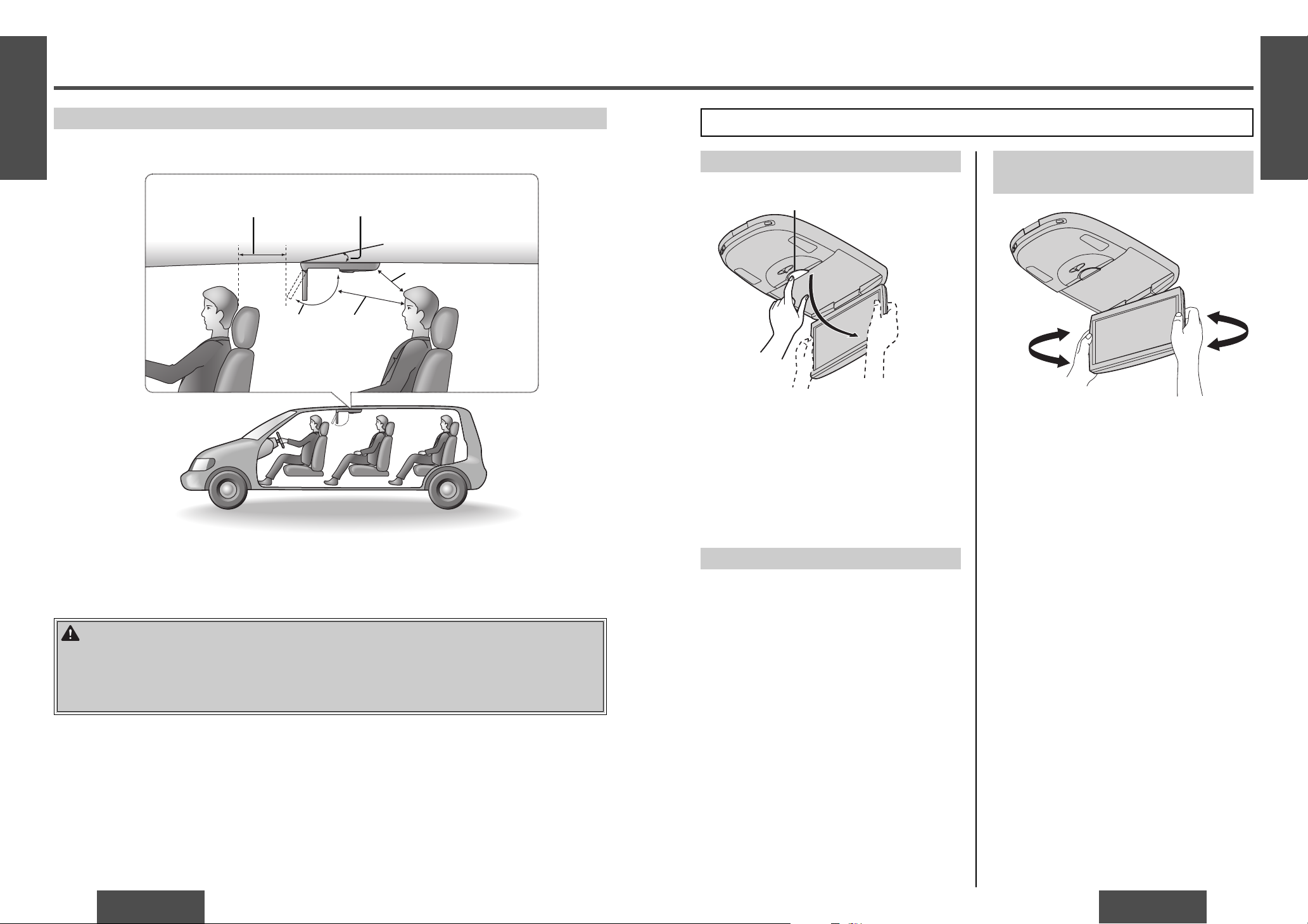
Display Unit Lateral Angle
Adjustment
You can swivel it to the left and right, 30˚ each way.
Hold the display unit by the non-slip part in the
upper half of it and adjust its lateral angle.
Open the Display Unit
1 Push the display release button [PUSH OPEN]
until the display is unlocked.
(Press the button with one hand while holding
the display with the other.)
2 Open the display unit by both hands until a
comfortable viewing angle is reached.
Close the Display Unit
Move the display unit by both hands until the
display release button is locked.
Note:
≥ Always use both hands to open or close the
display unit.
≥ Always check that the display release button is
locked after closing the display unit.
≥ If the display unit cannot be locked, be sure to
consult your dealer and remedy the situation.
[PUSH OPEN]
Safety Installation Diagram
≥ This unit opens and closes at the maximum dimensions given below.
WARNING:
Have a professional technician wire and install the product.
Professional skill and experience is required to wire and install the product. Improper installation could
result in failure of safety equipment resulting in accident and injury. For safety’s sake, always ask the
store from which you purchased the product to install and wire it for you.
Approximately 150 mm*
Approximately
300 mm
Maximum
120˚
Approximately 300 mm
* Install the product in such a way as to maintain
the distances shown even when the display unit
is rotated by 30˚ toward the front seat headrest
(page 35).
Installation angle: Less than 20˚
Perform the adjustment below in order to provide the installation range shown in the fi gure on the left.
Maximum
120x
30x
30x
E
N
G
L
I
S
H
1
E
N
G
L
I
S
H
2
Page 5
36
CY-VHD9401N
CY-VHD9401N
37
Installation Guide
Note:
≥ Various settings that have been stored in the
memory in other on-board equipment (car
navigation etc.) may be lost if the battery
terminals are disconnected.
Therefore, we recommend to make a record of or
to back up the settings before disconnecting the
terminals.
After completing installation of the main unit, set
the equipment again according to the record.
WARNING:
≥ Use in DC 12 V - ground vehicles. This
product is only for DC 12 V - grounded
vehicles. It cannot be used in DC 24 V
vehicles (such as large trucks, diesel
vehicles designed for cold climates, etc.).
Using this product in such vehicles could
cause fi re or other malfunction.
≥ Be sure to disconnect the battery’s
- terminal while wiring and installing the
product. Doing the wiring and installation
with the battery’s - terminal still connected
could cause electrical shock and injury due
to a short circuit accidents.
≥ Contact your car dealer or manufacturer
to determine the required procedure
and strictly follow their instructions
before attempting installation of this
product if your car is equipped with
air bag and/or anti-theft systems.
Specifi c procedures may be required for
connection and disconnection of the battery
to install this product. Failure to follow the
procedure may result in the unintended
deployment of air bags or activation of the
anti-theft system resulting in damage to the
car and personal injury.
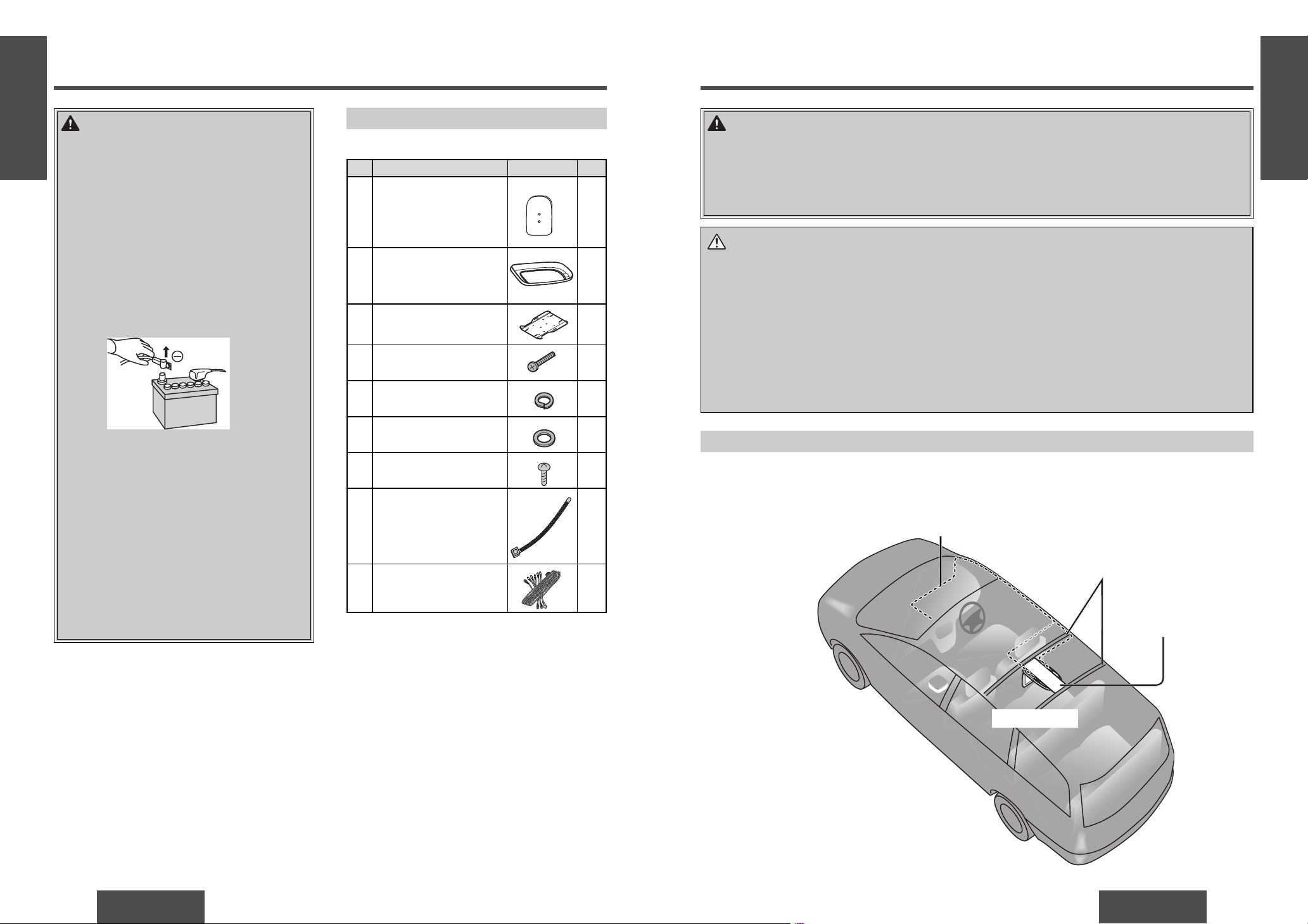
Supplied Hardware
No. Item Diagram Q’ty
1
Paper template
Printed on the inside of
the box.
1
2
Under cover 1
3
Base plate 1
4
Screw
(M5k25 mm)
6
5
Spring washer
(5 mm‡)
6
6
Flat washer
(5 mm‡)
6
7
Screw (for resin)
(2.6 mm‡k8 mm)
6
8
Cord clamp 2
9
Power connector 1
For Installation
Installation
WARNING:
Have a professional technician wire and install the product.
Professional skill and experience is required to wire and install the product. Improper installation could
result in failure of safety equipment resulting in accident and injury.
For safety’s sake, always ask the store from which you purchased the product to install and wire it for
you.
Introduction
A sample installation is shown below for your reference.
First remove the headliner. Next, fi rmly attach the metal plate (option) and the base plate to the two ceiling
reinforcement crosspieces. Finally replace the headliner as it was and attach the main unit.
Ceiling reinforcement
crosspieces
Wiring
Caution:
≥ Wear gloves for installation work to protect yourself from injuries. Failure to heed this caution may
result in an accident and/or injury.
≥ Wear goggles or protective eyewear to shield your eyes from airborne metal particles during drilling.
Failure to heed this caution may result in an accident and/or injury.
≥ When fi tting the product, using the supplied base plate, please ensure that it is properly secured to
avoid excessive vibration or the chance of the product coming loose and causing an accident.
≥ The metal plate, screws and nuts required to attach the base plate are not supplied.
The parts required for attaching the product differ depending on the vehicle type. Consult a
professional technician for more details, and always have a professional technician wire and install
the product for you.
CY-VHD9401N
Metal plate (option),
base plate
E
N
G
L
I
S
H
3
E
N
G
L
I
S
H
4
Page 6

38
CY-VHD9401N
CY-VHD9401N
39
Installation
(continued)
Ceiling panel
Ceiling panel
Nut
Maximum 500 mm
3 Base plate
3 Base plate
≥ The metal plate, screws and nuts required to
attach the base plate are not supplied.
The parts required for attaching the product
differ depending on the vehicle type. Consult a
professional technician for more details, and
always have a professional technician wire and
install the product for you.
≥ Do not install the base plate as fi gure on page
38. (Please see fi gure below.)
One method for installing the main unit is to
use bond or adhesive tape (option) to fi x wood
or plastic (option) to the ceiling panel before
attaching the base plate. However, the main
unit will not be securely installed using this
method, and the bond may separate due to
heat from the vehicle. Shock, impact, vibration
or main unit weight in this situation would be
extremely dangerous.
≥ The main unit weighs approximately 3 k . Be
absolutely sure that the main unit is secured
properly and does not come loose even with
vibration or shock.
≥ Check that there is suffi cient strength in the
ceiling reinforcement crosspieces to hold the
weight of the product.
≥ Check the thickness of the interior materials,
attachment space, etc, refer to the attachment
example (page 40) and determine the base
plate attachment position.
≥ Take care that the base plate or attachment
screws do not pinch cords and wiring. Also take
care not to scratch or damage the ceiling or
other parts of the vehicle.
Do not install the base plate as follows.
≥ Do not use wood or plastic attachment
boards.
≥ Do not attach the base plate directly onto
the ceiling panel using bond or adhesive
tape.
The main unit will not be securely installed
using this method, and the bond may
separate due to heat from the vehicle.
Shock, impact, vibration or main unit
weight in this situation would be extremely
dangerous.
≥ Do not use self-tapping screws to attach the
base plate.
Correct Example of Base Plate Installation
Ceiling reinforcement crosspieces
≥ Check that there is suffi cient strength in the
ceiling reinforcement crosspieces to hold the
weight of the product.
Metal plate
≥ Do not attach the metal plate directly onto
the ceiling panel. Attach it to the ceiling
reinforcement crosspieces.
≥ The metal plate should have the following
characteristics.
· Bent reinforced section on both sides
· Thickness of 1.6 mm or more
Screws
≥ Use screws to attach the metal plate, and
securely fasten the nuts.
Be absolutely sure that the screws are not
loose after fastening.
≥ Use at least 2 screws (option) on each side (a
total of at least 4), and be absolutely sure that
the screws are not loose after fastening.
Screws
≥ Use at least 2 screws (option) on each side (a
total of at least 4), and be absolutely sure that
the screws are not loose after fastening.
Caution on installing the base plate:
E
N
G
L
I
S
H
5
E
N
G
L
I
S
H
6
Page 7

40
CY-VHD9401N
CY-VHD9401N
41
Installation
(continued)
Installation Procedures
Remove the headliner from the vehicle for installation.
1
Remove the interior headliner from the car in
which the unit is to be installed while taking
care not to damage the interior or its fi ttings.
2 Now remove the dome light but leave its wiring
in place.
1
Note:
≥ Headliner construction and the position of chassis
lights vary depending on the type of vehicle. Do a
preliminary check before starting work.
Note:
≥ The fi gure below shows installation in a simplifi ed
way. Do not rely on this fi gure alone as the basis
for installation. Instead, be sure to follow the
procedure on the following pages.
2
Attach the metal plate (option)
and the base plate to the ceiling
reinforcement crosspieces
(page 42).
3
Wire the unit and replace the
headliner (page 43, 44).
5
Connect the wires and attach the
main unit (page 46, 47).
4
Get ready to attach the main unit
(page 45).
There are fi ve main steps to install the main unit.
For each step, follow the detailed procedures on
page 41`47.
Ceiling reinforcement crosspieces
Front cover
CY-VHD9401N
1
Remove the headliner from the
vehicle for installation (page 41).
Work Flow
Ceiling panel
Use the screws (for resin) (7) to attach the
accessory under cover (2) to the underside of
the main unit.
If some space is required between the base plate and the unit, attach the under
cover and adjust as follows.
7 Screw
(2.6 mm‡ k 8 mm) a 6
2 Under cover
Note:
≥ Depending on the type of vehicle, there may be
differences in the gap between the headliner
and the main unit. For gaps, adjust the under
cover and screw as necessary.
Attachment Example (without the Under Cover)
Attachment Example (with the Under Cover)
Headliner
3 Base plate
3 Base plate
Headliner
2 Under cover
E
N
G
L
I
S
H
7
E
N
G
L
I
S
H
8
Page 8

42
CY-VHD9401N
CY-VHD9401N
43
Installation
(continued)
2 Put the headliner that was removed earlier back
in its original place.
3 In the re-attached headliner, locate the center
position of the base plate which has been
attached to the reinforcement crosspieces,
and cut out the section that will expose the
reference holes to view.
Caution:
≥ As you cut the headliner, take care not
to cut your fi ngers. Also take care not to
damage any other areas of the headliner.
Failure to heed this caution may result in
an accident and/or injury.
Headliner
Reference holes
3
Wire the unit and replace the headliner.
1
Connect the wiring of the dome light and
the unit, and bring the wiring as far as the
installation position.
Caution:
≥ Pass the wiring you have brought to the
installation position through the pullout
openings in the base plate. Take care
that the wiring is not pinched or caught
by the top of the base plate.
Pullout openings
Base plate top
Note for connecting the dome lights
(page 48s49):
≥ There are two common types of dome
light circuits used, positive or negative
switched.
Positive systems supply voltage to the
interior lights to turn them on, negative
switched systems apply ground to
illuminate the bulbs.
≥ The dome light lead connection varies
depending on the type of vehicle. Consult
a service technician as needed.
≥ Both positive and negative switched
light circuits are supported by this
unit’s door switch. If the door switch
is not wired correctly, the dome
light will not come on properly.
The polarity differs from one model to
another so be absolutely sure to ask a
dealer or service technician to wire and
install the unit.
4 Use the tool such as a power drill to drill holes
in the ceiling reinforcement crosspieces to meet
the mounting holes on the assembled plates.
Caution:
≥ Before drilling the holes, check exactly
where the unit and bracket are to be
installed. Take care not to injure your
fi ngers with the power drill or other tool
you are using. Also take care not to
damage the ceiling panel.
≥ Wear goggles or protective eyewear to
shield your eyes from airborne metal
particles during drilling. Failure to heed
this caution may result in an accident
and/or injury.
5 Affi x the assembled plates to the ceiling
reinforcement crosspieces securely using the
screws and nut (option).
4
2
Attach the metal plate (option) and the base plate to the ceiling
reinforcement crosspieces.
Nut (option) a 6
1 Carefully check the position of the ceiling
reinforcement crosspieces and determine where
the main unit will be installed.
2 Decide the position for attaching the base
plate on the metal plate (option). Attach it
by screwing in the screws (option) and nuts
(option) in 4 positions.
3 Use an indelible marker to mark 4 positions on
the ceiling reinforcement crosspieces where
you will drill holes to attach the assembled
plates.
Ceiling reinforcement crosspieces
Assembled
plates
Nut (option) a 4
Screw (option) a 4
Screw (option) a 6
Tool such as a power drill
Note:
≥ Use at least 2 screws (option) on each side (a
total of at least 4), and be absolutely sure that
the screws are not loose after fastening.
Note:
≥ Use at least 2 screws (option) on each side (a
total of at least 4), and be absolutely sure that
the screws are not loose after fastening.
E
N
G
L
I
S
H
9
E
N
G
L
I
S
H
10
Page 9

44
CY-VHD9401N
CY-VHD9401N
45
Installation
(continued)
Note:
≥ Be careful not to scratch the surface of the
front cover when removing it.
≥ The screws you remove now will be needed
when you re-attach it to complete installation.
Keep them in a place where they will not be
lost.
Caution:
≥ Before installing the unit, be absolutely
sure to check that the screws do not
make any contact with the ceiling panel.
If some space is required between the
base plate and the unit, attach and adjust
the under cover (page 40). For details on
installing the under cover, consult your
dealer.
2 Insert the screws (4), fl at washer (6),
and spring washers (5) in the main unit.
Keep the screws only loosely tightened until the
unit is attached to the base plate.
6 Flat washer
(5 mm‡)
5 Spring washer
(5 mm‡)
4 Screw (M5a25 mm)
Front cover
4 Screw a 6
5 Spring washer a 6
6 Flat washer a 6
* Depending on the type of vehicle for the
installation, you may not need to use some
space washers. When the space washers
are to be used, make absolutely sure
that their height will be the same in all
6 locations. Consult your dealer for details.
4
Get ready to attach the main unit.
1
Open the display unit and remove the 2 screws.
Place your fi ngers at A (in 2 places) on the
panel, and slowly pull down the panel.
5 Align the guide holes in the accessory paper
template (1) with the reference holes which
can be seen from the section that was cut
out from the headliner, and paste the paper
template onto the headliner using a tape or
other thing.
Note:
≥ Before cutting the headliner, check the
direction of the paper template to prevent any
mistakes in the installation position.
1 Paper template
Cut out
Front side
Rear side
6 Pull out the wires that you pulled from the
pullout opening of the base plate beforehand so
that it will be easier to wire.
4 Cut out the paper template (1) printed on the
inside of the individual packing box.
E
N
G
L
I
S
H
11
E
N
G
L
I
S
H
12
A
A
A
Page 10

46
CY-VHD9401N
CY-VHD9401N
47
Installation
(continued)
3 Insert the bosses of the main unit underside in
the base plate guide holes.
4 Use a screwdriver to tighten the screws
(in 6 positions) that you previously tightened
loosely to secure fi rmly the main unit.
5 Insert the end of the panel, and push it
back into place as shown in the fi gure.
Secure the screws.
Note:
≥ Be careful not to scratch the surface of
the front cover when attaching it.
1 Connect the wires (page 48 to 53) which
were pulled out in a previous step to the unit
(page 43`44).
2 Bind the wires using the cord clamps (8) after
connecting.
Caution:
≥ Wires are never to be hit by the screws
or pinched between the plates.
Caution:
≥ When connecting stripped wires, be sure
to wrap them securely with electrical
tape to prevent shorts.
Caution:
≥ If there is any extra wiring, push it
from the pullout opening to behind the
ceiling, taking care so that it is not
pinched between the main unit and base
plate. Failure to heed this caution may
result in an accident and/or injury.
5
Connect the wires and attach the main unit.
1
1
2
Where the wires emerge
in the front seat side
(at 2 positions)
Where the wires emerge
in the rear seat side
(at 1 position)
Push in any extra wire.
8 Cord clamp
a 2
8 Cord clamp
a 1
Bend the cord clamps about 5 mm from
their ends, pass the cord clamps through the
installation holes in the main unit’s rear panel,
and then use them to secure the wires. Finally,
cut off the excess parts of the cord clamps.
Note for connecting the dome lights
(page 48s49):
≥ There are two common types of dome
light circuits used, positive or negative
switched.
Positive systems supply voltage to the
interior lights to turn them on, negative
switched systems apply ground to
illuminate the bulbs.
≥ The dome light lead connection varies
depending on the type of vehicle. Consult
a service technician as needed.
≥ Both positive and negative switched
light circuits are supported by this
unit’s door switch. If the door switch
is not wired correctly, the dome
light will not come on properly.
The polarity differs from one model to
another so be absolutely sure to ask a
dealer or service technician to wire and
install the unit.
See page 48j49.
E
N
G
L
I
S
H
13
E
N
G
L
I
S
H
14
Page 11

48
CY-VHD9401N
CY-VHD9401N
49
Electrical Connections
Wiring Diagram (Simple System)
Accessory used for wiring
No. Item Q’ty
9
Power connector 1
VTR output cord
L (white)
R (red)
Video (yellow)
To the door switch.
(Negative switched only)
To the dome light switch’s
– lead wire.
To the dome light switch’s
+ lead wire.
(White)
(Black)
(Yellow)
Video control lead
To the video control lead of the Panasonic DVD
changer (CX-DH801N, option).
Remote-out cord
To the remote input terminal of the Panasonic DVD
changer (CX-DH801N, option).
Video out cord
(Green/yellow stripe)
(Black)
(Black)
ACC power lead
To ACC power, i12 V DC.
Battery lead
To the car battery, continuous i12 V DC.
Ground lead
To a clean, bare metallic part of the car chassis.
(Fuse 3 A)
(Resistor 220 ™)
(Yellow)
(Red)
(Black)
9 Power connector
L (white)
R (red)
Video (yellow)
CY-VHD9401N
Dome light lead (page 49)
VTR input cord
Note:
≥ Listen to the sound using
the accessory IR wireless
headphones.
To the door switch.
(Positive switched only)
(White)
≥ Both positive and negative switched light
circuits are supported by this unit’s door
switch. If the door switch is not wired correctly,
the dome light will not come on properly.
The polarity differs from one model to another
so be absolutely sure to ask a dealer or service
technician to wire and install the unit.
Note for connecting the dome lights
≥ There are two common types of dome light
circuits used, positive or negative switched.
Positive systems supply voltage to the interior
lights to turn them on, negative switched systems
apply ground to illuminate the bulbs.
≥ The dome light lead connection varies depending
on the type of vehicle. Consult your dealer or
service technician.
Negative door switched type Positive door switched type
Dome light lead of this unit
To the door switched
of the vehicle.
Dome light lead of this unit
To the door switched
of the vehicle.
(White)
(Black)
(Yellow)
(White)
(Black)
(Yellow)
(When the unit is shipped, the dome light lead is
connected to the negative door switched type.)
E
N
G
L
I
S
H
15
E
N
G
L
I
S
H
16
ACC
3 A
BATTERY 3A
VIDEO-CONT
REMOTE-OUT
VIDEO-OUT
VTR1-IN
DOOR
NEGA
SWITCH
DOOR
POSI
SWITCH
DOOR
SWITCH
DOOR
NEGA
SWITCH
DOOR
POSI
SWITCH
DOOR
SWITCH
3 A
DOOR
NEGA
SWITCH
DOOR
POSI
SWITCH
3 A
DOOR
SWITCH
3 A
Page 12

50
CY-VHD9401N
CY-VHD9401N
51
Wiring Diagram (Recommended System)
Electrical Connections
(continued)
VTR1-IN
+
-
+
-
+
-
+
-
REAR SP
FRONT SP
AUX1-IN
REMOTE-OUT
VIDEO-CONT
REMOTE-IN
VIDEO-CONT
Connections:
≥ Connect this unit’s (CY-VHD9401N) remote-out
cord to the REMOTE-IN connector on the DVD
changer (CX-DH801N, option) using an RCA
cord (option).
≥ Connect this unit’s (CY-VHD9401N) video
control lead to the DVD changer’s (CX-DH801N,
option) video control lead.
Remote control unit:
≥The remote control unit supplied with the
CX-DH801N must be used to operate the
DVD changer (CX-DH801N, option). To
use it to perform operations, point it at the
remote control signal sensor of this unit
(CY-VHD9401N).
[The DVD changer (CX-DH801N, option) cannot
be operated using this unit’s (CY-VHD9401N)
remote control unit.]
Example of system combination:
≥ CD player/receiver (CQ-C9901N, option)
≥ DVD changer (CX-DH801N, option)
≥ Video game (option)
≥ VCR, etc. (option)
VTR(2)-IN
Video game (option)
RCA cord
(option)
Video
(yellow)
L (white)
R (red)
RCA cord (option)
CY-VHD9401N
L (white)
R (red)
Video (yellow)
CQ-C9901N (option)
L (white)
R (red)
(Black)
(Green/yellow stripe)
RCA cord (option)
L (white)
R (red)
Video (yellow)
or
VCR (option)
Camcoder
(option)
CX-DH801N (option)
L (white)
R (red)
Front speaker
(option)
Rear speaker
(option)
Front speaker cord
Rear
speaker
cord
or
By performing this connection, remote control
signals can be received by this unit (CY-VHD9401N).
(Do not connect the remote control signal receiver
supplied with CX-DH801N when this connection
has been performed.)
VTR output cord
Note:
≥ For wiring, carefully read the operating
instructions for the devices connected.
E
N
G
L
I
S
H
17
E
N
G
L
I
S
H
18
Page 13

52
CY-VHD9401N
CY-VHD9401N
53
CENTER
+-
VTR1-IN
VTR1
VIDEO OUT
PRE-OUT
REAR
FRONT
ANALOG-IN
Electrical Connections
(continued)
Wiring Diagram (Advanced System)
Example combination:
≥ In-dash monitor/receiver (CQ-VA7300N,
option)
≥ Digital surround processor (CY-AC300EX,
option)
≥ Stereo/mono power amplifi er (option)
≥ 4 channel power amplifi er (option)
≥ Subwoofer (option)
≥ Center speaker (EAB-CF2, option)
≥ Video game (option)
Note:
≥ For wiring, carefully read the operating
instructions for the devices connected.
Front speaker
(option)
Rear speaker
(option)
Subwoofer
(option)
Center speaker
(EAB-CF2, option)
CY-AC300EX
Operating unit (option)
CQ-VA7300N
Display unit (option)
CY-VHD9401N
CY-AC300EX
Main unit (option)
Stereo/mono
power amplifi er
(option)
CQ-VA7300N
Control unit (option)
RCA cord
(option)
RCA cord (option)
RCA cord (option)
(When a two-way
cord is used)
RCA cord (option)
Center speaker cord
(option)
L (white)
R (red)
(Black)
(Black/green
stripe)
L (white)
R (red)
Video
(yellow)
L (white)
Video game
(option)
RCA cord
(option)
R (red)
Video (yellow)
L (white)
R (red)
RCA cord
(option)
Optical fi ber cable
(CA-LRD60, option)
Notes on handling optical fi ber cable:
≥ Do not allow the cable to be damaged by
getting it caught in the door, placing a heavy
object on it, etc.
≥ Make sure that the cable is not strained when
it is connected.
≥ Do not bend the cable sharply.
25 mm or more
L (white) R (red)
Video
(yellow)
R (red)
DIGITAL OUT
Video (yellow)
L (white)
R (red)
4 channel power
amplifi er
(option)
L (white)
R (red)
Video (yellow)
VTR output
cord
L (white)R (red)
RCA cord (option)
R (red)
L (white)
E
N
G
L
I
S
H
19
E
N
G
L
I
S
H
20
Page 14

YEFM293998 F0205-0 Printed in Taiwan
Matsushita Electric Industrial Co., Ltd.
Web Site: http://www.panasonic.co.jp/global/
 Loading...