

Panasonic CY-TUN153U User Manual

TV Tuner
Syntoniseur TV
Sintonizador de TV
CY-TUN153U
Operating Instructions
Manuel d’instructions
Manual de Instrucciones
Please read these instructions (including “Limited Warranty” and “Customer Services Directory”) carefully before using
this product and keep this manual for future reference.
Prière de lire attentivement ces instructions (y compris la “Garantie limitée” et le “Répertoire des services à la clientèle”)
avant d’utiliser ce produit et conserver ce mode d’emploi pour s’y référer ultérieurement.
Lea con atención estas instrucciones antes de utilizar el producto y guarde este manual para poderlo consultar en el futuro.
2
English
CY-TUN153U
3
English
CY-TUN153U
Read the operating instructions for the unit and all other
components of your car audio system carefully before
using the system. They contain instructions about
how to use the system in a safe and effective manner.
Panasonic assumes no responsibility for any problems
resulting from failure to observe the instructions given
in this manual.
This manual uses pictographs to show you how to use
the product safely and to alert you to potential dangers
resulting from improper connections and operations.
The meaning of the pictographs are explained below.
It is important that you fully understand the meanings
of the pictographs in order to use this manual and the
system properly.
Safety Information
This pictograph intends to alert you to
the presence of important operating
instructions. Failure to heed the
instructions may result in severe injury or
death.
This pictograph intends to alert you to
the presence of important operating
instructions. Failure to heed the
instructions may result in injury or
material damage.
Warning Caution
1 2
Do not disassemble or modify the unit.
Do not disassemble, modify the unit or attempt to
repair the product yourself. If the product needs to
be repaired, consult your dealer or an authorised
Panasonic Servicenter.
Do not use the unit when it is out of order.
If the unit is out of order (no power, no sound) or
in an abnormal state (has foreign objects in it, is
exposed to water, is smoking, or smells), turn it off
immediately and consult your dealer.
The remote control unit should not lie about in the
car.
If the remote control unit lies about, it could fall on
the fl oor while driving, get wedged under the brake
pedal, and lead to a traffi c accident.
Refer fuse replacement to qualifi ed service
personnel.
When the fuse blows out, eliminate the cause and
have it replaced with the fuse prescribed for this unit
by a qualifi ed service engineer. Incorrect replacement
of the fuse may lead to smoke, fi re, and damage to
the product.
When you connect external devices (option), be
sure to connect the parking brake (side brake)
connection lead.
To ensure safety, never attempt to preset channels
while you are driving.
Observe the following warnings when using the
unit.
The driver should neither watch the display nor
operate the system while driving.
Watching the display or operating the system will
distract the driver from looking ahead of the vehicle
and can cause accidents. Always stop the vehicle
in a safe location and use the parking brake before
watching the display or operating the system.
Use the proper power supply.
This
product
is designed for operation with a negative
grounded 12 V DC battery system. Never operate this
product with other battery system, especially a 24 V
DC battery system.
Keep a battery away from children to avoid the risk
of accidents. If an infant ingests a battery, please
seek immediate medical attention.
Batteries and insulation fi lm can be ingested, so keep
them out of the reach of infants. If and infant ingests
a battery or insulation fi lm, please seek immediate
medical attention.
Warning
Observe the following warnings when installing.
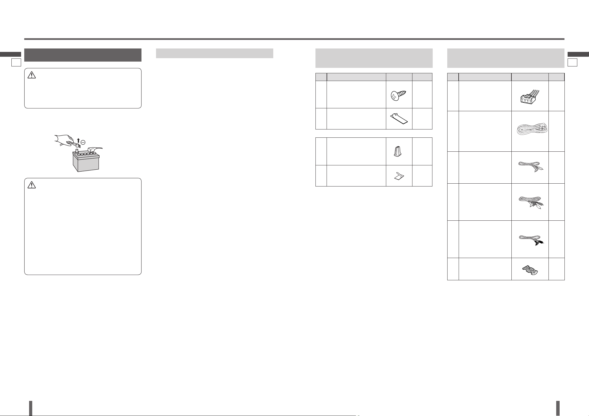
Disconnect the lead from the negative () battery
terminal before installation.
Wiring and installation with the negative () battery
terminal connected may cause electrical shock and
injury due to a short circuit.
Some cars equipped with the electrical safety
system have specifi c procedures of battery terminal
disconnection.
FAILURE TO FOLLOW THE PROCEDURE MAY
LEAD TO THE UNINTENDED ACTIVATION OF THE
ELECTRICAL SAFETY SYSTEM RESULTING IN
DAMAGE TO THE VEHICLE AND PERSONAL INJURY
OR DEATH.
Never use safety-related components for
installation, grounding, and other such functions.
Do not use safety-related vehicle components (fuel
tank, brake, suspension, steering wheel, pedals
airbags, etc.) for wiring or fi xing the product or its
accessories.
Installing the product on the air bag cover or in a
location where it interferes with airbag operation is
prohibited.
Check for piping, gasoline tank, electric wiring, and
other items before installing the product.
If you need to open a hole in the vehicle chassis to
attach or wire the product, fi rst check where the wire
harness, gasoline tank, and electric wiring are located.
Then open the hole from outside if possible.
Never have the power cord branched to supply other
equipment with power.
After installation and wiring, you should check the
normal operation of other electrical equipment.
The continuation of their using in abnormal conditions
may cause fi re, electrical shock or a traffi c accident.
In the case of installation to an airbag-equipped
car, confi rm warnings and cautions of the vehicle
manufacturer before installation.
Make sure the leads do not interfere with driving or
getting in and out of the vehicle.
Insulate all exposed wired to prevent short
circuiting.
Never try to repair the unit by yourself because it is
dangerous to do so.
Warning
This unit cannot be operated alone.
This unit is designed for users to connect one or more system devices to Panasonic car audio/AV unit at the same
time. For more details about safety information, refer to the operating instructions for the connected devices.
4
English
CY-TUN153U
5
English
CY-TUN153U
Safety Information
(continued)
Observe the following cautions when using this
unit.
This unit is designed for use exclusively in
automobiles.
Do not operate the unit for a prolonged period with
the engine turned off.
Operating the audio system for a long period of time
with the engine turned off will drain the battery.
Do not expose the unit to direct sunlight or excessive
heat.
Otherwise these will raise the interior temperature
of the unit, and it may lead to smoke, fi re, or other
damage to the unit.
Do not use the product where it will be exposed to
water, moisture, or dust.
Exposure of the unit to water, moisture, or dust may
lead to smoke, fi re, or other damage to the unit. Make
especially sure that the unit does not get wet in car
washes or on rainy days.
Observe the following cautions when installing.
If your car is equipped with air bag and/or anti-theft
systems specifi c procedures may be required for
connection and disconnection of the battery to install
this product.
FAILURE TO FOLLOW THE PROCEDURE MAY RESULT
IN THE UNINTENDED DEPLOYMENT OF AIR BAGS
OR ACTIVATION OF THE ANTI-THEFT SYSTEM
RESULTING IN DAMAGE TO THE VEHICLE AND
PERSONAL INJURY.
Refer wiring and installation to qualifi ed service
personnel.
Installation of this unit requires special skills and
experience. For maximum safety, have it installed by
your dealer. Panasonic is not liable for any problems
resulting from your own installation of the unit.
Follow the instructions to install and wire the product.
Not following the instructions to properly install and
wire the product could cause an accident or fi re.
Take care not to damage the leads.
When wiring, take care not to damage the leads.
Prevent them from getting caught in the vehicle
chassis, screws, and moving parts such as seat rails.
Do not scratch, pull, bend or twist the leads. Do not run
them near heat sources or place heavy objects on them.
If leads must be run over sharp metal edges, protect
the leads by winding them with vinyl tape or similar
protection.
Caution
Use the designated parts and tools for installation.
Use the supplied or designated parts and appropriate
tools to install the product. The use of parts other than
those supplied or designated may result in internal
damage to the unit. Faulty installation may lead to an
accident, a malfunction or fi re.
Do not install the product where it is exposed to
strong vibrations or is unstable.
Avoid slanted or strongly curved surfaces for
installation. If the installation is not stable, the unit may
fall down while driving and this can lead to an accident
or injury.
Ware gloves for safety. Make sure that wiring is
completed before installation.
To prevent damage to the unit, do not connect the
power connector until the whole wiring is completed.
Never mount the unit in any of the following locations
to avoid damage due to overheating;
• Near the heater port.
• Places like the dashboard or rear deck, where it may
be exposed to direct sunlight.
Do not mount the unit near the door, where it could be
exposed to rain.
You run the risk of interfering with the mounting or
causing damage by drilling into the gas tank, a wiring
harness, or other component.
Note that if your car has a driving computer or a
navigation computer, disconnecting the cable from the
battery may clear the memory.
Fit a vinyl cap over unused connection terminals, to
prevent contact with metal parts etc.
Caution
Observe the following cautions when handling the
batteries for the remote control unit.
Proper Use of the Batteries
Use only specifi ed battery (CR2025).
Match the polarity of the battery with the () and ()
marks in the battery case.
Replace a dead battery as soon as possible.
Remove the battery from the remote control unit when
not using it for an extended period of time.
Insulate the battery (by placing them in a plastic bag
or covering them with vinyl tape) before disposal or
storage.
Do not disassemble, recharge, heat or short the battery.
Do not throw a battery into a fi re or water.
Follow local regulations when disposing of a battery.
Improper use of a battery may cause overheating, an
explosion or ignition, resulting in injury or a fi re.
In case of battery leakage
Thoroughly wipe the battery liquid off the battery case
and insert new battery.
If any part of your body or clothing comes into contact
with battery liquid, wash it with plenty of water.
If battery liquid comes into contact with your eyes,
wash them with plenty of water and get immediate
medical attention.
Observe the following cautions when mounting the
TV antennas.
Attach the TV antenna so that it does not protrude.
If the antenna element extends beyond the front and
rear of the vehicle or car, it could hit eyes or heads of
pedestrians and potentially cause an accident or an
injury.
Place the TV antenna so that it does not impede driving
or visibility. If the antenna is in a position that impairs
forward or backward visibility, it could interfere with
driving and cause an accident.
Do not disassemble or modify the TV antenna. Such
modifi cation could start smoke or fi re.
Fasten the TV antenna securely, so that it cannot drop
off. If the screws are loose or the bond at the mounting
is weak, the antenna could fall off, potentially causing
damage to the car bodywork, accident or injury. Inspect
it occasionally.
Be sure to install the TV antenna on the inner side of
the rear window.
Be sure to connect the power lead of the TV antenna to
ACC power DC 12 V.
Keep the antenna away from the external amplifi er and
the rear speaker cord as much as possible.
Be sure to connect the grounding plate into the TV
antenna body. Otherwise, desensitization will occur.
Avoid contacting the back of the TV antenna body on
the adhesive surface.
Do not re-adhere the back of the TV antenna body to
avoid weakening adherability.
Avoid adhering the TV antenna on the heating wire as
much as possible.
Caution
3 4
6
English
CY-TUN153U
7
CY-TUN153U
Safety Information
(continued)
Contents
5 6
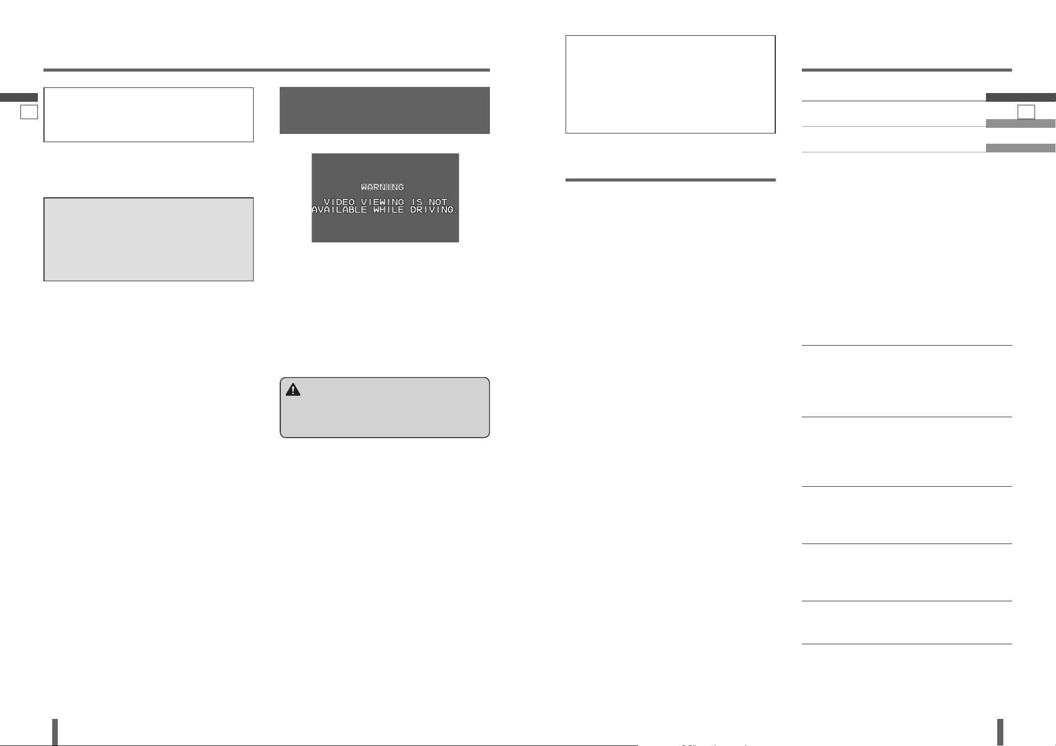
This system is designated so that you
cannot see TV or motion pictures while
you are driving.
Park your car in a safe and pull the parking brake (side
brake) lever before watching the monitor.
If a rear monitor (option) is connected to this unit, you
can continually see the rear monitor image even if the
parking brake (side brake) has not been pulled on.
Connection of Parking (Side)
Brake Connecting Lead
Part 15 of the FCC Rules
FCC Warning:
Any unauthorized changes or modifi cations to this
equipment would void the user’s authority to operate
this device.
The following applies only in the U.S.A.
Please follow the laws and regulations
of your province or country for
installation of the unit.
Features
Panasonic welcomes you to our constantly growing
family of electronic products owners.
We endeavor to give you the advantages of precise
electronic and mechanical engineering, manufactured with
carefully selected components, and assembled by people
who are proud of the reputation their work has built for
our company. We know this product will bring you many
hours of enjoyments, and after you discover the quality,
value and reliability we have built into it, you too will be
proud to be a member of our family.
This unit cannot be operated alone.
This unit is designed for users to connect
one or more system devices to Panasonic
car audio/AV unit at the same time.
Head Unit (option):
CQ-VD7003U, CQ-VD6503U, etc.
Can be combines with Panasonic
Expansion Module (CY-EM100U, option)
and other optional devices.
Receiving NTSC video system only
4ch Diversity TV Antenna system
12 Preset channels for each bands
Favorite channels can be written after you have set the
preset channel once.
Channels can also be deleted from the presets when no
longer required.
Note:
Market conditions regarding optional devices vary with
countries and regions. For further information, consult
your dealer.
Warning
When you connect external devices (option), be sure
to connect the parking brake (side brake) connection
lead. (page 23)
This unit is not compatible with digital
television broadcasts. (page 34)
For more information on digital
television broadcasts, refer to
publications from national governments
and television stations.
Note:
Only English is displayed on the OSD screen.
English 2
Français 36
Español 70
Safety Information ..................... 2
Features ................................. 7
Customer Services Directory ......... 8
Limited Warranty ...................... 9
Preparation ............................ 10
Components ........................... 11
Diversity TV Antenna ................. 12
DIVER (Diversity) Antenna Setting
Recommended System
and Operation ...................... 13
Names of Controls and Terminals .. 16
DIVER Setting ......................... 17
Basic TV Operation ................... 18
Channel Preset ........................ 19
Installation ............................. 20
Electrical Connections ............... 26
Troubleshooting ....................... 32
Tuner for Analog TV only ............ 34
Specifi cations ......................... 35
8
English
CY-TUN153U
9
English
CY-TUN153U
CANADA
WARRANTY SERVICE
FOR PRODUCT OPERATION ASSISTANCE, please contact:
Our Customer Care Centre:
Telephone #: (905) 624-5505
1-800 #: 1-800-561-5505
Fax #: (905) 238-2360
Email link: “Contact Us” on www.panasonic.ca
FOR PRODUCT REPAIRS, please locate your nearest
Authorized Servicentre at www.panasonic.ca:
Link : “Servicentres™ locator” under “Customer support”
Panasonic Factory Service:
Vancouver
Panasonic Canada Inc.
12111 Riverside Way
Richmond, BC V6W 1K8
Tel: (604) 278-4211
Fax: (604) 278-5627
IF YOU SHIP THE PRODUCT TO A SERVICENTRE
Carefully pack and send prepaid, adequately insured and
preferably in the original carton.
Include details of the defect claimed, and proof of date of
original purchase.
Customer Services Directory
U.S.A.
Obtain Product Information and Operating Assistance;
locate your nearest Dealer or Servicenter; purchase
Parts and Accessories; or make Customer Service and
Literature requests by visiting our Web Site at:
http://www.panasonic.com/support
or, contact us via the web at:
http://www.panasonic.com/contactinfo
You may also contact us directly at:
1-800-211-PANA (7262),
Monday-Friday 9 am-9 pm;
Saturday-Sunday 10 am-7 pm, EST.
Limited Warranty
ALL EXPRESS AND IMPLIED WARRANTIES, INCLUDING THE WARRANTY
OF MERCHANTABILITY, ARE LIMITED TO THE PERIOD OF THE LIMITED
WARRANTY.
Some states do not allow the exclusion or limitation of incidental or
consequential damages, or limitations on how long an implied warranty
lasts, so the exclusions may not apply to you.
This warranty gives you specifi c legal rights and you may also have
other rights which vary from state to state. If a problem with this product
develops during or after the warranty period, you may contact your dealer
or Servicenter. If the problem is not handled to your satisfaction, then
write to the warrantor’s Consumer Affairs Department at the addresses of
the warrantor.
PARTS AND SERVICE WHICH ARE NOT COVERED BY THIS LIMITED
WARRANTY ARE YOUR RESPONSIBILITY.
Customer’s Record
Model
No.
Serial
No.
Dealer’s
No.
Code
No.
Dealer’s
Address
Date of
Purchase
CANADA
Panasonic Canada Inc.
5770 Ambler Drive, Mississauga Ontario L4W 2T3
PANASONIC PRODUCT LIMITED WARRANTY
Panasonic Canada Inc. warrants this product to be free from defects in
materials and workmanship and agrees to remedy any such defect for a
period as stated below from the date of original purchase.
CAR AUDIO PRODUCT – ONE (1) YEAR, PARTS AND LABOUR
(The labour to install or remove the product is not warranted)
LIMITATIONS AND EXCLUSIONS
This warranty does not apply to products purchased outside Canada or to
any product which has been improperly installed, subjected to usage for
which the product was not designed, misused or abused, damaged during
shipping, or which has been altered or repaired in any way that affects the
reliability or detracts from the performance, nor does it cover any product
which is used commercially. Dry cell batteries are also excluded from
coverage under this warranty.
This warranty is extended to the original end user purchaser only. A
purchase receipt or other proof of the original purchase date is required
before warranty service is performed.
THIS EXPRESS, LIMITED WARRANTY IS IN LIEU OF ALL OTHER
WARRANTIES, EXPRESS OR IMPLIED, INCLUDING ANY IMPLIED
WARRANTIES OF MERCHANTABILITY AND FITNESS FOR A PARTICULAR
PURPOSE.
IN NO EVENT WILL PANASONIC CANADA INC. BE LIABLE FOR ANY
SPECIAL, INDIRECT OR CONSEQUENTIAL DAMAGES.
In certain instances, some jurisdictions do not allow the exclusion or
limitation of incidental or consequential damages, or the exclusion of
implied warranties, so the above limitations and exclusions may not be
applicable.
U.S.A.
PANASONIC CONSUMER ELECTRONICS COMPANY,
DIVISION OF PANASONIC CORPORATION OF AMERICA
One Panasonic Way, Secaucus, New Jersey 07094
PANASONIC SALES COMPANY,
DIVISION OF PANASONIC PUERTO RICO, INC.
Ave. 65 de infanteria, Km. 9.5, San Gabriel Industrial Park
Carolina, Puerto Rico 00985
PANASONIC AUTO PRODUCTS LIMITED WARRANTY
LIMITED WARRANTY COVERAGE
If your product does not work properly because of a defects in materials
and workmanship.
Panasonic Consumer Electronics Company or Panasonic Sales Company
(collectively referred to as “the warrantor”) will, for the length of the
period indicated in the chart below, which starts with the date of original
purchase (“warranty period”), at its option either (a) repair your product
with new or refurbished parts, or (b) replace it with a new or refurbished
product. The decision to repair or replace will be made by the warrantor.
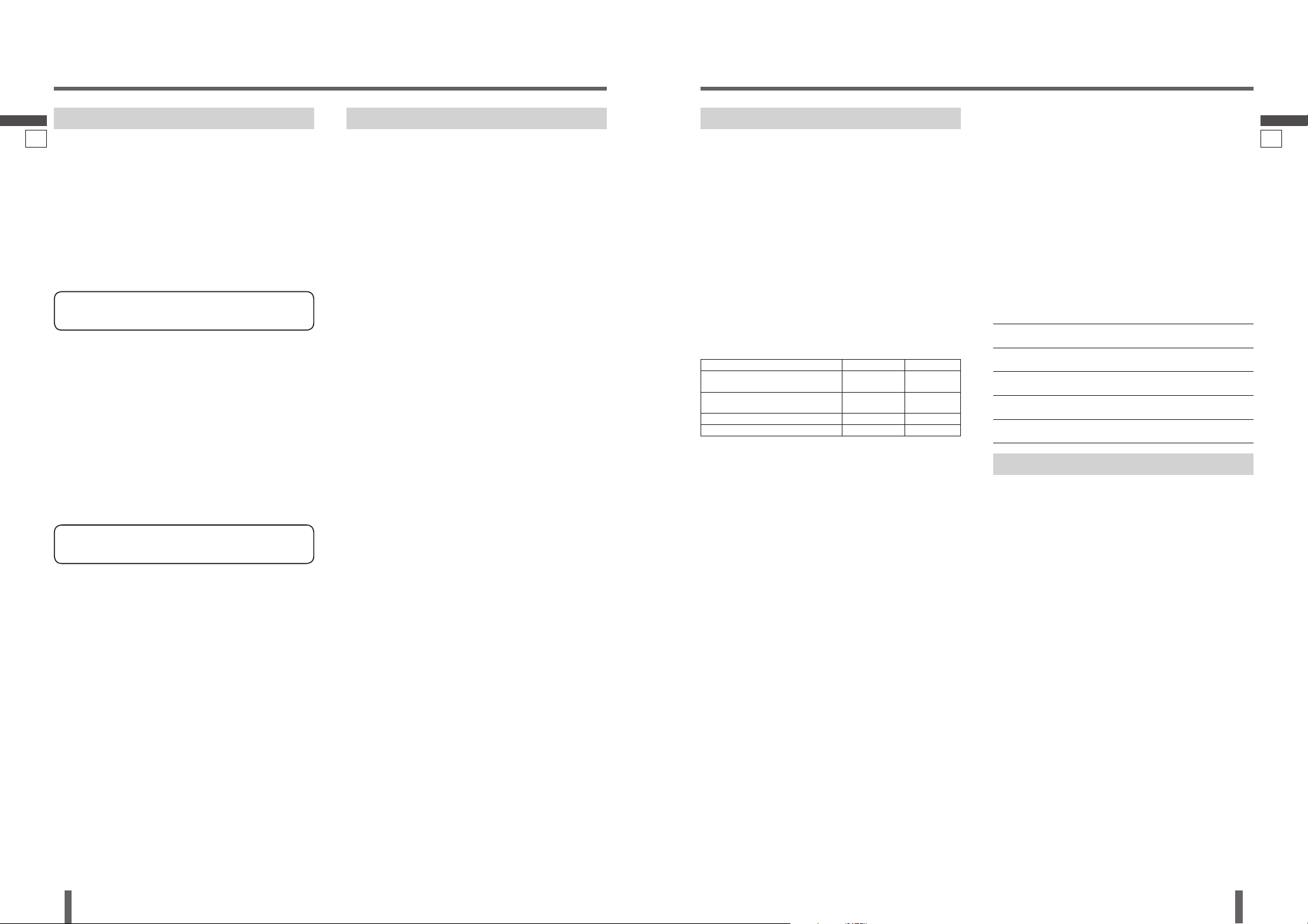
Categories Parts Labor
Audio Components (except items listed
below)
One (1) Year One (1) Year
MXE Series Audio Components (except items
listed below)
Two (2) Years Two (2) Years
Speakers One (1) Year Not Applicable
Accessories (in exchange for defective items) Ninety (90) Days Not Applicable
During the “Labor” warranty period, there will be no charge for labor.
During the “Parts” warranty period, there will be no charge for parts.
You must carry in or mail in your product during the warranty period.
If non-rechargeable batteries are included, they are not warranted. This
warranty only applies to products purchased and serviced in the United
States or Puerto Rico. This warranty is extended only to the original
purchaser of a new product which was not sold “as is”. A purchase receipt
or other proof of the original purchase date is required for warranty
service.
CARRY-IN OR MAIL-IN SERVICE
For Carry-In or Mail-In Service in the United States, call 1-800-211-PANA
(7262) or visit
Panasonic Web Site: http://www.panasonic.com
For assistance in Puerto Rico, call Panasonic Sales Company
(787)-750-4300 or fax (787)-768-2910.
LIMITED WARRANTY LIMITS AND EXCLUSIONS
This warranty ONLY COVERS failures due to defects in materials and
workmanship, and DOES NOT COVER normal wear and tear or cosmetic
damage. The warranty ALSO DOES NOT COVER damages which occurred
during shipment, failures which are caused by products not supplied
by the warrantor, failures which result from accident, misuse, abuse,
neglect, mishandling, misapplication, alteration, faulty installation, set-up
adjustment, maladjustment of consumer control, improper maintenance,
improper antenna, inadequate signal reception or pickup, power line
surge, improper voltage supply, lightning, modifi cation, commercial use
(such as use in hotels, offi ces, restaurants, or other business uses) or
rental use of the product, or service by anyone other than the technician
form Factory Servicenter or other authorized service centers, or damage
that is attributable to acts of God.
THERE ARE NO EXPRESS WARRANTIES EXCEPT AS LISTED UNDER
“LIMITED WARRANTY COVERAGE”. THE WARRANTOR IS NOT LIABLE
FOR INCIDENTAL OR CONSEQUENTIAL DAMAGES RESULTING FROM
THE USE OF THIS PRODUCT, OR ARISING OUT OF ANY BREACH OF
THIS WARRANTY. (As examples, this excludes damages for lost time,
cost of having someone remove or re-install an installed unit if applicable,
travel to and from the sevicer, and loss of media, date or other memory
contents. The items listed are not exclusive, but are for illustration only.)
For hearing or speech impaired TTY users,
TTY: 1-877-833-8855
Accessory Purchases:
Purchase Parts, Accessories and Instruction Books online
for all Panasonic Products by visiting our Web Site at:
http://www.pasc.panasonic.com
or, send your request by E-mail to:
npcparts@panasonic.com
You may also contact us directry at:
1-800-332-5368 (Phone) 1-800-237-9080 (Fax Only)
(Monday-Friday 9 am to 8 pm, EST.)
Panasonic Services Company
20421 84th Avenue South, Kent, WA 98032
(We accept Visa, MasterCard, Discover Card, American
Express, and Personal Checks)
For hearing or speech impaired TTY users,
TTY: 1-886-605-1277
Service in Puerto Rico
Panasonic Puerto Rico, Inc.
Panasonic Sales Company
Factory Servicenter:
Ave. 65 de infantería, Km. 9.5, San Gabriel Industrial Park,
Carolina, Puerto Rico 00985
Phone (787) 750-4300, Fax (787) 768-2910
Toronto
Panasonic Canada Inc.
5770 Ambler Drive
Mississauga, ON L4W 2T3
Tel: (905) 624-8447
Fax: (905) 238-2418
7 8

10
English
CY-TUN153U
11
English
CY-TUN153U
Preparation
Before settings:
Install and connect the Head Unit, optional devices and
this unit. (page 2031)
Mount the TV antenna. (page 24, 26)
Turn the power on.
Set the DIVER (Diversity) Antenna to “ON”.
Confi rm the electrical connection and video signal of
the connected devices.
DIVER (Diversity) Antenna Setting
(page 12)
Diversity TV Antenna:
Of the two antennae connected to the system, the one
with the best reception is automatically selected for TV
reception. Turning DIVER (Diversity) setting to “ON”
reduces noise.
Confi rm “ON” to receive a good reception.
Preparation Before Initial Use
Battery Replacement
Remove the battery holder with the remote control unit
placed on a fl at surface.
Stick your thumbnail into the groove, and push
the holder in the direction of the arrow at the same
time.
Put a battery in the case with () side facing up.
Put the case back.
Settings
Pull the insulation fi lm out
from the backside of remote
control gently.
Pull it out in the direction
of the arrow using a
tough pointed object.
Tough pointed object
Back side
Note:
Battery Information:
Battery Type: Panasonic lithium battery (CR2025)
(Included in the remote control)
Battery Life: Approximately 6 months under normal use
(at room temperature)
Remote Control Unit
Components
Caution
Remove and dispose of an old battery immediately.
Do not disassemble, heat or short a battery. Do not
throw a battery into a fi re or water.
Follow local regulations when disposing of a battery.
Improper use of a battery may cause overheating,
an explosion or ignition, resulting in injury or a fi re.
Warning
Keep a battery away from children to avoid the
risk of accidents. If an infant ingests a battery,
please seek immediate medical attention.
Note:
The number in parenthesis underneath each accessory
part name is the part number for maintenance and
service.
Accessories and their parts numbers are subject to
modifi cation without prior notice due to improvements.
Item Diagram Qty.
TV Tuner
1
TV Antenna
(YEAA12692A (L)/
YEAA12693A (R))
(L/R): from the inner side of
the car.
1 set
Remote Control Unit
(EUR7641040)
1
Lithium Battery for Remote
Control Unit
(Included in the remote
control)
<CR2025/1F>
1
Operating Instructions
(YFM284C547ZA)
1
Owners Information Card
1
Installation Hardware (screws, cords, etc.) (page 21)
9 10
12
English
CY-TUN153U
13
English
CY-TUN153U
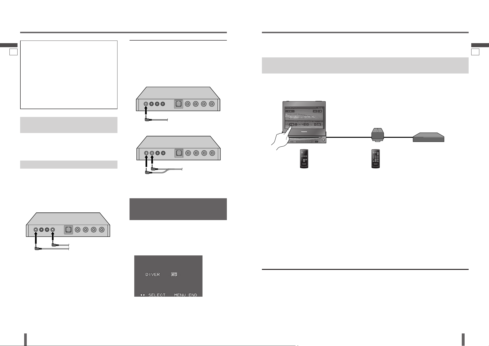
Recommended System and Operation
11 12
Diversity TV Antenna
To use the two TV antennae
provided
Plug the four terminals for the two antennae into the
tuner. Combine the tuner TV terminals and the antenna
terminals as shown on page 26.
Make sure the DIVER (Diversity) setting is “ON”.
To use the two optional antennae
Two antennae must be prepared.
Plug the four terminals for the two antennae into the
tuner. Combine the tuner TV terminals and the antenna
terminals as shown on page 26.
How to plug the antennae in when there is only one
antenna terminal.
Diversity TV Antenna:
Of the two antennae connected to the system, the one
with the best reception is automatically selected for TV
reception. Turning DIVER (Diversity) setting to “ON”
reduces noise.
To make effective use of this diversity function:
Connect both two TV antennae provided.
Turn DIVER (Diversity) setting to “ON”.
Note:
If only one is connected, the diversity function has
no effect.
Note:
If there is no alternative but to use only one optional TV
antenna, the diversity function has no effect.
1. The way to plug the antennae varies with the number
of antenna terminals.
How to plug the antennae in when there is only one
antenna terminal.
How to plug the antennae in when there are two
terminals.
Make sure the DIVER (Diversity) setting is “ON”.
2. Make sure the DIVER (Diversity) setting is “OFF”.
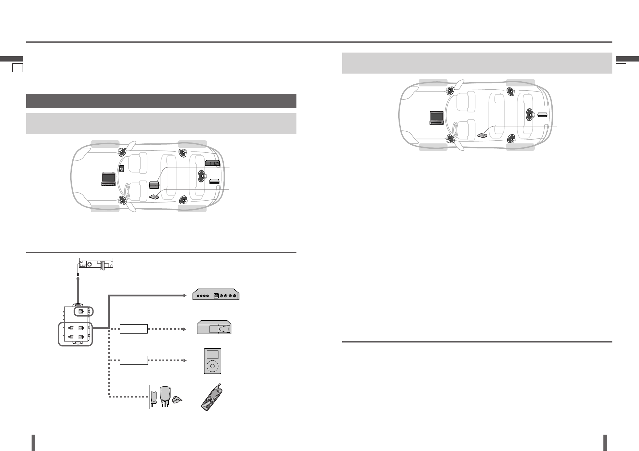
Expansion Module Connection
(Connection is possible even without an Expansion
Module Connection.)
TV tuner
We recommend using this TV tuner with the Panasonic Head Unit below.
For details on the head unit and head unit remote control operations, refer to the operating instructions for the Head Unit.
Head Unit with Touch Panel Control (CQ-VD7003U, CQ-VD6503U),
Expansion Module (CY-EM100U) and TV Tuner
Use the Head Unit touch panel to operate the TV tuner.
For details on the touch panel and remote control operations, refer to the chapter on TV operations in the operating
instructions for the Head Unit.
TV tuner remote control unit:
Use this remote control unit
for TV tuner setup operations
(DIVER (Diversity) Antenna
Setting).
Head Unit remote control unit:
This remote control unit enables you to
adjust the volume, switch sources, change
TV channels, and confi gure the auto preset
memory setting.
Combination of this TV tuner with the non-Panasonic
Head Unit (in-car audio system with a monitor/AV unit):
It will not be possible to operate this TV tuner with a
remote control unit, or that of the non-Panasonic Head
Unit.
For connection confi gurations other than the
recommended connection confi gurations above, refer to
the following pages.
Head Unit (CQ-VD7001U): Page 30
Rear Monitor (CY-VHD9401U): Page 31
The remote control units supplied with the Head Unit and
Rear Monitor cannot be used for TV tuner operations.
(Except for adjusting the volume, switching sources, etc.)
DIVER (Diversity)
Antenna Setting
Confi rm “ON” to receive a good reception.
Default: ON
Setting: ON/OFF
Press [PWR] (Power).
Press [MENU].
Press [] or [] to select “ON” or “OFF”.
Press [ENT] (ENTER) or [MENU] to set and return to
the previous display.
14
English
CY-TUN153U
15
English
CY-TUN153U
Recommended System and Operation
Head Unit
(In-dash color LCD monitor/DVD
player):
CQ-VD7003U, option
or
CQ-VD6503U, option
TV Tuner:
CY-TUN153U
Expansion Module:
CY-EM100U, option
This unit cannot be operated alone.
This unit is designed for users to connect one or more system devices to Panasonic car
audio/AV unit at the same time. For more details, refer to the operating instructions for
the connected devices.
System Connection Example
Head Unit with Touch Panel Control (CQ-VD7003U, CQ-VD6503U),
Expansion Module (CY-EM100U) and TV Tuner
Note:
Connect this unit to the Expansion Module (CY-
EM100U, option) with the Head Unit/Expansion Module
Connecting Cable and RCA cord (video) (supplied).
(page 27)
Head Unit with Touch Panel Control (CQ-VD7003U, CQ-VD6503U) and TV
Tuner
Head Unit
(In-dash color LCD
monitor/DVD player):
CQ-VD7003U, option
or
CQ-VD6503U, option
TV Tuner:
CY-TUN153U
Note:
Connect this unit to the Head Unit (CQ-VD7003U,
CQ-VD6503U, option) with the Head Unit/Expansion
Module Connecting Cable and RCA cord (video)
(supplied). (page 28, 29)
13 14
Head Unit:
CQ-VD7003U (option)
Expansion Module:
CY-EM100U (option)
TV Tuner:
CY-TUN153U
Up to 4 units
Conversion Cable for DVD/CD
Changer is required
(CA-CC30U, option)
CD Changer
(CX-DP880, option)
iPod
®
Direct Cable is required
(CA-DC300U, option)
Hands-Free Kit featuring
Bluetooth
®
technology
(CY-BT100U, option)
iPod
Cellular Phone
System-up Connector
(continued)
Bluetooth®
The Bluetooth word mark and logo are owned by the
Bluetooth SIG, Inc and any use of such marks by
Matsushita Electric Industrial Co.,Ltd. is under license.
Other trademarks and trade name are those of their
respective owners.
iPod
®
iPod is a trademarks of Apple Computer, Inc., registered
in the U.S. and other countries.
16
English
CY-TUN153U
17
English
CY-TUN153U
15 16
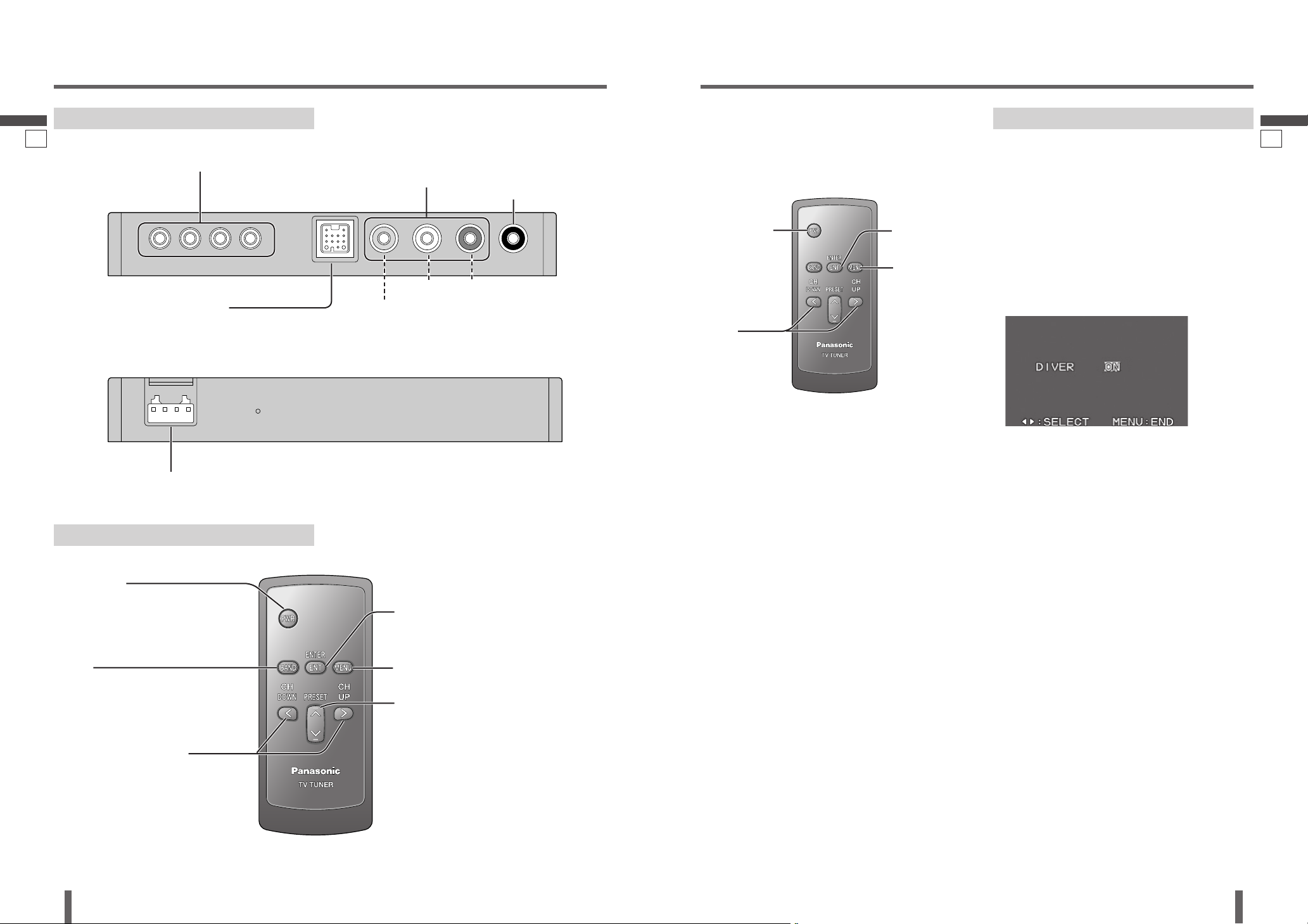
Names of Controls and Terminals
TV Tuner Unit
DIVER Setting
Remote Control Unit
REMOTE IN (Black)
Terminal for connecting a
Head Unit’s remote output
terminal.
TV OUT
Terminal for connecting a Rear
Monitor (CY-VHD9401U, etc.,
option).
TO HEAD UNIT/EXPANSION MODULE
(System-up Connector)
Terminal for connecting a Head Unit (CQ-VD7003U, CQVD6503U, option)/Expansion Module (CY-EM100U,
option).
TV ANT IN
Terminal for connecting TV antennas (supplied)
POWER SUPPLY
Terminal for connecting to the power connector
[PWR] (Power)
Switches on/off the power. (page 18)
[BAND]
Selects TV band. (page 18)
Searches for channels and memorizes
them automatically. (page 19)
[ENT] (ENTER)
Determines an operation or item. (page 17)
Shows TV channel display. (page 18)
[MENU]
Shows the menu screen. (page 17)
[] [] (PRESET)
Selects the preset channel. (page 19)
Sets the preset channel writing/deleting
mode. (page 19)
[] (CH DOWN) [] (CH UP)
Selects an operation or item. (page 17)
Selects or searches the channel. (page
18)
DIVER (Diversity) Antenna Setting
Diversity TV Antenna:
Of the two antennae connected to the system, the one
with the best reception is automatically selected for TV
reception. Turning DIVER (Diversity) setting to “ON”
reduces noise.
Confi rm “ON” to receive a good reception.
Default: ON
Setting: ON/OFF
Press [PWR] (Power).
Press [MENU].
Press [] or [] to select “ON” or “OFF”.
Press [ENT] (ENTER) or [MENU] to set and return to
the previous display.
Note:
Only English is displayed on the OSD screen.
[ENT] (ENTER)
[PWR] (Power)
[MENU]
[] []
VIDEO (Yellow)
Connect RCA cord to the video input terminal of the
Head Unit when connecting Head Unit/Expansion Module
Connecting Cable to the Head Unit.
L (White) R (Red)
Refer to page 12 about the DIVER (Diversity) Antenna
setting.
Read the explanation on this page as required.
Note:
Point the emitter of the remote controller at the Head
Unit or the monitor.
18
English
CY-TUN153U
19
English
CY-TUN153U
17 18
Power
Turn your car’s ignition key to the ACC or ON position.
ON: Press [PWR] (Power).
OFF: Press [PWR] (Power) again.
Note:
When changing the source to TV tuner on Head Unit
(CQ-VD7003U, CQ-VD6503U, option), the power is
turned on automatically.
Band Selection
Press [BAND].
TV1 TV2
Note:
TV2 is provided to allow more preset channels in
memory.
Channel Selection
Press [] (CH DOWN) or [] (CH UP).
[] (CH UP): Higher channel number
[] (CH DOWN): Lower channel number
Press and hold [] (CH DOWN) or [] (CH UP) for more
than 0.5 seconds, then release it. Seeking will start.
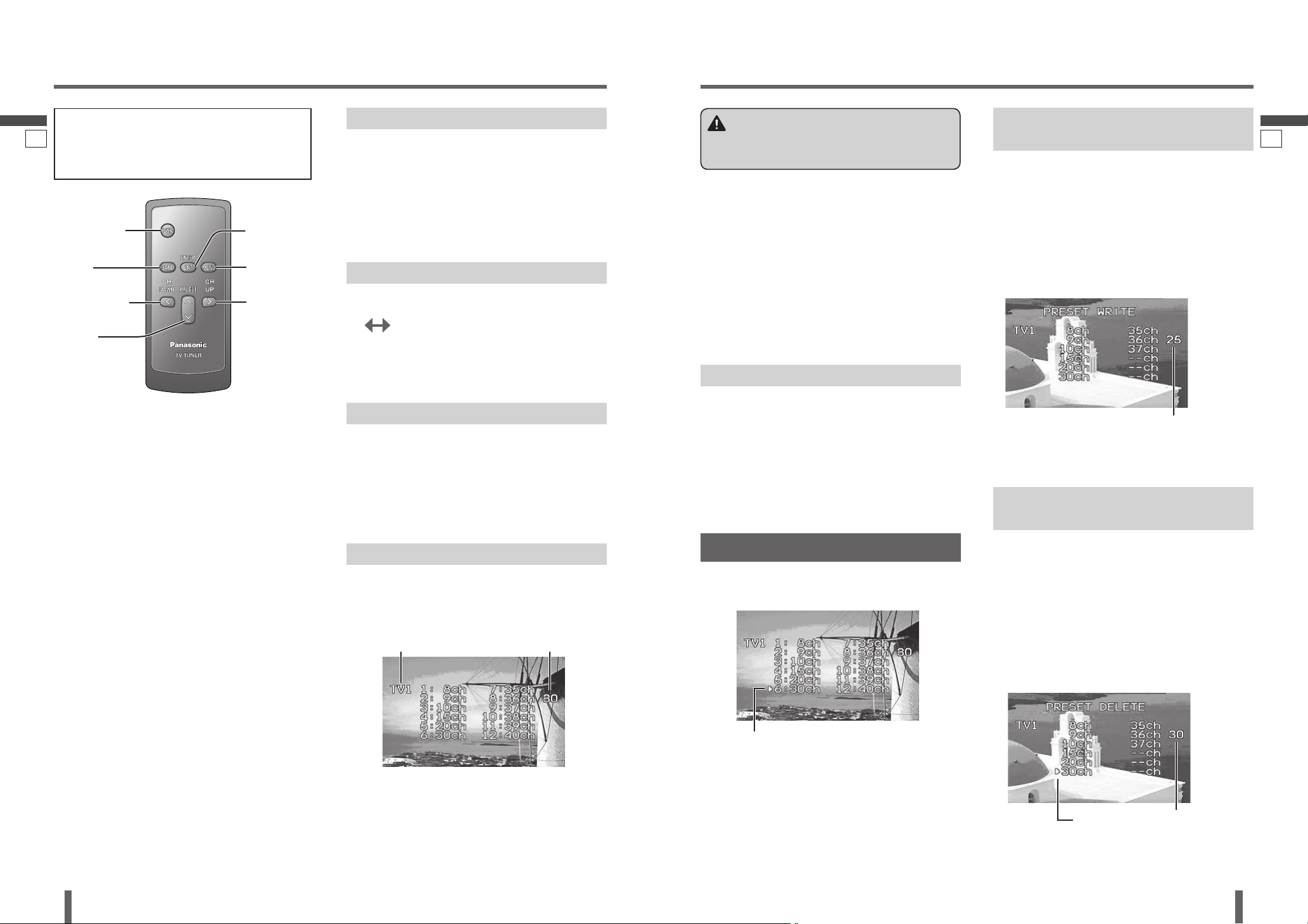
TV Channel Display
Press [ENT] (ENTER).
Press [ENT] (ENTER) again to display off.
Example: When preset channel is not set.
Basic TV Operation
Up to 12 channels can be stored in each of the TV1 and
TV2 band selections.
TV2 is provided to allow more preset channels in
memory. Channels that could not be placed in memory
on the Band TV1 can be placed on the Band TV2.
If Band TV1 is suffi cient to hold all desired channels,
they should usually be preset to that band.
Note:
New channels overwrite existing saved stations after
these procedures.
Auto Preset Channel Memory
With this operation, channels with good receiving
conditions can be automatically stored in the preset
memory.
Press [BAND] to select the TV band.
Press and hold [BAND] for more than 2 seconds.
12 channels with fi rst to 12th highest in signal
strength will be preset to each band. (They are listed in
order, from the earliest channel number.)
Preset Channel Calling
Press [BAND] to select the TV band.
Press [] or [] (PRESET).
Warning
To ensure safety, never attempt to preset channels
while you are driving.
Note:
Only English is displayed on the OSD screen.
Background of the display becomes blue when the unit
cannot get a good reception on the TV.
[ENT] (ENTER)
[PWR] (Power)
[BAND]
[] (CH DOWN)
[] (CH UP)
TV band Selected TV channel number
Selected preset channel number
Channel Preset
[] []
(PRESET)
[MENU]
Writing Preset Channel (PRESET
WRITE)
Favorite channels can be written after you have set the
preset channel once.
Example:
The 25 channel is written in the TV1 preset channel list.
Press and hold [] (PRESET) for more than 2
seconds.
Preset channel writing mode display appears.
Press [] (CH DOWN) or [] (CH UP) to select
channel you want to write.
Press [ENT] (ENTER) or [BAND] to set.
Press [MENU] to exit the preset channel writing mode.
Deleting Preset Channel (PRESET
DELETE)
Channels can also be deleted from the presets when no
longer required.
Example:
The 30 channel is deleted in the TV1 preset channel list.
Press and hold [] (PRESET) for more than 2
seconds.
Preset channel deleting mode display appears and
preset 1 channel is received.
Press [] or [] (PRESET) to select preset channel
you want to delete.
TV channel you want to write
Press [ENT] (ENTER) or [BAND] to set.
Press [MENU] to exit the preset channel deleting
mode.
Preset channel you want to delete
Refer to the CQ-VD7003U and CQ-VD6503U
instruction manuals for information on TV operation
on the CQ-VD7003U and CQ-VD6503U touch panel
and remote control.
20
English
CY-TUN153U
21
English
CY-TUN153U
No. Item Diagram Qty.
Power Connector
(YEAJ012884)
1
Head Unit/Expansion
Module Connecting
Cable
(3 m)
(YEAJ071812)
(for Expansion Module)
1
RCA Cord (3 m)
(YEAJ071819)
(for video connector)
1
RCA Cord (3 m)
(YEAJ071820)
(for audio connector)
1
RCA Cord (3 m)
(YEAJ071821)
(for remote control
connector)
1
Clip Connector
(YEAT034C012)
1
Installation
Installation Precautions
This unit should be installed by a professional installer.
In case of diffi culty, please consult your nearest
authorized Panasonic Servicenter.
This system is to be used only in a 12 V DC battery
system (car) with negative ground.
Follow the electrical connections carefully (page 26).
Failure to do so may result in damage to the unit.
Connect the power lead after all other connections are
made.
Be sure to connect the battery lead (yellow) to the
positive terminal () of the battery or fuse block (BAT)
terminal.
Insulate all exposed wires to prevent short circuiting.
Secure all loose wires after installing the unit.
Please carefully read the operating instructions of the
respective equipment before connecting it to this unit.
Installation Hardware
(For Installation)
No. Item Diagram Qty.
Tapping Screw
(516 mm)
(XTT516AFZ)
4
Velcro Tape
(YFX994C135ZA)
2
Installation Hardware
(For Wiring)
Note:
The number in parenthesis underneath each accessory
part name is the part number for maintenance and
service.
Accessories and their parts numbers are subject to
modifi cation without prior notice due to improvements.
Use the supplied screws for installation exclusively. In
case of losing any of them, please order the specifi c
screw.
19 20
Preparation
Caution
Please follow the laws and regulations of your
province or country for installation of the unit.
We strongly recommended you to wear gloves for
installation work to protect yourself from injuries.
Disconnect the cable from the negative () battery
terminal (see caution below).
Caution
If your car is equipped with air bag and/or anti-
theft systems specifi c procedures may be required
for connection and disconnection of the battery to
install this product.
Before attempting installation of this electronic
component contact your car dealer or manufacturer
to determine the required procedure and strictly
follow their instructions.
FAILURE TO FOLLOW THE PROCEDURE MAY
RESULT IN THE UNINTENDED DEPLOYMENT OF
AIR BAGS OR ACTIVATION OF THE ANTI-THEFT
SYSTEM RESULTING IN DAMAGE TO THE VEHICLE
AND PERSONAL INJURY.
Antenna Clamp 4
Cord Clamp (for antenna) 4
(YEP9FZ3041)
22
English
CY-TUN153U
23
English
CY-TUN153U
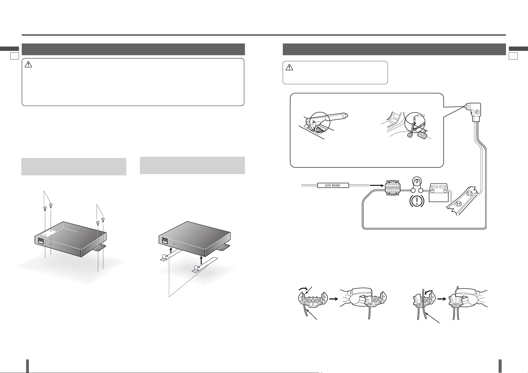
Mount the unit on the car carpet
by using Velcro tape .
Attach the seal side of the Velcro Tape to the unit, then
mount the unit on the carpet.
Unit Installation by using the Tapping
Screw . (Recommended)
Mounting the Tuner Unit
Caution
Never mount the unit in any of the following locations to avoid damage due to overheating;
• Near the heater port.
• Places like the dashboard or rear deck, where it may be exposed to direct sunlight.
Do not mount the unit near the door, where it could be exposed to rain.
You run the risk of interfering with the mounting or causing damage by drilling into the gas tank, a wiring harness, or
other component.
For mounting the unit on inclined surface, Velcro tape fi xation is too weak, and screw
fi xation is recommended.
Note:
Apply an anticorrosive to the holes and tapping screws.
Keep a safe distance between the unit and other electronic equipment.
Note:
Some carpet materials may not be suitable for this
mounting method. In this case, please contact your
nearest Panasonic Servicenter for installation.
Installation
(continued)
Connecting the Parking Brake (Side Brake) Connection Lead
The parking brake (side brake) switch position varies with the car
model. For details on the exact location of the parking brake (side brake)
switch in your car, contact your dealer.
Parking Brake (Side Brake) Connection
Lead
(Bright green)
When the parking brake (side brake) lever
is engaged, the unit is grounded by the
chassis.
Parking Brake (Side Brake)
Connection Lead
(Bright green)
Parking brake (side brake)
switch
Brake light
Battery
Car chassis
Come up to this point.
Power source side lead
Hand brake Foot brake
Attach a Clip Connector to the end of the parking
brake (side brake) connection lead.
The Clip Connector is connected to the power
source side lead of the parking brake (side brake)
lever.
Clip connector
Caution
For safety, be sure to ask your nearest professional
installer to do this connection.
21 22
Velcro Tape
Tapping Screw
Tapping Screw
24
English
CY-TUN153U
25
English
CY-TUN153U
Installation
(continued)
23 24
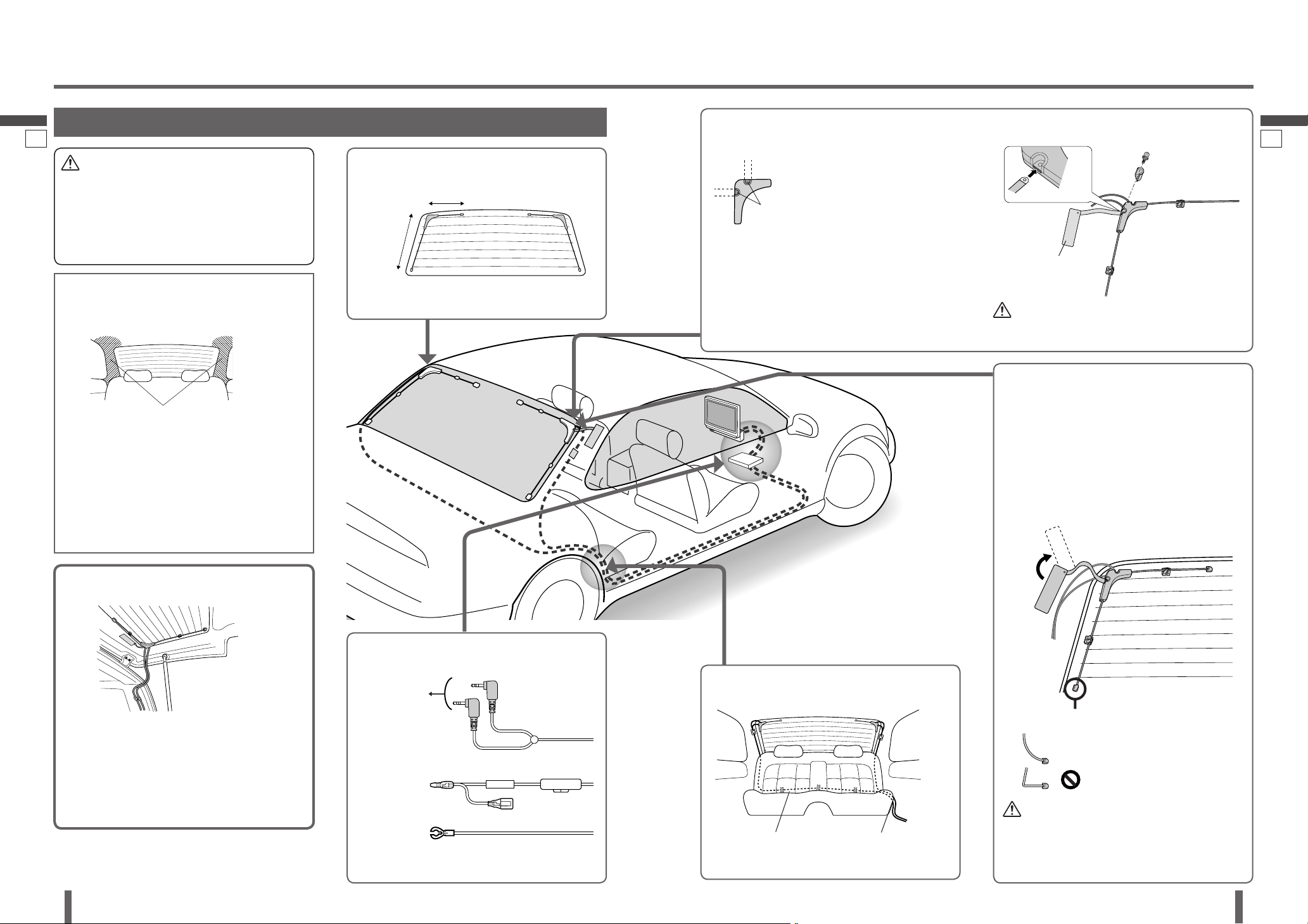
Mounting the TV Antenna
Caution
Be sure to install the TV antenna on the inner side of
the rear window.
Be sure to connect the power lead of the TV antenna
to ACC power DC 12 V.
Keep the antenna away from the external amplifi er
and the rear speaker cord as much as possible.
Route the cord behind
the rear seat and affi x it
with adhesive tape.
Preparations:
Remove the upholstery at both sides of the
rear window to establish a ground.
Observe the following to enhance adherability.
Wipe the inner surface of the rear window with a
wet and soft cloth along the heating wire. But do
not leave water droplets on the glass.
When the outside-air temperature is less than 20C
{68F}, switch on the rear window defogger or the
car heater to warm the surface of the rear window
for approx. 5 minutes.
For a hatchback type:
Stick the grounding plate skillfully and hold the loose
antenna element with the Antenna Clamp so that the
element will not become caught in the hatchback door.
Adjust the cord length so that the cord does not
interfere with the movement of the hatchback door,
and secure the cord with Cord Clamp .
Straighten the bent antenna element.
Confi rm the adhering positions.
Longer
side
To TV antenna
connector on
the unit.
Ground Lead
To a clean, bare metallic part
of the car chassis.
Select a suitable screw point for
the grounding plate to adhere
to a metal part and remove the
screw and the terminal cover.
Follow the steps below to install the grounding plate.
Insert the grounding plate into the antenna body.
Hold the grounding plate with the terminal cover.
Screw the grounding plate.
Hold the antenna element with the Antenna Clamp .
Caution
Be sure to connect the grounding plate. Otherwise,
desensitization will occur.
Follow the steps below to affi x the antenna securely.
Affi x the antenna body.
Straighten the antenna element and affi x it.
Put the Antenna Clamp on the center of the
antenna element.
Adjust the angle and position of the grounding plate
and affi x it.
For some models, you cannot straighten the
longer element.
Caution
Avoid contacting the adhesive surface.
Do not re-adhere to avoid weakening adherability.
Avoid adhering on the heating wire as much as
possible.
Some models restrict the installation of
the TV antenna due to rear window size
or open/close of the hatch. Contact your
dealer.
Cord routing
Hold the cord with a
Cord Clamp .
Remove the upholstery.
Affi x the antenna temporarily with adhesive tape after
confi rming the antenna position.
Shorter side
Antenna cable identifi cation
Antenna Cord
Power lead
To ACC power,
+12 V DC.
Insert the grounding plate into the antenna body and hold the antenna element with the Antenna
Clamp .
Screw points
Peel the sheet from the back of the
antenna body and affi x it. Then, affi x the
grounding plate on a metal part.
Adjust
Comfortably curving
No bending
0.5A
ACC 0.5A
(Fuse 0.5 A)
(Red)
(Black)
Insert
Screw
Terminal cover
Grounding Plate
Route the cord inside the
upholstery and under the
carpet.
(for each antenna)
To another’s
power lead
26
English
CY-TUN153U
27
English
CY-TUN153U
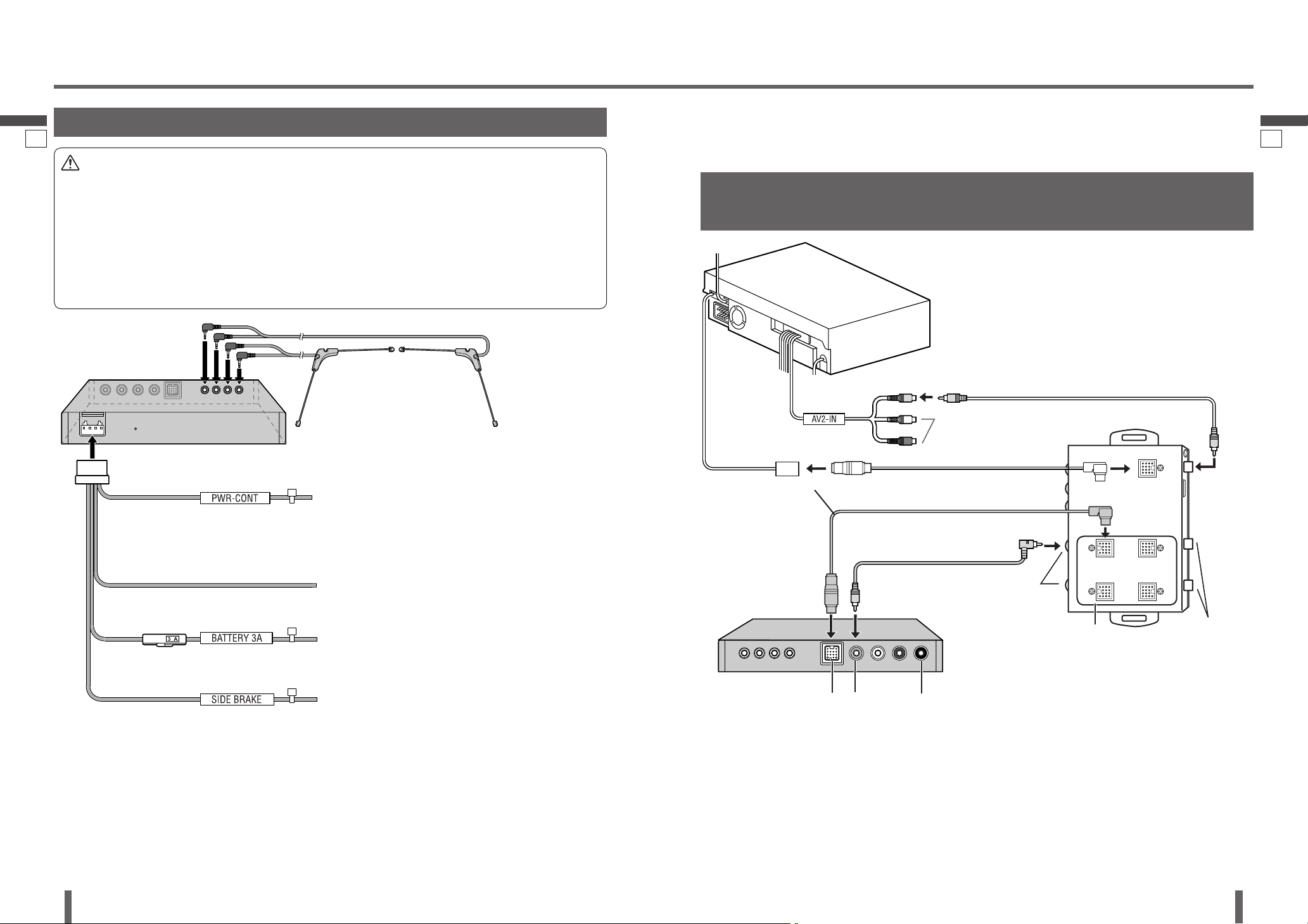
Electrical Connections
Wiring Diagram
25 26
Power Control Lead
(Blue/white stripe)
To the external amplifi er control power lead of the Head
Unit.
To ACC power, 12 V DC, if the Head Unit has no
external amplifi er control power lead.
Battery Lead
(Yellow)
To the car battery, continuous 12 V DC.
Ground Lead
(Black)
To a clean, bare metallic part of the car chassis.
Parking Brake (Side Brake) Connection Lead
(Bright green)
Be sure to wire the parking brake (side brake) for safety
and preventing accidents.
TV Tuner:
CY-TUN153U
Power connector
Caution
This unit is designed for use in a car having a 12 V negative ground battery system.
To prevent damage to the unit, be sure to follow the connection diagram.
Do not insert the power connector into the unit until the wiring is completed.
Be sure to insulate any exposed wires to prevent short circuiting with the car chassis. Bundle all cables, and prevent
cable terminals from touching any metal parts.
Note that if your car has a driving computer or a navigation computer, disconnecting the cable from the battery may
clear the memory.
Run the cords avoiding the spots where the temperature can be extremely high.
Fit a vinyl cap over unused connection terminals, to prevent contact with metal parts etc.
Note:
Strip about 5 mm of the lead ends for connection.
Be sure to fully plug in the connectors. Secure them
with clamps and tapes.
All other installation methods require the use of
dedicated metal fi ttings. Consult with a qualifi ed
servicing engineer or your dealer if other methods are
required.
Note:
Refer to individual instruction and installation manuals
for each device for detailed installation and wiring.
Connect this unit to the Expansion Module (CY-
EM100U, option) with the Head Unit/Expansion Module
Connecting Cable and RCA cord (video) (supplied).
When the device that provides video output is
connected to the System-up Connector, connect the
video cable to input connector below the port to which
the System-up Connector is connected.
Connecting with Head Unit (CQ-VD7003U) and Expansion
Module (CY-EM100U)
This unit cannot be operated alone.
This unit is designed for users to connect one or more system devices to Panasonic car
audio/AV unit at the same time.
Note for the Head Unit remote control unit (page 13):
With some Head Units, the Head Unit remote control
unit may not have buttons intended specifi cally for TV
operation, so some operations cannot be used for TV
operation. But that does not mean that the tuner or the
Head Unit are malfunctioning.
(Fuse 3 A)
TV Antenna
Refer to page 24 for the TV
antenna connection.
REMOTE IN
Not used.
Head Unit:
CQ-VD7003U
Expansion Module:
CY-EM100U
TV Tuner:
CY-TUN153U
VIDEO
(Yellow)
TO EXPANSION
MODULE
RCA cord
Head Unit/Expansion
Module Connecting Cable
To one of the system-up
connectors (input)
Head Unit/Expansion Module Connecting
Cable (supplied with CY-EM100U)
Port 1 IN to 4 IN
System-up connectors
(input)
Video input
Video input
RCA cord (option)
Video (Yellow)
Video
(Yellow)
If the Expansion Module (CY-EM100U, option) is not
connected and the ACC is not mounted on the vehicle:
Connect the power control lead of this unit to the
external amplifi er control power lead of the Head Unit.
If this connection is not made, the battery will run
down.
Not used.

28
English
CY-TUN153U
29
English
CY-TUN153U
27 28
Electrical Connections
(continued)
Connecting with Head Unit (CQ-VD7003U)
Note:
Refer to individual instruction and installation manuals
for each device for detailed installation and wiring.
Connect this unit to the Head Unit (CQ-VD7003U,
option) with the Head Unit/Expansion Module
Connecting Cable and RCA cord (video) (supplied).
Connecting with Head Unit (CQ-VD6503U)
Note for the Head Unit remote control unit (page 13):
With some Head Units, the Head Unit remote control
unit may not have buttons intended specifi cally for TV
operation, so some operations cannot be used for TV
operation. But that does not mean that the tuner or the
Head Unit are malfunctioning.
Note:
Refer to individual instruction and installation manuals
for each device for detailed installation and wiring.
Connect this unit to the Head Unit (CQ-VD6503U,
option) with the Head Unit/Expansion Module
Connecting Cable and RCA cord (video) (supplied).
Note for the Head Unit remote control unit (page 13):
With some Head Units, the Head Unit remote control
unit may not have buttons intended specifi cally for TV
operation, so some operations cannot be used for TV
operation. But that does not mean that the tuner or the
Head Unit are malfunctioning.
REMOTE IN
Not used.
Head Unit:
CQ-VD7003U
VIDEO
(Yellow)
TV Tuner:
CY-TUN153U
TO HEAD UNIT
RCA cord
Head Unit/Expansion Module Connecting Cable
Video (Yellow)
Video (Yellow)
REMOTE IN
Not used.
Head Unit:
CQ-VD6503U
VIDEO
(Yellow)
TV Tuner:
CY-TUN153U
TO HEAD UNIT
RCA cord
Head Unit/Expansion Module Connecting Cable
Video (Yellow)
Video (Yellow)
AV2-IN
Head Unit with System up Connector
Not used.
30
English
CY-TUN153U
31
English
CY-TUN153U
Electrical Connections
(continued)
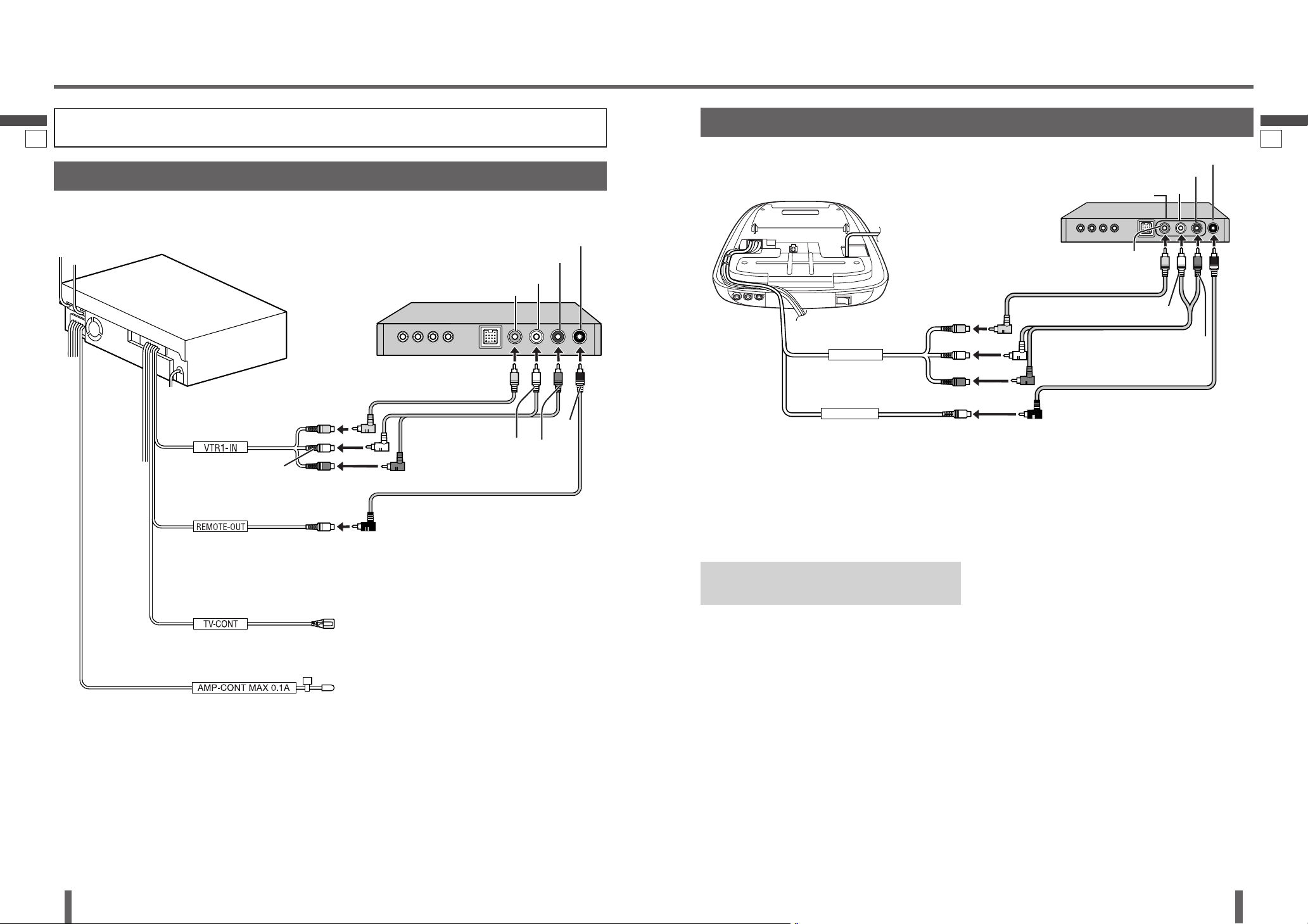
Connecting with Head Unit (CQ-VD7001U)
Note:
Refer to individual instruction and installation manuals
for each device for detailed installation and wiring.
Connect this unit to the Head Unit (CQ-VD7001U,
option) with RCA cord (video, audio, remote) (supplied).
29 30
Head Unit:
CQ-VD7001U
VIDEO (Yellow)
TV Tuner:
CY-TUN153U
RCA cord
If the ACC is not mounted on the vehicle:
Connect the power control lead of this unit to the
external amplifi er control power lead of the Head Unit.
If this connection is not made, the battery will run
down.
RCA cord
Video (Yellow)
RCA cord
L (White)
R (Red)
L (White)
R (Red)
REMOTE IN (Black)
R (Red)
L (White)
Video (Yellow)
(Black)
(Black)
TV-CONT
Not used.
Head Unit without System up Connector
Connecting with Rear Monitor
(CY-VHD9401U)
VTR1-IN
REMOTE-OUT
Rear Monitor:
CY-VHD9401U
TV OUT
REMOTE IN (Black)
R (Red)
L (White)
VIDEO (Yellow)
Video (Yellow)
(Black)
L (White)
R (Red)
(Black)
R (Red)
L (White)
Video (Yellow)
Note:
Refer to individual instruction and installation manuals
for each device for detailed installation and wiring.
Connect this unit to the Rear Monitor (CY-VHD9401U,
option) with RCA cord (video, audio, remote) (supplied).
When Connecting the Rear
Monitor (CY-V7001U, option)
Refer to individual instruction and installation manuals
for each device for detailed installation and wiring.
Connect this unit to the Rear Monitor (CY-V7001U,
option) with RCA cord (video, audio, remote) (supplied).
The rear monitor can be connected to this unit, but
audio is not emitted from the receiver (option).
RCA cord
RCA cord
RCA cord
TV Tuner:
CY-TUN153U
 Loading...